

Abstract
This article reviews an improved methodology and technology for crafting a multi-electrode spiral cuff for the selective activation of nerve fibres in particular superficial regions of a peripheral nerve. The analysis, structural and mechanical properties of the spot welds used for the interconnections between the stimulating electrodes and stainless-steel lead wires are presented. The cuff consisted of 33 platinum electrodes embedded within a self-curling 17-mm-long silicone spiral sheet with a nominal internal diameter of 2.5 mm. The weld was analyzed using scanning electron microscopy and nanohardness tests, while the interconnection was investigated using destructive load tests. The functionality of the cuff was tested in an isolated porcine vagus nerve. The results of the scanning electron microscopy show good alloying and none of the typical welding defects that occur between the wire and the platinum foil. The results of the destructive load tests show that the breaking loads were between 3.22 and 5 N. The results of the nanohardness testing show that the hardness of the weld was different for the particular sites on the weld sample. Finally, the results of the functional testing show that for different stimulation intensities both the compound action potential deflection and the shape are modulated.
Introduction
Many biomedical devices that interact with the peripheral nervous system have been developed for both recording and stimulation. Among a number of factors, the functionality of stimulating electrode systems, implanted onto peripheral nerves in humans, depend on the design, motion, mechanics, material composition and surface properties. All applications of chronically implanted neural prostheses require electrodes that are capable of providing a safe and reliable electrical stimulation that is dependent on the surface and bulk properties of the used materials. Material-modification techniques that optimize both the surface and bulk properties should be applied. Because the installation of such an electrode system for a peripheral nerve potentially causes mechanical injuries, it is necessary to consider and resolve all these issues.
Considerable scientific and technological efforts have been devoted to developing systems of electrodes that interface the human nervous system with implantable electronic devices. Recent work has also led to advances in cuffs that enable selective fibre-bundle functional electrical stimulation1. As a result, multi-electrode nerve cuffs have been used for the electrical stimulation of peripheral nerves for several decades2–4. Twenty years ago, Haugland5 presented a simple method for constructing nerve cuffs based on using platinum foil electrodes and silicone. In-vivo testing showed that in a 1-year period none of the cuffs failed. However, the cuffs were designed to have a small number of circular electrodes enabling only whole-nerve stimulation instead of numerous individual electrodes to stimulate selectively particular superficial compartments. The trend in neural prostheses that use selective nerve stimulation for therapy is towards single-part systems with a large number of stimulating electrodes, each of which selectively stimulates neural tissue or records a neural response.
Among the different multi-electrode designs, the self-sizing spiral design was chosen for the cuff, because of its ability to selectively stimulate superficial compartments of the nerve when wrapped around6–10. Spiral cuffs were used to re-establish the diminished function of internal organs and glands such as the heart, lungs, stomach, bladder and pancreas or to treat chronic diseases in humans by stimulation of the vagus nerve11–17. Advances in vagus-nerve stimulation have increased the need for cuff designs that can selectively modulate the function of the desired internal organ also via the selective stimulation of selected populations of nerve fibres. This selectivity has proved to be difficult to achieve9,18. As a result, most cuffs are manufactured using medical-grade silicone materials in combination with platinum foils that are connected to stainless-steel lead wires using different technologies.
Although cuffs are not entirely without disadvantages, the mechanical interface, and thus the reproducibility of selective stimulations, is still superior to alternative solutions. External pressures applied to the peripheral nerve can elicit blood flow occlusion that leads to nerve degeneration and demyelination. To ensure the highest possible biocompatibility and stability, when implementing a cuff for nerve stimulation, this tissue damage must be avoided. Therefore, the technology for crafting the spiral nerve cuffs should consider cuff-tissue interactions as well as the appropriate technological solution. Grill and Mortimer19 reported on the input-output properties of chronically implanted, silicone spiral cuffs, containing 12 platinum electrodes implanted on the sciatic nerves of cats. Their results suggested that tissue encapsulation actually stabilized the chronically implanted cuffs, while in more than half of the cuffs, the interconnections and/or lead wires were irreparably damaged. Racz and Heavner20 suggested that the use of the cuff for peripheral nerve stimulation has little future due to the fact that the cuff does not allow the stimulation of individual axons. However, advances in cuff design has enabled systems with a number of electrodes that are chronically interfaced to the peripheral autonomous nervous system6,21,22.
Among the different materials used to produce stimulating electrodes, platinum is commonly used in the form of a pure metal (99.93 wt %). The relatively low strength of pure platinum can be increased in multi-electrode stimulating systems by plastic deformation and partial annealing. To improve the mechanical properties of platinum, to analyse any failure and determine its microstructure, metallographic analysis with electrolytic etching can be used23,24. Apart from chemical inertness, platinum also has a number of physical properties of great value for use in implantable stimulating electrode technology. The structural properties of a cold-rolled platinum foil used to manufacture multi-electrode spiral nerve cuffs that can be additionally improved with thermal treatments were considered in the study25,26.
For crafting a cuff, resistance spot welding was proposed. It is a process in which the contacting metal surfaces are joined using the heat obtained from the resistance to electric current. The standard process uses two shaped electrodes to clamp the sheets together and to concentrate the large welding current into a small spot, thus melting the metal and forming the weld27–29. Capacitive discharge spot welding provides high peak currents with extremely fast pulse rise times (10 s of µs). Thus welds occur quickly enough for the spots to be small and have very small heat-affected zones. This is very important for two reasons. The first is the need for the electrochemical properties of the affected zone and weld to remain confined within the safe region, since the electrolyte’s composition adjacent to the electrode and the finite rate of faradaic reactions can lead to irreversible processes that cause significant damage to the electrode or tissue injury. The second one is the stiffness of the cuff that is closely related to the procedures of crafting, where stimulating electrodes are mounted on a substrate made of medical-grade silicone, while the lead wires are spot welded onto the electrodes.
The objectives of the study are to (a) investigate the feasibility of spot welding the interconnections between platinum stimulating electrodes and strands of stainless-steel lead wires within the cuff, (b) define the mechanical interface between the platinum stimulating electrode and the lead wires that influences its neurophysiological performance and (c) develop a cuff capable of reshaping the nerve geometry slowly and controllably, applying a low value of radial pressure to the nerve with diameters ranging from 2 to 4 mm30. A tight positioning of the cuff on the nerve enables the highest-possible degree of extra-neural selective activation of the nervous tissue. Also, the threshold stimulus currents are low, the activating function is great, and the power requirements for the stimulator are low. It is also very important that the cuff should provide stable recruitment patterns over time, and the opportunity for an as-simple-as-possible retrieval and replacement31. The ultimate aim was to contribute to the further development of a cuff for an efficient, safe and selective nerve stimulation that would advance the further development of neural prostheses in humans.
Materials and Methods
Development of models
Nerve cuffs have been successfully used for stimulating peripheral nerves32–35. However, before any successful use in chronic, long-term, selective vagal nerve stimulation, additional tests regarding the potential induction of functional and morphological changes following chronic implantation have to be made36–39. Besides this, an entire and appropriate physical model, including technical limitations, was considered.
The design of the cuff was based on the realistic structural topography of a porcine cervical vagus nerve and the published models of activation for different types of nerve fibres within a specific superficial region of the nerve7,40–50. The functionality paradigm of the cuff was tested recently intra-operatively in humans, where the vagus nerves were stimulated selectively to modulate the function of the heart as well as in “ex vivo” experiments where the left porcine vagus nerves were selectively stimulated under simulated physiological conditions51,52. In the latter, the paradigm for spatial and fibre-type selective vagus nerve stimulation was developed using the realistic structural topography of a porcine cervical left vagus nerve.
As a result of the design, the electrodes were arranged in a spirally rolled matrix of three parallel groups, each containing thirteen electrodes and forming thirteen longitudinal groups of three electrodes. Each stimulation electrode embedded in the cuff is connected to an insulated lead wire. The specifications of the cuff that resulted from the modelling are as follows: nominal nerve diameter (inner diameter of the first layer), 2.5 mm; cuff length, 17 mm; turns in resting position, 1.5; electrode length, 2.5 mm; electrode width, 0.7 mm; circumferential separation between electrodes, 0.5 mm; and longitudinal separation between electrodes, 2.5 mm. The modelled thirty-three-electrode cuff is shown schematically in Fig. 1.
Figure 1.

(a) 3D illustration of the stimulating spiral nerve cuff. (b) Integrated matrix of 33 electrodes.
Selection of materials
To minimize the possible mechanical damage and fitness difficulties in the application of cuffs, flexible substrates and metallic materials with the appropriate mechanical characteristics were selected53.
Other criteria that were considered when choosing the material for the electrodes that make electrical contact with the neural tissue were the mechanical characteristics of the material. In the electrical stimulation of nerves, platinum is commonly used as the stimulating electrode material because it can effectively supply high-density electrical charge to activate the neural tissue predominantly by capacitive and faradaic mechanisms54–56. However, in the selective nerve stimulation with a higher charge density, metallic dissolution products, hydrogen and oxygen gas bubbles, oxidized organic and inorganic species, and pH shifts causing irreversible changes in the tissue proteins could occur53,57.
Fabrication of the platinum foil
Since the mechanical characteristics, the working characteristics and the stability against corrosion in physiological media strongly depend on the impurity content, a purity of at least 99.9 wt % is required for the stimulating electrodes. Pt also has many physical properties that are of great value for their use in the technology of implantable stimulating electrodes. These include general properties, mechanical properties, and physical properties. One of them is mechanical fitness, which is an important issue in the design of multi-electrode stimulation systems58. In this regard, the low strength of the high-purity platinum (99.93 wt %) has been accepted in the stimulating electrodes. However, in order to optimise the technical parameters for the thermal and mechanical processing of platinum, its rheological characteristics, including its deformation resistance, were characterized59,60. The specific properties of the platinum that were considered when the platinum foil was fabricated are given in Table 1.
Table 1.
Mechanical properties of platinum.
| Condition | Tensile strength (MPa | Elongation (%) | Hardness Vickers (HV) |
|---|---|---|---|
| As-worked | 207–241 | 1–3 | 90–95 |
| Annealed | 124–165 | 30–40 | / |
In spite of the low strength of pure platinum, stimulating electrodes with greater strength can be made using optimum working cycles of the plastic deformation and partial appropriate annealing regimes determined for the microstructure of the platinum23,24,61,62.
Therefore, in the development of the cuff, superficial and structural properties of a cold-rolled platinum foil used to craft stimulating electrodes were considered. Nevertheless, the long-term electrochemical stability of the stimulating electrodes presumably also depends on the long-term stability of the platinum crystal grains63.
The platinum foil is obtained from a platinum ingot of chemical composition 99.99 wt %, Rh 0.01 wt% by cold forging into a rectangular rod (11 mm × 11 mm) and cold rolling into a ribbon with a thickness of 8 mm. The obtained platinum ribbon, however, experienced a considerable strain hardening during cold rolling. To renew the softness and ductility of the ribbon, re-crystallization was promoted by subsequent annealing at 1040 °C for 5 minutes and cooling in water at 20 °C. Further reductions in the thickness of the ribbon obtained by cold rolling are as follows: 5.0 mm, 2.5 mm, 1.2 mm, 0.6 mm, 0.3 mm, 0.16 mm, and 0.06 mm. After each reduction the softness and ductility of the ribbon were promoted by subsequent annealing at 1040 °C for 5 minutes and cooling in water at 20 °C. The last reduction obtained by cold rolling resulted in the foil having narrow tolerances with a final thickness of 0.03 mm. After the last reduction, however, the foil was not thermally treated and remained in the hardened state.
Structural inspection of the platinum foil
The results and information about the temperature-dependent electrical resistivity, the nano-indentation measurements, the differential scanning calorimetry (DSC) and the optical microscopy of a platinum foil treated using cold rolling and annealing at different temperatures shown in the literature and from our previous studies were considered61–63.
Development of the nerve cuff
The silicone spiral cuff was crafted using non-reinforced, medical-grade silicone sheet with a thicknesses of 0.05 mm (0.002″), which is a highly flexible silicone elastomer. The medical-grade silicone sheeting is chosen because of its several advantages, including: a high degree of chemical inertness and bio-compatibility, ease of cutting to size and shape, and a high permeability to gases.
The cuff was crafted by bonding the two aforementioned 0.05-mm-thick silicone sheets together. One sheet, stretched and fixed in position, was covered with a thin layer of adhesive. The second, un-stretched sheet was placed on top of the adhesive, and the composite was compressed to a thickness of approximately 0.15 mm. When released after curing, the composite curled into a spiral tube as the stretched sheet contracted to its natural length1,11,18,51.
Crafting of the stimulating electrodes
The crafting of the stimulating electrodes involves several handcrafting steps. The first one is cutting the 0.7-mm-wide strips out of the 0.03-mm-thick platinum foil using a sharp blade. The second one is cutting 7.5-mm-long individual strips. The third one is folding the strips at one- and at two-thirds to obtain U-shaped forms. Afterwards, thirty-three rectangular electrodes were mounted on a third silicone sheet.
Since superior quality, a high flexibility, a long flex-life and miniaturization are required for the custom cable assembly of the cuff, stranded stainless-steel wire of type AS 631 from Cooner Wire, Chatsworth, CA, USA was used (the specifications are given in Table 2). Each of the multi-conductor wires is constructed from finely stranded stainless-steel wire and extruded thin-wall insulation made of fluorinated ethylene propylene (FEP).
Table 2.
Specifications of the stranded stainless-steel multi-conductor cable AS 631.
| Wire Series | AWG Size | Conductor Circ. Mils | Strand Constr. | Nom. Wall Thickness FEP | Nominal Overall Diameter | OHMS Per Foot |
|---|---|---|---|---|---|---|
| AS 631 | 40 | 10 | 10/50 | 0.003–0.004 | 0.011 | 45.94 |
Type 316 L austenitic stainless steels are molybdenum-bearing (2 to 3%) steels that are resistant to general corrosion and pitting/crevice corrosion. In addition to excellent corrosion resistance, the 316 L steel grade also provides excellent fabrication and formability. Austenitic stainless steels are considered to be the most weldable of the stainless steels. They are routinely joined by fusion- and resistance-welding processes.
Professional micro spot-welders such as Powerstream, MTI Microwelding, Spotco, MacGregor, etc., are designed to cover a wide range of applications and are usually expensive. Since the manufacture of this kind of stimulating multi-electrode system is a very precise and time-consuming process, we do not need the precise pulse shaping offered by high-end professional devices, but instead we require a highly experienced and well-trained operator.
For the purpose of cuff crafting using high-quality micro spot welds, an inexpensive capacitive discharge research spot welder shown in Fig. 2a providing a standard single-pulse was developed. For this purpose, a custom design based on a thyristor powered by a large capacitor discharge was deployed. We dumped all the capacitor energy at once via a thyristor. Therefore, to obtain good and reproducible results, we must be careful that the input energy is not too small so that the joint is robust enough and that we do not to burn a hole through the material. To match the sheet’s material properties, its thickness, and the type of electrodes, the amount of energy delivered to produce repeatable fusion welds was chosen on a subjective basis by the operator. The used capacitor of 3 farads was able to produce a voltage as high as 35 V, and thus able to store up to 1837.5 W of energy available for heavy-duty work. Since for the proposed application of welding the lead wire was sandwiched between the two ends of a bent platinum ribbon, the available energy to obtain good and reproducible results was limited to a maximum of 216 W. The energy stored within the voltage range between zero and 12 DCV and calculated according to equation (1) is shown in Fig. 2d. The figure also shows the region where the optimum welding energy and reproducible results were obtained.
| 1 |
In this regard, the properties of the platinum and the 316 L stainless steel relevant for establishing the optimum welding conditions were the melting point and the electrical resistivity that were 1769 °C and 10.6 μΩ·cm at 25 °C for the platinum and 1390 to 1440 °C and 69 μΩ·cm at 25 °C for the stainless steel.
Figure 2.

(a) Micro spot-welding device; (b) Welded interconnection with indicated cross-section A-A for metallographic analysis; (c) Schematic diagram of welding an interconnection between the stimulating electrodes and the lead wire; (d) Welding energy versus charging voltage, showing the region where optimum and reproducible results are obtained.
Two penholder-like handles of the spot welder were made from 12-mm-diameter rods made of very pure copper, while commercially available 3-mm-diameter tungsten welding electrodes shaped specifically at the outer end were inserted into each of the handles and tightened with an M8 nut. The handles are also insulated using heat-shrink tubing to avoid electrical short circuits. The number on the display of the instrument shows the capacitor voltage that can be selected using dials on the power supply. After triggering with a foot-switch pedal, the actual pulse energy stored in the capacitor is dumped via a thyristor onto the sandwich.
The welding electrodes were grinded using a diamond grinder plate and sand paper until a round edge at the tip is obtained that could be precisely pressed on top of the sandwich. The quality of the welds was very dependent on the pressure applied to each of the penholder-like handles.
The welds were made using the bipolar technique shown in Fig. 2c, where the electrical current flowed from the positive electrode through two platinum strips, through all the stainless-steel wires and through the copper base. It was clear that below the positive electrode special attention had to be focused on the applied pressure. With respect to this, the quality of the weld can of course differ depending on the internal resistance that the operator happens to achieve during the preparation. Thus, the obtained welded interconnection between the stimulating electrode and lead wire with the indicated cross-section A-A where the metallographic analysis was performed is shown in Fig. 2b.
The resistance of a lead wire welded to a single stimulating electrode was 39 Ω. In the quasi-biphasic stimulating connection, however, the total resistance of the lead wires attached to a specific triplet of the stimulating electrodes was 58 Ω.
Finally, the sheet containing the matrix of thirty-three electrodes was then adhered to the inner side of the opened cuff.
Metallurgical samples
Metallographic analysis was used to analyse any failure and determine the microstructure of the weld in order to set up the optimum welding conditions. To reveal the microstructure, the method of scanning electron microscopy was used. For the metallographic analysis a FEG SEM JEOL 6500 F field-emission scanning electron microscope with energy-dispersive spectroscopy (an INCA X-SIGHT LH2-type detector, INCA ENERGY 450 software) was used.
The sample for the microstructure observation was taken at the cross-section A-A of the welded interconnection between the stimulating electrode and the lead wire, as indicated in Fig. 2b. The samples were prepared according to the classic metallographic procedure (sectioning, embedding the strip samples in resin, grinding and polishing). They were placed in resin using special holders to ensure the specimen’s position for further analysis. The samples prepared for the scanning electron microscope analysis were grinded and polished without etching.
Mechanical tests
Destructive load tests of the welded interconnection were performed with an INSTRON servohydraulic testing machine (Model: 8802, 250 kN, Norwood, MA, U.S.A.) intended for static and dynamic testing up to 25 or 250 kN, frequencies up to 80 Hz and temperatures up to 1250 °C. For this purpose six samples of electrodes with interconnected lead wires were made. Afterwards, each of them was attached with the free end to the measuring head and the end with the electrode and interconnection was attached to the special holder. Then the displacement between the ends was enlarged until breakage of the interconnection occurred, while the load was measured continuously.
The mechanical properties of the aforementioned weld sample were measured at eight sites of the weld sample using the Fischerscope Vickers nanohardness tester (Type: H100C, Helmut Fischer, Sindelfingen-Maichingen, Germany) with the working load range: 0.4 mN to 1 N. The measuring force used was 30 mN.
Tests of functionality
Tests of the functionality of the cuff were performed using measurements of the threshold and the selectivity of the stimulation in an isolated porcine vagus nerve that was assessed while using a specific current, biphasic quasitrapezoidal pulses51,52. They were applied to the nerve via a specific group of three electrodes. To assess which nerve fibres made the most contribution to the compound action potential (CAP) during the selective vagus nerve stimulation, three components of interest, i.e., the maximum CAP deflection, the latency of the maximum CAP deflection and the conduction velocity, were identified.
Results
The energy stored for a charging current of 5 A and a charging voltage of 3 V resulting in a stored energy of 13.5 W (see Fig. 2c) was the optimum welding energy that produced a reliable weld. At these values, most of the stainless-steel leading wires appeared molten and it was concluded that alloying had occurred. This could be attributed to the significant difference of approximately 380 °C between the melting points and the electrical resistivity of the two welded materials. This is clearly confirmed by the results of the scanning electron microscopy analysis for the welded interconnection between the stimulating electrode and the lead wire. Figure 3 shows a magnified part of the weld between the stainless-steel wire and the platinum foil. The microscopic observation showed that the weld is sound and does not exhibit any typical welding defects, such as oxide films, oxide inclusions, gas bubbles or shrinkage porosity. In fact, the images in Fig. 3 represent the area where the partial melting of the stainless-steel wire occurred. The melting of the steel wire caused the partial dissolution of the platinum foil into the weld melt. The Pt Mα X-ray signal (orange) shows an increased concentration of platinum in the weld melt. Due to the differences in atomic mass the partial “alloying” of the stainless-steel weld melt can be observed on the backscattered electron image (BEI) as lighter colours in the dark-grey wire. The partially melted stainless-steel wire also shows signs of a small wetting angle with the Pt substrate. This means that the likelihood of good weld binding is increased.
Figure 3.

BEI of the welded AISI 316 L wire and Pt foil with four sites of interest at the weld sample (a) where the elements Cr, Fe, Ni and Pt are analysed in weight percent (b), according X-ray images Fe Kα (c) and Pt Mα (d) are also given.
The images in Fig. 3 show a stainless-steel wire that was melted during welding. The mixing of the platinum foil and the stainless-steel wire was significant. Most of the wire was infiltrated by the Pt melt. Interestingly, while all of the steel wire now contains some Pt, there is still a distinct border between the Pt foil and the Fe-based weld on one side, while on the other side of the weld, the Pt melted from the foil and mixed with the steel weld melt. The image in Fig. 3a shows electron-microscope images of the sites of interest in the weld sample where the elements Cr, Fe, Ni and Pt were analysed. Figure 3a and b also show the points on the electron images and the content of the elements expressed in weight percent.
The manufactured stimulating spiral nerve cuff sample is given in Fig. 4. The sample contains welds that are manufactured in the same way as the weld that was analysed in Fig. 3.
Figure 4.

Manufactured stimulating spiral nerve cuff.
Tests of functionality
Destructive load tests performed on six samples of electrodes with interconnected lead wires made using the servohydraulic testing machine show that the breaking loads are within the range 3.22 to 5 N.
The mechanical properties of the weld sample performed at eight sites of the weld using the nanohardness tester showed that the hardness was dependent on a particular site into the weld: the hardness of the platinum foil was 112 HV, while the hardness of unaffected 316 L wire was 263 HV. Furthermore, the weld hardness was 218 HV in the middle of the melted wire, 275 HV in the area of stainless steel and Pt mixing, 164 HV on the Pt/stainless-steel wire interface, and 108 HV in the foil just below the weld.
The results show that for different stimulation intensities (ic) both the CAP deflection and the shape are influenced. In particular, at high ic, the latency was low and the corresponding conduction velocity was high for all. At low ic, however, the latency was high and the corresponding conduction velocity was low. It can be assumed that at low ic, large Aβ fibres having low threshold are recruited first. As the ic increased, however, the next recruited are the fast B fibres. The measured CAPs did not show separate peaks corresponding to the A- and B-fibre types.
In Fig. 5, examples of the alterations measured in the mechanical tests and the test of the functionality are shown. In particular, Fig. 5a shows the change in the load applied during the destructive load test in the sample electrode with interconnected lead wire number 6 until breakage. Furthermore, Fig. 5b shows the upload and download trajectories at eight sites on the weld sample applied by the nanohardness tester. Figure 6 shows the change of the CAP recorded at an ic of 7 mA with a particular longitudinal group of three electrodes number 6, also comprising a stimulus artefact.
Figure 5.

Measurements of mechanical properties (a) destructive tensile test, (b) weld nanohardnes tests.
Figure 6.
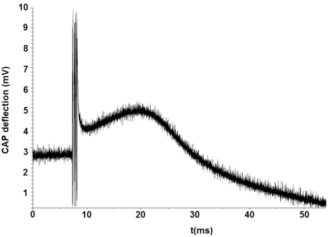
Measurements of compound action potential (CAP).
Discussion
The study is focused on improving the methods developed for the construction and crafting of a multi-electrode spiral stimulating nerve cuff capable of the selective activation of specific superficial regions of a nerve trunk as well as a certain degree of fibre-type selective stimulation. In particular, the purpose of the study was to test the hypothesis that spot welding, using a standard single pulse applied under optimum welding conditions, is a feasible technique for interconnections between platinum stimulating electrodes and stranded stainless-steel lead wires within the cuff. As a result, a thirty-three-electrode stimulation cuff for the selective activation of different superficial compartments, particularly within the vagus nerve, was manufactured.
In recent decades cuffs have been built that cover the size range from 2 to 5 mm ID and 14 mm length, with the number of active triplets from five to eleven5. In general, most nerve cuffs are manufactured using medical-grade silicone materials in combination with platinum foils that are connected to stainless-steel wires using different technologies. Nevertheless, there is still a lack of detailed metallurgical and electrochemical analyses regarding the technologies of interconnection. Therefore, the possibility of lead failure during prolonged nerve stimulation imposes some constraints on the use of these techniques for clinical applications.
Many different concepts for peripheral nerve interfaces have been developed and transferred into research or clinical applications with varying degrees of success. The major advantages of the technology deployed in the crafting are enhanced reliability, well-known body reactions, and the softness of the silicone sheets. In this relation, advances in vagus nerve stimulation have increased the need for nerve cuff designs that can selectively modulate the function of an internal organ via the selective stimulation of selected populations of nerve fibres9,18. Accordingly, the spiral-like arrangement of the cuff placed around the vagus nerve potentially allows an appropriately tight cuff-to-nerve contact. At the same time, the hypothesis that spiral cuff electrodes can be implanted with an internal diameter less than that of the nerve and expand to accommodate the vagus nerve without compression can be accepted. Therefore, with the goal of minimizing problems related to the cuffs and even improve their effectiveness, the technology of crafting on the basis of theoretical models as well as the appropriate technological solutions should be used.
Like with the majority of cuffs, the major disadvantages of the fabricated cuff are a relatively large cover of the nerve trunk, preventing natural circulation of the metabolites, rigidity and radial pressure. The more channels it has the more rigid is the whole cuff. Therefore, in crafting the cuff, the compressive action of the cuff and the potential chronic neuropathy possibly induced by the cuff should be carefully considered. In addition, the changed mechanical environment and the physiological movements of the tissue created by the presence of a cuff could have significant and acute effects on both the cuff’s performance and the nerve’s function64,65. Namely, responses to compressive effects could include axonal degeneration, demyelination, fibrosis, and are sometimes associated with a loss of electrophysiological function66. According to previous in-vivo testing of a cuff, the authors assumed that the pressures exerted by the developed cuff generate only a small amount of pressure, which is below the pressure required to occlude the blood flow in the nerves18,30,39.
One, very important, disadvantage is that the spatial selectivity strongly depends on the position of the electrodes relative to the nerve and its inner fascicles. It appears to be nearly impossible to selectively excite only the targeted few fibres in compound fascicles of, e.g., a vagus nerve using a cuff. Beside this, it was shown by Grill and Mortimer36 that the resistivity of the encapsulation tissue that surrounds cuffs chronically implanted on the sciatic nerve in adult cats for up to 8 months is sufficient to alter the shape and magnitude of the electric field generated by the chronically implanted electrodes. Furthermore, in certain circumstances, significant chemical reactions can occur during the electrical stimulation that can cause potentially destructive electrochemical effects on the welded interconnection between the platinum electrode and the stainless-steel lead wire. It was shown in the recent study of Pečlin et al.67, reviewing the electrochemical performance of a platinum electrode within a multi-electrode spiral nerve cuff, that the power spectral density of a quasi-trapezoidal, biphasic and current stimulating pulse, exhibits two main peaks, one at about 1 kHz and the other at about 2.5 kHz. The corresponding impedances for the two peaks are 600 Ω and 450 Ω, respectively. Therefore, the common resistance of wires leading to the single electrode triplet in the quasi-biphasic stimulating connection of 58 Ω is relatively low compared to the resistance of being in contact with the nervous tissue.
Nevertheless, the disadvantages are also the costs of their crafting, i.e., the cuffs are handcrafted and the costs rise in proportion to the number of stimulation electrodes due to the additional fabrication effort.
According to most of these constraints, the results of the present study are consistent with the published results of other investigators5,9,18,39. However, further research that would be necessary to answer the questions raised by the results could proceed in the following directions:
“in-vitro” flex bending fatigue testing to develop fatigue-life curves of the interconnections between the lead wires and the stimulating electrodes,
topological in-vitro assessments of the superficial properties of the welds using the electrochemical method of cyclic voltammetry instrumented with the reference electrode having a fine outside tip (diameter of 10 µm),
cuff designs to reduce the mechanical perturbations via the utilization of materials more closely suited to the mechanical properties of the nerve tissue and thus reduce the mechanical charge of the welded interconnections,
in-vivo studies to directly correlate acute function with chronic neural structure and function,
performing more experiments to show group statistics.
In conclusion, our findings emphasize the importance of mechanically reliable and electrochemically safe interconnections between a platinum stimulating electrode and a stainless-steel lead wire obtained using spot welding. The work presented has implications for nerve cuff design, implantation, and the prediction of long-term efficacy. It is imperative to understand all the problems related to the materials that may occur when a cuff is used for nerve stimulation over longer periods of time, which can sometimes be as long as 20 years.
We believe that the present study has contributed to the further development of cuffs to be used for the efficient and safe selective stimulation of autonomous peripheral nerves and for the selective recording of neural responses at the same time.
Acknowledgements
The authors acknowledge the financial support from the Slovenian Research Agency (research core funding No. (P3-0171)).
Author Contributions
J.R. developed the model for the selective activation of nerve fibres, developed the methods, technology and hardware, and prepared the manuscript. P.P. developed the model for the selective activation of the nerve fibres. S.R. revised the research methods. M.G. carried out microstructural analyses of the welds using scanning electron microscopy. J.B. analysed the structural properties of the spot welds. All the authors assisted with interpreting the data and discussed the results and commented on the manuscript.
Competing Interests
The authors declare that they have no competing interests.
Footnotes
Publisher's note: Springer Nature remains neutral with regard to jurisdictional claims in published maps and institutional affiliations.
Change history
11/19/2018
A correction to this article has been published and is linked from the HTML and PDF versions of this paper. The error has been fixed in the paper.
References
- 1.Naples G. G., Sweeny J. D. & Mortimer J. T. Implantable cuff, Method and manufacture, and Method of installation. (Inventors), U.S. Patent #4,602,624 (1986).
- 2.Stein RB, et al. Principles underlying new methods for chronic neural recording. Can. J. Neurol. Sci. 1975;2:235–244. doi: 10.1017/S0317167100020333. [DOI] [PubMed] [Google Scholar]
- 3.Peck RA. Cuff electrodes for chronic stimulation and recording of peripheral nerve activity. J. Neurosci. Methods. 1996;64:95–103. doi: 10.1016/0165-0270(95)00123-9. [DOI] [PubMed] [Google Scholar]
- 4.Malachowski K., Albert M. & Bartha J. W. Novel thin film cuff electrode for neural stimulation. Presented at the 26th Int’l Spring Seminar on Electronics Technology, Lesni, May 8–11 (2003).
- 5.Haugland M. A flexible method for fabrication of nerve cuff electrodes. Presented at the 18th Annual Int’l Conf IEEE Eng in Med & Biol Soc, Amsterdam, October-November 31–3 (1996).
- 6.Rodriguez FJ, et al. Polyimide cuff electrodes for peripheral nerve stimulation. J. Neurosci. Methods. 2000;98:105–118. doi: 10.1016/S0165-0270(00)00192-8. [DOI] [PubMed] [Google Scholar]
- 7.Sweeney JD, Ksienski DA, Mortimer JT. A nerve cuff technique for selective excitation of peripheral nerve trunk regions. IEEE Trans. Biomed. Eng. 1990;37:706–715. doi: 10.1109/10.55681. [DOI] [PubMed] [Google Scholar]
- 8.Goodall EV, deBreij JF, Holsheimer J. Position-selective activation of peripheral nerve fibres with a cuff electrode. IEEE Trans. Biomed. Eng. 1996;43:851–856. doi: 10.1109/10.508548. [DOI] [PubMed] [Google Scholar]
- 9.Choi AQ, Cavanaugh JK, Durand DM. Selectivity of Multiple-Contact Nerve Cuff Electrodes: A Simulation Analysis. IEEE Trans. Biomed. Eng. 2001;48:165–172. doi: 10.1109/10.909637. [DOI] [PubMed] [Google Scholar]
- 10.Schuettler M., Stieglitz T. & Meyer, J. U. A multipolar precision hybrid cuff electrode for FES on large peripheral nerves. Presented at the First Joint BMES/EMBS Conf, Atlanta, October 13–16 (1999).
- 11.Rozman J, Bunc M. Modulation of visceral function by selective stimulation of the left vagus nerve in dogs. Exp. Physiol. 2004;89:717–725. doi: 10.1113/expphysiol.2004.027953. [DOI] [PubMed] [Google Scholar]
- 12.Takaya M, Terry WJ, Naritoku DK. Vagus Nerve Stimulation Induces a Sustained Anticonvulsant Effect. Epilepsia. 2012;37:111–1116. doi: 10.1111/j.1528-1157.1996.tb01033.x. [DOI] [PubMed] [Google Scholar]
- 13.Veraart C, et al. Visual sensations produced by optic nerve stimulation using an implanted self-sizing spiral cuff electrode. Brain. Res. 1998;813:181–186. doi: 10.1016/S0006-8993(98)00977-9. [DOI] [PubMed] [Google Scholar]
- 14.Carlsten A, Folkow B, Hamberger CA. Cardiovascular effects of direct vagal stimulation in man. Acta. Physiol. Scand. 1957;41:68–76. doi: 10.1111/j.1748-1716.1957.tb01510.x. [DOI] [PubMed] [Google Scholar]
- 15.Bilgutay AM, Bilgutay IM, Merkel FK, Lillehei CW. Vagal tuning: a new concept in the treatment of supraventricular arrhythmias, angina pectoris, and heart failure. J. Thoracic. Cardiovas. Surg. 1968;56:71–82. [PubMed] [Google Scholar]
- 16.Carlson MD, et al. Selective stimulation of parasympathetic nerve fibres to the human sinoatrial node. Circulation. 1992;85:1311–1317. doi: 10.1161/01.CIR.85.4.1311. [DOI] [PubMed] [Google Scholar]
- 17.Zamotrinsky AV, Kondratiev B, de Jong JW. Vagal neurostimulation in patients with coronary artery disease. Auton. Neurosci. 2001;88:109–116. doi: 10.1016/S1566-0702(01)00227-2. [DOI] [PubMed] [Google Scholar]
- 18.Naples GG, Mortimer JT, Scheiner A, Sweeny JD. A spiral cuff electrode for peripheral nerve stimulation. IEEE Trans. Biomed. Eng. 1988;35:905–916. doi: 10.1109/10.8670. [DOI] [PubMed] [Google Scholar]
- 19.Grill WM, Mortimer JT. Stability of the Input-Output Properties of Chronically Implanted Multiple Contact Nerve Cuff Stimulating Electrodes. IEEE Trans. Rehab. Eng. 1998;6:364–373. doi: 10.1109/86.736150. [DOI] [PubMed] [Google Scholar]
- 20.Racz GB, Heavner JE. Comments, with Reply, on ‘A Spiral Nerve Cuff Electrode for Peripheral Nerve Stimulation’ by G.G. Naples Et Al. IEEE Trans. Biomed. Eng. 1989;36:1140–1141. doi: 10.1109/10.40823. [DOI] [PubMed] [Google Scholar]
- 21.Anholt TA, Ayal S, Goldberg JA. Recruitment and blocking properties of the CardioFit stimulation lead. J. Neural. Eng. 2011;8:034004. doi: 10.1088/1741-2560/8/3/034004. [DOI] [PubMed] [Google Scholar]
- 22.Tarver WB, George RE, Maschino SE, Holder LK, Wernicke JF. Clinical experience with a helical bipolar stimulating lead. Pacing. Clin. Electrophysiol. 1992;15:1545–56. doi: 10.1111/j.1540-8159.1992.tb02933.x. [DOI] [PubMed] [Google Scholar]
- 23.Battaini P. Electrolytic Etching for Microstructure Detection in Platinum Alloys. Platin. Met. Rev. 2011;55:71–72. doi: 10.1595/147106711X540706. [DOI] [Google Scholar]
- 24.Battaini P. Microstructure Analysis of Selected Platinum Alloys. Platin. Met. Rev. 2011;55:74–83. doi: 10.1595/147106711X554008. [DOI] [Google Scholar]
- 25.Wright JC. Jewellery-Related Properties of Platinum. Low thermal diffusivity permits use of laser welding for jewellery manufacture. Platin. Met. Rev. 2002;46:66–72. [Google Scholar]
- 26.Toyoda K., Miyamoto T., Tanihira T. & Sato H., inventors. Pilot Pen Co Ltd, High Purity Platinum and Its Production, Japanese Patent7/150,271; 1995.
- 27.Jeffus L. F. In Welding: Principles and Applications, 236–239, (Thomson Delmar Readings, Clifton Park, New York, USA, 2004).
- 28.Shannon G. Advances in Resistance Welding Technology Offer Improved Weld Quality and Reliability for Battery Manufacturers. Battery Power Products & Technology; 11(4) (2007).
- 29.Schrader G. F., Elshennawy A. K. & Lawrence E. In Manufacturing Processes & Materials, 311 (SME Publications, Dearborn, Michigan, USA, 2000).
- 30.Cuoco FA, Jr., Durand DM. Measurement of External Pressures Generated by Nerve Cuff Electrodes. IEEE Trans. Rehab. Eng. 2000;8:35–41. doi: 10.1109/86.830947. [DOI] [PubMed] [Google Scholar]
- 31.Ortler M, Unterhofer C, Dobesberger J, Haberlandt E, Trinka E. Complete removal of vagus nerve stimulator generator and electrodes. J. Neurosurg. Pediatr. 2010;5:191–194. doi: 10.3171/2009.9.PEDS0810. [DOI] [PubMed] [Google Scholar]
- 32.Gustafson KJ, et al. Fascicular anatomy of human femoral nerve: Implications for neural prostheses using nerve cuff electrodes. J. Rehabil. Res. Dev. 2009;46:973–984. doi: 10.1682/JRRD.2008.08.0097. [DOI] [PMC free article] [PubMed] [Google Scholar]
- 33.Micera S, et al. On the Use of Longitudinal Intrafascicular Peripheral Interfaces for the Control of Cybernetic Hand Prostheses in Amputees. IEEE Trans. Neural. Syst. Rehabil. Eng. 2008;16:453–472. doi: 10.1109/TNSRE.2008.2006207. [DOI] [PubMed] [Google Scholar]
- 34.Sahin M, Durand DM. Improved nerve cuff electrode recordings with subthreshold anodic currents. IEEE. Trans. Biomed. Eng. 1998;45:1044–1050. doi: 10.1109/10.704873. [DOI] [PubMed] [Google Scholar]
- 35.Navarro X, et al. A critical review of interfaces with the peripheral nervous system for the control of neuroprostheses and hybrid bionic systems. J. Peripher. Nerv. Syst. 2012;10:229–258. doi: 10.1111/j.1085-9489.2005.10303.x. [DOI] [PubMed] [Google Scholar]
- 36.Grill WM, Mortimer JT. Neural and connective tissue response to long-term implantation of multiple contact nerve cuff electrodes. J. Biomed. Mater. Res. 2000;50:215–226. doi: 10.1002/(SICI)1097-4636(200005)50:2<215::AID-JBM17>3.0.CO;2-A. [DOI] [PubMed] [Google Scholar]
- 37.Gupta R, Rowshan K, Chao T, Mozaffar T, Steward O. Chronic nerve compression induces local demyelination and remyelination in a rat model of carpal tunnel syndrome. Exp. Neurol. 2004;187:500–508. doi: 10.1016/j.expneurol.2004.02.009. [DOI] [PubMed] [Google Scholar]
- 38.Topp KS, Boyd BS. Structure and Biomechanics of Peripheral Nerves: Nerve Responses to Physical Stresses and Implications for Physical Therapist Practice. Phys. Ther. 2006;86:92–109. doi: 10.1093/ptj/86.1.92. [DOI] [PubMed] [Google Scholar]
- 39.Caparso AV, et al. A Nerve Cuff Electrode for Controlled Reshaping of Nerve Geometry. J. Biomater. Appl. 2009;24:247–273. doi: 10.1177/0885328208097426. [DOI] [PMC free article] [PubMed] [Google Scholar]
- 40.McNeal DR, Baker LL, Symons JT. Recruitment Data for Nerve Cuff Electrodes: Implications for Design of Implantable Stimulators. IEEE Trans. Biomed. Eng. 1989;36:301–308. doi: 10.1109/10.19851. [DOI] [PubMed] [Google Scholar]
- 41.Goodall EV, Kosterman LM, Holsheimer J, Struijk JJ. Modeling study of activation and propagation delays during stimulation of peripheral nerve fibers with a tripolar cuff electrode. IEEE Trans. Rehab. Eng. 1995;3:272–282. doi: 10.1109/86.413200. [DOI] [Google Scholar]
- 42.Fang ZP, Mortimer JT. Selective activation of small motor axons by quasitrapezoidal current pulses. IEEE Trans. Biomed. Eng. 1991;38:168–179. doi: 10.1109/10.76383. [DOI] [PubMed] [Google Scholar]
- 43.Butson CR, Miller IO, Normann RA, Clark GA. Selective neural activation in a histologically derived model of peripheral nerve. J. Neural. Eng. 2011;8:036009. doi: 10.1088/1741-2560/8/3/036009. [DOI] [PubMed] [Google Scholar]
- 44.Gasser HS. The classification of nerve fibers. Ohio J. Sci. 1941;41:145–159. [Google Scholar]
- 45.Schnitzlein HN, Rowe LC, Hoffman HH. The myelinated component of the vagus nerve in man. Anat. Rec. 1958;131:649–666. doi: 10.1002/ar.1091310404. [DOI] [Google Scholar]
- 46.Hoffman HH, Schnitzlein HN. The numbers of nerve fibres in the vagus nerve of man. Anat. Rec. 1961;139:4291958435. doi: 10.1002/ar.1091390312. [DOI] [PubMed] [Google Scholar]
- 47.Veltink PH, Van Veen BK, Struijk JJ, Holsheimer J, Boom HBK. A model study of nerve fasicle stimulation. IEEE Trans. Biomed. Eng. 1989;36:683–692. doi: 10.1109/10.32100. [DOI] [PubMed] [Google Scholar]
- 48.McNeal DR. Analysis of a model for excitation of myelinated nerve. IEEE. Trans. Biomed. Eng. 1976;23:329–337. doi: 10.1109/TBME.1976.324593. [DOI] [PubMed] [Google Scholar]
- 49.Rattay F. Analysis of models for external stimulation of axons. IEEE. Trans. Biomed. Eng. 1986;33:974–977. doi: 10.1109/TBME.1986.325670. [DOI] [PubMed] [Google Scholar]
- 50.Veltink PH, Van Alste JA, Boom HBK. Influences of stimulation conditions on recruitment of myelinated nerve fibers: A model study. IEEE. Trans. Biomed. Eng. 1989;35:917–924. doi: 10.1109/10.8671. [DOI] [PubMed] [Google Scholar]
- 51.Pečlin P, Rozman J. Alternative paradigm of selective vagus nerve stimulation tested on an isolated porcine vagus nerve. The Scientific World Jo. 2014;1:310283. doi: 10.1155/2014/310283. [DOI] [PMC free article] [PubMed] [Google Scholar]
- 52.Pečlin P., Ribarič S., Podbregar M., Podpečan O., Rozman J. Selective electrical stimulation and recording of an isolated porcine vagus nerve. Presented at the SNC’17 Thematic Symposia SiNAPSA Neuroscience Conference ‘17, Ljubljana, September 29–30, (2017).
- 53.Geddes LA, Roeder R. Criteria for the selection of materials for implanted electrodes. Ann. Biomed. Eng. 2003;31:879–890. doi: 10.1114/1.1581292. [DOI] [PubMed] [Google Scholar]
- 54.Hudak EM, Mortimer JT, Martin HB. Platinum for neural stimulation: voltammetry considerations. J. Neural. Eng. 2010;2:26005. doi: 10.1088/1741-2560/7/2/026005. [DOI] [PubMed] [Google Scholar]
- 55.Robblee L. S. & Rose T. L. In Neural Prostheses: Fundamental Studies. 25–66 (Prentice-Hall, Englewood Cliffs, New Jersey, USA 1990).
- 56.Robblee L. S. & Rose T. L. The electrochemistry of electrical stimulation. Presented at the 12th Ann. Conf IEEE Eng in Med & Biol Soc, Philadelphia, November 1–4 (1990).
- 57.Brummer SB, Turner MJ. Electrochemical considerations for safe electrical stimulation of the nervous system with platinum electrodes. IEEE. Trans. Biomed. Eng. 1977;24:59–63. doi: 10.1109/TBME.1977.326218. [DOI] [PubMed] [Google Scholar]
- 58.Official Journal of the European Union, Commission Directive 2004/96/EC, 27 September, 2004, EU, 28.9.2004, pp. L 301/51–L 302/52.
- 59.Loginov YN, Yermakov AV, Grohovskaya LG, Studenok GI. Annealing Characteristics and Strain Resistance of 99.93 wt.% Platinum. Implications for the manufacture of platinum artefacts. Platin. Met. Rev. 2007;51:178–184. doi: 10.1595/147106707x237708. [DOI] [Google Scholar]
- 60.Savitsky EM. Handbook of Precious Metals. New York, USA: Hemisphere Publishing Corp; 1989. [Google Scholar]
- 61.Unskov EP, et al. Theory of Plastic Deformations of Metals. Mashinostroenie, Moscow: USSR; 1983. [Google Scholar]
- 62.Biggs T, Taylor SS, van der Lingen E. The Hardening of Platinum Alloys for Potential Jewellery Application. Platin. Met. Rev. 2005;49:2–15. doi: 10.1595/147106705x2440. [DOI] [Google Scholar]
- 63.Aulova A., Rozman J. & Emri I. Nanoindentation hardness and elastic modulus of cold-rolled and differently post-processes platinum ribbons for implantable electrodes. Presented at the19th International Workshop on Advances in Experimental Mechanics, Portorož, August 16–22 (2015).
- 64.Restaino SM, Abliz E, Wachrathit K, Krauthamer V, Shah SB. Biomechanical and functional variation in rat sciatic nerve following cuff electrode implantation. J. Neuroeng. Rehabil. 2014;11:73. doi: 10.1186/1743-0003-11-73. [DOI] [PMC free article] [PubMed] [Google Scholar]
- 65.Highet WB, Sanders FK. The effects of stretching nerves after suture. Br. J. Surg. 2012;30:355–369. doi: 10.1002/bjs.18003012012. [DOI] [Google Scholar]
- 66.Thil M-A, Duy DT, Colin IM, Delbeke J. Timecourse of tissue remodelling and electrophysiology in the rat sciatic nerve after spiral cuff electrode implantation. J. Neuroimmunol. 2007;185:103–114. doi: 10.1016/j.jneuroim.2007.01.021. [DOI] [PubMed] [Google Scholar]
- 67.Pečlin P, Mehle A, Karpe B, Rozman J. Electrochemical and electrophysiological performance of platinum electrodes within the ninety-nine-electrode stimulating nerve cuff. Artif. Organs. 2015;39:886–896. doi: 10.1111/aor.12625. [DOI] [PubMed] [Google Scholar]