Abstract
One of the factors proposed to regulate the eye growth is the error signal derived from the defocus in the retina and actually, this might arise from defocus not only in the fovea but the whole visual field. Therefore, myopia could be better predicted by spatio-temporally mapping the ‘environmental defocus’ over the visual field. At present, no devices are available that could provide this information. A ‘Kinect sensor v1’ camera (Microsoft Corp.) and a portable eye tracker were used for developing a system for quantifying ‘indoor defocus error signals’ across the central 58° of the visual field. Dioptric differences relative to the fovea (assumed to be in focus) were recorded over the visual field and ‘defocus maps’ were generated for various scenes and tasks.
OCIS codes: (120.5710) Refraction; (330.7333) Visual optics, refractive anomalies; (150.4232) Multisensor methods
1. Introduction
The prevalence of myopia has increased in many countries over the last few decades [1]. The awareness of the ‘march of myopia’ [2] reached not only the scientific community but also the general public. As indicated by the number of papers published per year, the amount of research on myopia has increased tenfold since 1980 (1980: 100 papers, 2016: 1000 papers in PubMed); however, why myopia develops in school-aged children and why it is not self-limiting, remains unknown. Since the aetiology of myopia is multifactorial [3], a holistic view has to be established to solve this problem.
Eye growth is known to be visually guided by a closed feedback loop that uses defocus of retinal images as an error signal, which might induce structural changes in the choroid and sclera. The operation of the closed-loop control of refractive development can be reliably observed in animal models where myopia or hyperopia can be induced by imposing negative defocus or positive defocus using spectacle lenses [4].
Experiments in chicks, guinea pigs, and monkeys have shown that locally imposed defocus induces changes in eye growth selectively in the defocused parts of the posterior globe [5]. Furthermore, it was shown that, in monkeys, defocus imposed only on the periphery is sufficient to change refractive development in the fovea [6,7].
In humans, peripheral refractive errors (the dioptric errors present inside the eye, owing to the different refraction on the periphery) vary systematically with the foveal refractive error. For example, myopic eyes are known to have more hyperopic refractive errors in their periphery relative to the fovea [8], while relative peripheral myopia is found usually in emmetropes or hyperopes. It was proposed that this condition could potentiate the development of refractive errors as a positive feed-forward system [9]. It was also proposed that intentionally imposed peripheral myopic defocus (defocusing of the peripheral refraction) could reduce the progression and perhaps the onset of myopia [10]. However, it could not be excluded that the peripheral refraction is more a consequence rather than a cause of the foveal refractive error development [11].
The role of the peripheral refractive errors in the development of foveal refractive errors is still not clear [12]. Peripheral defocus varies profoundly and also depends on the visual environment, but so far only a few publications have analysed the defocus error signals in different visual environments. For instance, Flitcroft [13] simulated defocus over the visual field (‘the environmental defocus’) during a number of visual tasks. However, the theoretical approach presented in [13] accounted neither for temporal variations of the scene nor for temporal summation. An experimental approach was implemented by Sprague and colleagues [14], who presented the first procedure to map out the defocus blur from scenes into the eye. The method relied on the disparities detected by stereo cameras but was limited to the central 10° around the fovea and did not include peripheral positions assumed to be important for emmetropisation (20°–40°) [15].
A novel method to map out the average defocus signals for various indoor tasks is presented here. The approach includes measurements of eye movements and possible changes over time (assuming that the accommodation keeps the foveal image in focus), resulting in dioptric defocus maps covering ± 29° of the horizontal and ± 23° of the vertical visual field.
2. Materials & methods
2.1 Equipment
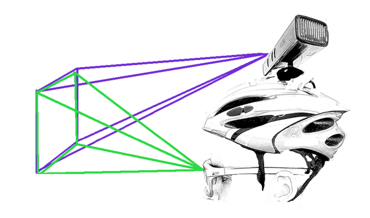
To map out depth information, a commercial device was used that is capable to obtain depth information from a scene (Kinect sensor v1 for PC (Microsoft Corp., Redmond, WA, USA)), in conjunction with a commercial eye-tracker (ETG 2.6 Recording Unit (SensoMotoric Instruments GmbH, Teltow, Germany)) to log the fixation information (Fig. 1).
Fig. 1.
Subject wearing the eye tracker and the helmet with the Kinect sensor fixed at the top. The purple rays refer to Kinect while the green ones refer to the Eye Tracker. The Kinect sensor can modify the subtending angle so that it can be adapted to the subject’s physiognomy.
RGB-Depth sensors, such as Kinect, can record not only RGB values of each pixel but also its depth values in space. The Kinect sensor consists of a conventional RGB camera and an infrared (IR) camera that analyses 34815 [16] random IR spot patterns that are projected to the surrounding space by an IR emitter, and a detector triangulates the distances based on the positions of the IR spots. The sensor’s depth is in the 40–450 cm range [17], while some studies found an even larger range, with depth data recorded up to 600 cm [18]. To measure distances shorter than 40 cm, as done in the current study, the Kinect sensor was mounted on the back of a helmet, which reduced the smaller detectable distance to ~30 cm (Fig. 1). The reliability of the Kinect camera with respect to depth measurements has been confirmed before [18–20].
To record defocus maps in retinal coordinates rather than environmental coordinates, the axis of fixation has to be taken into account and a commercially available, portable eye tracker, the ETG 2.6 Recording Unit (SensoMotoric Instruments GmbH, Teltow, Germany), was used for accomplishing this task. The eye tracker was connected to a mobile phone and provided the angles of fixation, pupil size, and a video of the scene [21].
Specifications of the used devices are summarised in Table 1 .
Table 1. Summary of the different specifications of the sensors used.
| Kinect |
Eye Tracker |
|||
|---|---|---|---|---|
| Channel | RGB | Depth | Camera | Sampling of tracker |
| Resolution | 640 × 480 (default) 1280 × 960 (max.) |
640 × 480 | 960 × 720 | - |
| Horizontal FoVa | 62° | 58,5° | 60° | 80° |
| Vertical FoV | 48,6° | 46,6° | 46° | 60° |
| Max Frequency | 30 FPSb (default) 12 FPS (max. resolution) |
30 FPS | 30 FPS | 60/120 Hz |
FoV (Field of View).
FPS (Frames per second). Data from Kinect obtained from the SDK.
2.2 Recording
In the first step, the environment was recorded while the subject wore the helmet with the Kinect sensor attached and the eye tracker, as shown in Fig. 1. The number of frames recorded using the Kinect sensor was 900, which is equivalent to around 5 min of recording time using this sensor, and this was controlled using MATLAB. While the eye tracker was recording, the subject was asked to look at the monitor until the first frame from the Kinect preview was displayed. After this initial step, the subject was allowed to freely move and look around until an auditory feedback indicated that the last 15 frames had started. Then, the subject was asked to look back at the monitor to record the screen at the time when the last frame from the Kinect last frame of preview was shown. At this point, the eye tracker stopped recording.
2.3 Computational analysis of defocus maps
To obtain the ‘defocus maps’ or the ‘dioptric 3D space’ [22] from indoor scenes, the device synchronisation and the post-processing computations were performed using MATLAB 2017a (The MathWorks Inc., Natick, MA, USA).
2.3.1 Synchronisation of the number of frames
The RGB-D sensor (Kinect camera) was controlled using MATLAB; hence, the Kinect depth and RGB frames were directly available for further processing. However, the eye tracker data needed to be exported using its own proprietary software: ‘BeGaze’ (SensoMotoric Instruments GmbH, Teltow, Germany).
Since a perfect synchronisation of the recording frequencies of the different devices was not possible in the current setup, manual frame by frame synchronisation was performed. The frames of the eye tracker that contained the first and last previews of the frames provided by the Kinect camera, were selected by an operator and used to crop the duration of the video and the fixation point data from the eye tracker.
Although the data exported from the eye tracker were acquired at the lowest available frame rate in the ‘BeGaze’ software, there was still some discrepancy between the frame rates of both devices (eye tracker: 10 FPS; Kinect: ~2.5 FPS). To align the frame rates of the two data streams, the number of frames recorded using the Kinect device was divided by the number of frames recorded using the eye tracker, to obtain a single factor. A similar procedure was required for the fixation point data exported from the eye tracker, to match the number of measured fixations to the number of frames.
The final number of frames and fixation values from the eye tracker was forced to coincide with the number of frames recorded using the Kinect device.
2.3.2 Matching the coordinates in the space
The fact that the specifications of both devices differed (as noted in Table 1) and that there were differences in the spatial positions between the two devices (shown in Fig. 1), made coordinate matching difficult. Therefore, frame-specific matching was performed prior to the step, where distances were operated or extrapolated between the devices.
To match the fixation coordinates to the Kinect device’s frames, the differences in the resolution of the two video channels had to be taken into account. The resolutions were aligned using the MATLAB in-built function imresize, using a factor of 0.667 to map frames with a resolution of 960 × 720 pixels onto frames with a resolution of 640 × 480 pixels.
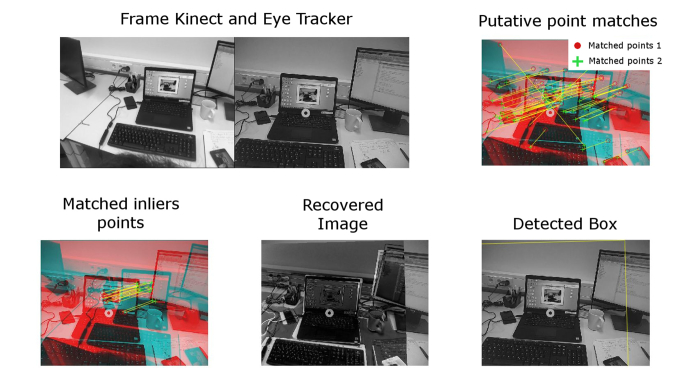
To adjust the different fields of view of the two devices, the Computer Vision System Toolbox in MATLAB (The MathWorks Inc., Natick, MA, USA) was used, as shown in Fig. 2. First, the putative points from the images of the RGB channels from the Kinect device and the eye tracker were matched using the SURF points extraction tool in the Computer Vision System Toolbox [23]. Next, the MATLAB function estimateGeometricTransform (also provided within the Computer Vision Toolbox and using the MSAC algorithm [24]) was used to detect points that were classified as inliers that could be processed further and points that were classified as outliers and needed to be excluded from further analysis. Finally, the gaze positions were shifted to the Kinect frame coordinates, using the same MATLAB function (estimateGeometricTransform).
Fig. 2.
Illustration of the procedure to obtain the geometrical transformation function to shift the fixation coordinates from the eye-tracker plane to the Kinect plane, using the MATLAB Computer Vision Toolbox (c). The picture on the upper left illustrates the difference between the scenes recorded using the eye tracker and the Kinect device. The upper right and bottom left pictures show both inputs superimposed, including putative points that were identified by the SURF algorithm. Pictures on the bottom left and centre show how the eye tracker image is superimposed on, and then matched to the Kinect image after applying a geometrical transformation.
The obtained transformation function (a two-dimensional (2D) geometrical polynomial) was used to recover the ‘foveal position’ in the Kinect device’s frames that could be mapped onto the fixation coordinates obtained using the eye tracker.
2.3.3 Obtaining the map
The Kinect sensor could not collect data for areas of the scene with specular reflections. These areas were refilled using the Karl Sanford algorithm that complemented the missing depth information, using a statistical method relying on the 25 surrounding pixels [25]. This step was applied prior to using the pixel depth values from the Kinect device.
For each set of frames out of 900 (including the Kinect-Depth, Kinect-RGB, and Eye Tracker-RGB), a relative dioptric depth map was obtained by translocating all the scene pixel points from the coordinates obtained using the eye tracker into the coordinates of the Kinect device, using a previously obtained transformation function and calculating the relative depth from each pixel to the fixation/foveal point. When the fixation point was outside of the field of view of the Kinect depth map or lacking, for instance owing to a blink, the corresponding frames were excluded from the analysis.
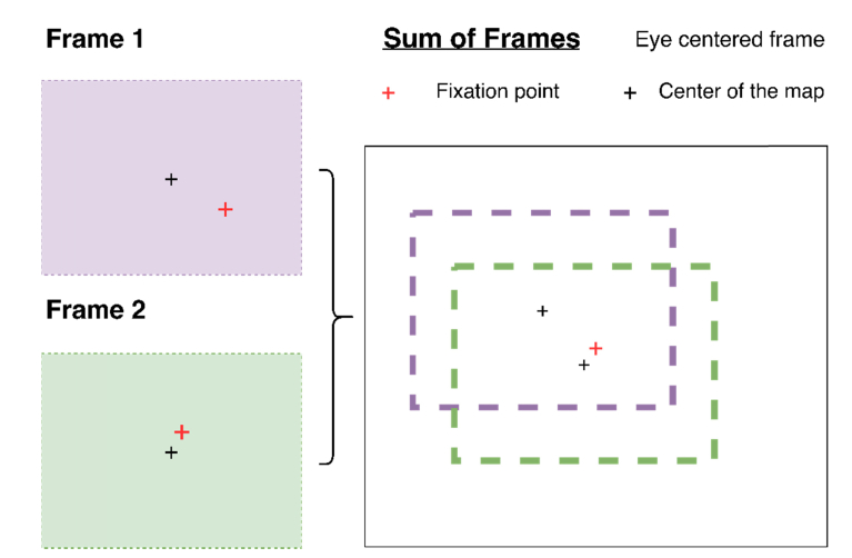
As the eye tracker was centered to the head and not to the eye position, the recorded gaze positions were not centered with respect to the Kinect camera’s field of view. Assuming foveal fixation, the coordinates of each pixel were re-mapped using the foveal point as a fix point, as shown in Fig. 3.
Fig. 3.
Illustration of the process in which the fixation map provided by the eye tracker (and centered to the measured eye) is remapped to the output provided by the Kinect camera.
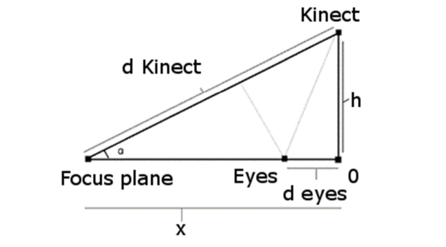
In spite of all the shifts to which the maps were subjected, they were referred to the Kinect plane rather than the position of the eyes (see Fig. 4 for a schematic). To obtain the resulting depth information from the eyes’ position, trigonometric equations, Eq. (1) and Eq. (2), were applied to obtain the real distances to the eyes.
| (1) |
| (2) |
Finally, after centering the frames and distances to the eyes, the average differences in depth between fixated objects and peripheral objects were converted into diopters and used to obtain the dioptric defocus maps.
Fig. 4.
Schematic distance between the eyes and the Kinect camera.
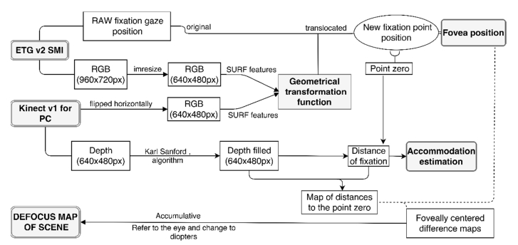
The new defocus maps were not only able to represent the sign of defocus in the visual field, but also the amount of defocus in diopters that arrived at the eyes over time. The procedure is shown schematically in Fig. 5.
Fig. 5.
Diagram of the procedure for obtaining the defocus map.
3. Results
3.1 Validation
Prior to performing measurements of different scenes, the depth estimations provided by the Kinect camera were validated. Five objects in two different environments were measured three times using the Kinect device and a metric tape, the resultant 30 measurements were evaluated, and the correlation and the slope values obtained are reported in Table 2.
Table 2. Correlation and slope values comparing the Kinect device with a metric tape.
| Methods | Correlation (Rho-value, R2) |
p-value |
(y = mx + b)
m = slope |
|---|---|---|---|
| Metric tape- Kinect1 | 0.9998 | 1.8e-50 | 1.0087x - 7.8357 |
| Metric tape- Kinect with filled frames2 | 0.9999 | 8.9e-52 | 1.006x - 2.9106 |
| Kinect1- Kinect with filled frames2 | 0.9984 | 1.9e-47 | 0.997x + 5.4824 |
Original depth frames.
Frames from Kinect after processed with Karl Sanford’s algorithm.
The results reveal high correlations and indicate that the device can be used for the presented application.
3.2 Original data recorded
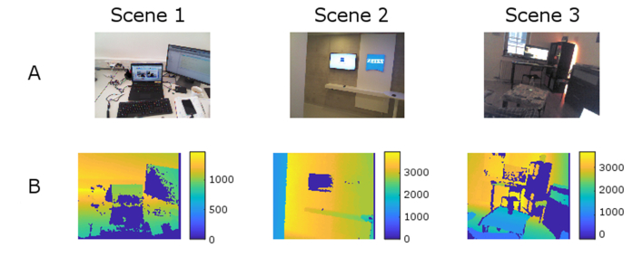
The method was tested using different indoor environments on only one subject. Each scene was recorded twice (in different sessions), as variations between these two sessions were expected, owing to the fact that the subject was allowed to move and look wherever he wished. For each session, 4–5 min (900 frames) were recorded using the Kinect camera and logged to MATLAB. To demonstrate the usefulness and the potential applications of the developed method, three different typical indoor scenes were recorded and analysed. Scene #1 corresponded to a contemporary workspace, while Scene #2 represented a corridor, where walls limited the vision on both sides in a close environment. Finally, Scene #3 represented a small living room, where the subject was watching TV.
The characteristics of the recorded scenes, such as the number of frames used to compute the final map, the duration of the recording session, and the average distance of the fixation gaze, are summarised in Table 3.
Table 3. Summary of different aspects of the environments recorded.
| Scene | 1A | 1B | 2A | 2B | 3A | 3B |
|---|---|---|---|---|---|---|
| Frames captured using the Kinect device |
900 | 900 | 900 | 900 | 900 | 900 |
| Frames captured using the eye tracker |
1276 | 1176 | 1268 | 1327 | 1290 | 1133 |
| Estimated duration of recording (min:ss) |
4:15 | 3:55 | 4:17 | 4:05 | 4:18 | 3:46 |
| Computed frames for final defocus map |
773 | 697 | 811 | 841 | 655 | 785 |
| Average focus plane from the computed frames (mm from Kinect) |
1252 | 1071 | 3423 | 3535 | 2775 | 2621 |
| Average distance from eyes to focus plane (mm) |
1147 | 966 | 3318 | 3430 | 2670 | 2516 |
| Maximal variation in the range of fixation (m) |
>6 | >6 | 3.1 | 3 | 2.7 | 2.6 |
| Estimated average accommodation (diopters) |
0.87 | 1.04 | 0.3 | 0.29 | 0.37 | 0.4 |
For better understanding of the recorded scenes, representative frames are shown in Fig. 6, along with their corresponding depth maps/frames that were obtained using the Kinect sensor.
Fig. 6.
Representative frames of the scenes acquired using the Kinect camera. (A) RGB channel. (B) Depth channel. Dark blue areas represent lost pixels owing to poor reflectivity before filling them with the Karl Sanford algorithm [25].
3.3 Defocus maps
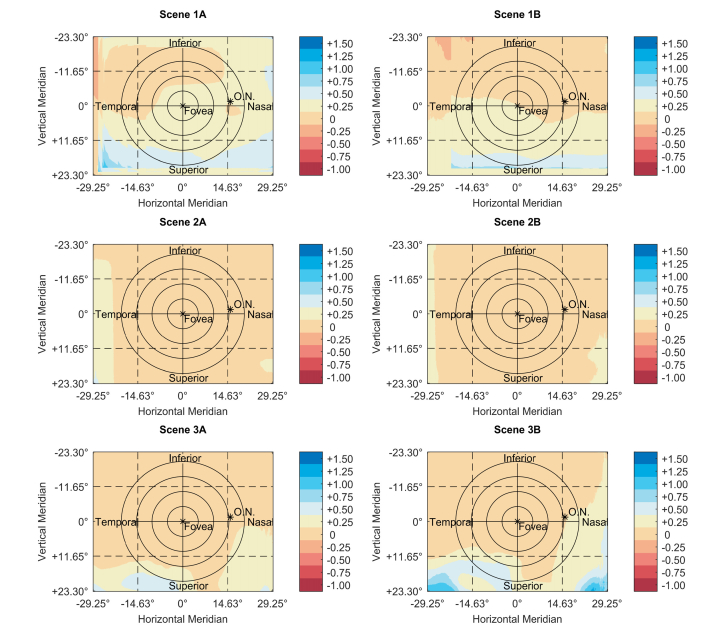
The final maps, obtained using the above-described method, are shown in Fig. 7. This figure shows maps with the distribution of the defocus signal across the visual field in diopters.
Fig. 7.
Dioptric defocus maps of the subject’s right eye along with scale bars (diopters) and grids with degrees for better understanding of the spatial distribution over the eye. The colour maps are based on the ones proposed by Light and Bartlein [26]. In addition, the position of the optic nerve (O.N.) is sketched according to literature-based approximations [27]. Concentric circles are marked as a reference around the fovea in steps of 5°.
3.4 Distributions of defocus for various scenes
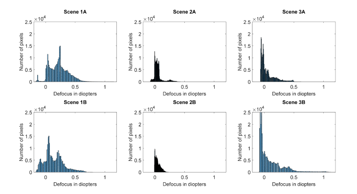
Comparing intersession (intra-scene) variations, the distributions of the recorded pixels for different defocus values provide useful information on the extent of the defocus variation across the two sessions, for the same scene. The different scenes and their repetition distributions are summarised in Fig. 8.
Fig. 8.
Histograms showing the distributions of the defocus values versus the number of pixels. (x = defocus in diopters, y = number of pixels containing that value of defocus). Panels A and B refer to the same scene recorded at different times and susceptible to small variations across the tasks.
Figure 8 shows the number of pixels (out of 307.200) for a resolution of 640 × 480 pixels that have the same extent of defocus. They are represented without considering the area in which they appeared.
4. Discussion
Assuming that the peripheral refractive errors provide a signal that triggers not the onset [28] but the progression of myopia [11], the presented method describes an approach to analyse the peripheral environmental defocus input across the visual field.
4.1 Reliability of the depth estimations
Validation of the Kinect camera for measuring the depth of scenes yielded highly correlated outcomes and the results obtained are adequate in terms of depth estimation for the proposed research. In addition, the results appear to be as reliable as those of metric tape measurements. Some other studies have shown less reliable results with a standard deviation of up to 25 mm for a recording distance of 2 m [18]. However, even within that range of standard deviations, the uncertainty of defocus is only on the order of centimetres. Furthermore, in accordance with the already published literature, it can be concluded that the device is feasible and sufficiently reliable for biomedical applications [18–20].
4.2 The original data
The number of frames that were recorded during the same sessions of each scene reveals some variability between the data obtained using the different devices. The main reasons for the observed differences are the head movement (especially fast movement), blinks, or the fact that the gaze position was sometimes out of the measurable visual field. Differences in the time used for logging are accountable to the limited amount of random access memory (RAM) available on the computer at the point of the measurement. Additional differences between the sessions are also caused by the fact that the subject was allowed to move freely.
4.3 Level of defocus depending on the scene and the distribution of defocus
To study the dissimilarities in the extent of defocus over time for the same scene, all three scenes were recorded twice. As can be observed from Fig. 7, the distribution of the pixels that contain the same amount of defocus can differ for the same scene. As for the original data (Section 3.2), the observed variability can be attributed to the continuous movement of the subject’s eyes and the freedom of the subject to look and move around without restrictions.
Nevertheless, as shown in Fig. 8, the variations in the distribution of defocus over the 900 frames have similar profiles, and it is plausible that longer measurements can reduce those variations.
In line with Sprague et al. [14], the current results suggest that stronger blurring is more likely to occur when fixation is located on near objects, compared with the situation when fixation is on distal objects. The same authors also concluded that defocus of more than ± 0.5 diopters is highly unexpected. The results of the current study suggest that such levels of defocus are uncommon for the near periphery, but they can appear for the lower (superior if referred to the retinal level) visual fields. The observed differences might be attributed to the fact that Sprague et al. restricted the field of view to the central 20° ( ± 10° around the fovea).
The fact that the levels of defocus measured in the current study were smaller than the central noticeable threshold that was reported by Wang and colleagues [29] suggests that the neural system likely plays only a minor role in the development and progression of myopia, as it was suggested earlier, being almost an exclusive role of the retina ‘per se’ [30–32]. Nevertheless, this conclusion cannot be extrapolated from the present study and further research is required to confirm this point, especially when the fact is taken into account that the amount of peripheral defocus depends on the central refractive error (especially in highly myopic eyes). In that case, peripheral defocus that originates from the depth of the environmental objects, may only play a minor role in people with fast progression of their myopic refractive errors. On the other hand, environmental defocus could play a greater role in the onset of myopia as peripheral refractive errors reported in emmetropes and hyperopes have smaller magnitudes [33].
Besides the pilot nature of this study, illustrating the development of a new system for modelling the on and off-axis defocus arriving to our eyes, a common factor was observed over the scenes recorded. Positive defocus appears to be more present than negative defocus, across the indoor tasks/scenes shown in Fig. 8.
More scenes and tasks need to be recorded to develop a better overall idea of the dioptric distribution for indoor environments, especially considering that North Americans, for example, spend more than 86% of their daily time indoors, according to the National Human Activity Pattern Survey (NHAPS) [34,35].
4.4 Limitations and future steps
The limitations of the present approach are outlined below.
- The reliability of the used method is based on IR structures, which limits its usage to indoor environments (where IR is not present) or to places in which IR is at least not as strong as outdoors. Nevertheless, the results of the current study have shown that the use of such a method to measure dioptric defocus maps outdoors might not be very relevant. Large dioptric differences are only achievable for very close objects and environments. It is difficult to find outdoor scenes with objects closer than 1 m, so dioptric differences can be expected to be much smaller than indoors.
- Although it was not possible to compare outdoor and indoor environments owing to the above limitation, some other approaches (such as stereo cameras) can deal with such limitations. However, they compute distance matching based on the discrepancy between their cameras, which is fixed and may result in less precise depth estimations. Furthermore, the proposed approach measures depth using readily available commercial devices while other setups may require more technical equipment.
- Objects that are closer than 30 cm would be omitted as the device cannot handle smaller distances. Nevertheless, it is not uncommon nowadays to find teenagers using their mobile devices at distances smaller than 30 cm. However, it was not possible to go below this range, as with the current setup, the head/helmet would have restricted the visual field of the Kinect camera. Nevertheless, up-coming generations of RGB-D sensors will be able to solve this limitation in the near future, allowing researchers to increase the range of distances that can be measured.
- In addition, it should be considered that those maps represent the level of defocus that arrives to the eyes, and not to the retinal level. The internal refraction of light is highly individual, especially when one considers peripheral refractive errors. To improve these maps, and to determine what exactly happens to the error signal that arrives at the retina, posterior individualisation of the maps is needed, by measuring, mapping and applying the peripheral refraction profiles of the subjects’ eyes to them. One still should keep in mind that even with such individualisation, other factors such as the lag of accommodation (that is often reported in myopic children), can make a direct transformation of the dioptric field space into a retinal dioptric defocus map unreliable.
5. Conclusions
With the obtained results regarding the level of defocus that arrives to the eye in the used scenes, it was shown that our daily environment is not dioptrically uniform. The results suggest that it is important not only to understand and investigate the foveal and peripheral error signals that influence the emmetropisation feedback loop but also to study the role of the scene input. With the presented setup, a step forward was taken, to better describe the three-dimensional dioptric space and to understand how the dissimilarities related to it provoke different defocus signals.
6. Supplementary materials
The software used in this study can be delivered upon request, under a Creative Commons License (CC-BY).
Funding
European Union’s Horizon 2020 research and innovation programme under the Marie Skłodowska-Curie grant agreement No 675137
Disclosures
The authors declare that there are no conflicts of interest related to this article.
This work was done in an industry-on-campus-cooperation between the University Tuebingen and Carl Zeiss Vision International GmbH. The work was supported by the European Grant Agreement as noted in the Funding section (F). F. Schaeffel is a scientist at the University Tuebingen, M. García, A. Ohlendorf and S. Wahl are employed by Carl Zeiss Vision International GmbH (E) and are scientists at the University Tuebingen.
References and links
- 1.Holden B. A., Fricke T. R., Wilson D. A., Jong M., Naidoo K. S., Sankaridurg P., Wong T. Y., Naduvilath T. J., Resnikoff S., “Global Prevalence of Myopia and High Myopia and Temporal Trends from 2000 through 2050,” Ophthalmology 123(5), 1036–1042 (2016). 10.1016/j.ophtha.2016.01.006 [DOI] [PubMed] [Google Scholar]
- 2.Dolgin E., “The myopia boom,” Nature 519(7543), 276–278 (2015). 10.1038/519276a [DOI] [PubMed] [Google Scholar]
- 3.Dirani M., Shekar S. N., Baird P. N., “Adult-onset myopia: The Genes in Myopia (GEM) twin study,” Invest. Ophthalmol. Vis. Sci. 49(8), 3324–3327 (2008). 10.1167/iovs.07-1498 [DOI] [PubMed] [Google Scholar]
- 4.Wallman J., Winawer J., “Homeostasis of eye growth and the question of myopia,” Neuron 43(4), 447–468 (2004). 10.1016/j.neuron.2004.08.008 [DOI] [PubMed] [Google Scholar]
- 5.Totonelly K., Coletta N. J., “Eye shape and peripheral refractive error in the development of myopia,” The New England College of Optometry (2010). [Google Scholar]
- 6.Smith E. L., Kee C.-S., Ramamirtham R., Qiao-Grider Y., Hung L.-F., “Peripheral vision can influence eye growth and refractive development in infant monkeys,” Invest. Ophthalmol. Vis. Sci. 46(11), 3965–3972 (2005). 10.1167/iovs.05-0445 [DOI] [PMC free article] [PubMed] [Google Scholar]
- 7.Schippert R., Schaeffel F., “Peripheral defocus does not necessarily affect central refractive development,” Vision Res. 46(22), 3935–3940 (2006). 10.1016/j.visres.2006.05.008 [DOI] [PubMed] [Google Scholar]
- 8.Hoogerheide J., Rempt F., Hoogenboom W. P., “Acquired myopia in young pilots,” Ophthalmologica 163(4), 209–215 (1971). 10.1159/000306646 [DOI] [PubMed] [Google Scholar]
- 9.Seidemann A., Schaeffel F., “Effects of longitudinal chromatic aberration on accommodation and emmetropization,” Vision Res. 42(21), 2409–2417 (2002). 10.1016/S0042-6989(02)00262-6 [DOI] [PubMed] [Google Scholar]
- 10.Stone R. A., Flitcroft D. I., “Ocular shape and myopia,” Ann. Acad. Med. Singapore 33(1), 7–15 (2004). [PubMed] [Google Scholar]
- 11.Atchison D. A., Rosén R., “The Possible Role of Peripheral Refraction in Development of Myopia,” Optom. Vis. Sci. 93(9), 1042–1044 (2016). 10.1097/OPX.0000000000000979 [DOI] [PubMed] [Google Scholar]
- 12.Smith E. L., Campbell M. C. W., Irving E., “Does peripheral retinal input explain the promising myopia control effects of corneal reshaping therapy (CRT or ortho-K) & multifocal soft contact lenses?” Ophthalmic Physiol. Opt. 33(3), 379–384 (2013). 10.1111/opo.12060 [DOI] [PMC free article] [PubMed] [Google Scholar]
- 13.Flitcroft D. I., “The complex interactions of retinal, optical and environmental factors in myopia aetiology,” Prog. Retin. Eye Res. 31(6), 622–660 (2012). 10.1016/j.preteyeres.2012.06.004 [DOI] [PubMed] [Google Scholar]
- 14.Sprague W. W., Cooper E. A., Reissier S., Yellapragada B., Banks M. S., “The natural statistics of blur,” J. Vis. 16(10), 23 (2016). 10.1167/16.10.23 [DOI] [PMC free article] [PubMed] [Google Scholar]
- 15.Charman W. N., “Myopia, posture and the visual environment,” Ophthalmic Physiol. Opt. 31(5), 494–501 (2011). 10.1111/j.1475-1313.2011.00825.x [DOI] [PubMed] [Google Scholar]
- 16.Reichinger A., “Kinect Pattern Uncovered | azt.tm’s Blog,” https://azttm.wordpress.com/2011/04/03/kinect-pattern-uncovered/.
- 17.Microsoft , “Kinect for Windows Sensor Components and Specifications,” https://msdn.microsoft.com/en-us/library/jj131033.aspx.
- 18.Gonzalez-Jorge H., Rodríguez-Gonzálvez P., Martínez-Sánchez J., González-Aguilera D., Arias P., Gesto M., Díaz-Vilariño L., “Metrological comparison between Kinect I and Kinect II sensors,” Measurement 70, 21–26 (2015). 10.1016/j.measurement.2015.03.042 [DOI] [Google Scholar]
- 19.Pöhlmann S. T. L., Harkness E. F., Taylor C. J., Astley S. M., “Evaluation of Kinect 3D Sensor for Healthcare Imaging,” J. Med. Biol. Eng. 36(6), 857–870 (2016). 10.1007/s40846-016-0184-2 [DOI] [PMC free article] [PubMed] [Google Scholar]
- 20.Shao L., Han J., Xu D., Shotton J., “Computer vision for RGB-D sensors: Kinect and its applications,” IEEE Trans. Cybern. 43(5), 1314–1317 (2013). 10.1109/TCYB.2013.2276144 [DOI] [PubMed] [Google Scholar]
- 21.Leube A., Rifai K., Wahl S., “Sampling rate influences saccade detection in mobile eye tracking of a reading task,” J. Eye Mov. Res. 10, 3 (2017). [DOI] [PMC free article] [PubMed] [Google Scholar]
- 22.Flitcroft D. J., “Dioptric space: Extending the concepts of defocus to three dimensions,” in Investigative Ophthalmology and Visual Science, 47 (ARVO E-Abstract 4778) (2006). [Google Scholar]
- 23.MathWorks , “estimateGeometricTransform,” https://www.mathworks.com/help/vision/ref/estimategeometrictransform.html?s_tid=gn_loc_drop.
- 24.Torr P. H. S., Zisserman A., “MLESAC: A New Robust Estimator with Application to Estimating Image Geometry,” Comput. Vis. Image Underst. 78(1), 138–156 (2000). 10.1006/cviu.1999.0832 [DOI] [Google Scholar]
- 25.Kinect Depth Normalization - File Exchange - MATLAB Central (n.d.).
- 26.A. Light and P.J. Bartlein, “The End of the Rainbow? Color Schemes for Improved Data Graphics.,” Eos (Washington. DC). 85, 385&391 (2004).
- 27.Rohrschneider K., “Determination of the Location of the Fovea on the Fundus,” Invest. Ophthalmol. Vis. Sci. 45(9), 3257–3258 (2004). 10.1167/iovs.03-1157 [DOI] [PubMed] [Google Scholar]
- 28.Mutti D. O., Sinnott L. T., Mitchell G. L., Jones-Jordan L. A., Moeschberger M. L., Cotter S. A., Kleinstein R. N., Manny R. E., Twelker J. D., Zadnik K., CLEERE Study Group , “Relative peripheral refractive error and the risk of onset and progression of myopia in children,” Invest. Ophthalmol. Vis. Sci. 52(1), 199–205 (2011). 10.1167/iovs.09-4826 [DOI] [PMC free article] [PubMed] [Google Scholar]
- 29.Wang B., Ciuffreda K. J., Irish T., “Equiblur zones at the fovea and near retinal periphery,” Vision Res. 46(21), 3690–3698 (2006). 10.1016/j.visres.2006.04.005 [DOI] [PubMed] [Google Scholar]
- 30.Wallman J., Winawer J., “Homeostasis of eye growth and the question of myopia,” Neuron 43(4), 447–468 (2004). 10.1016/j.neuron.2004.08.008 [DOI] [PubMed] [Google Scholar]
- 31.Wildsoet C., “Neural pathways subserving negative lens-induced emmetropization in chicks--insights from selective lesions of the optic nerve and ciliary nerve,” Curr. Eye Res. 27(6), 371–385 (2003). 10.1076/ceyr.27.6.371.18188 [DOI] [PubMed] [Google Scholar]
- 32.Schaeffel F., Wildsoet C., “Can the retina alone detect the sign of defocus?” Ophthalmic Physiol. Opt. 33(3), 362–367 (2013). 10.1111/opo.12058 [DOI] [PubMed] [Google Scholar]
- 33.Tabernero J., Vazquez D., Seidemann A., Uttenweiler D., Schaeffel F., “Effects of myopic spectacle correction and radial refractive gradient spectacles on peripheral refraction,” Vision Res. 49(17), 2176–2186 (2009). 10.1016/j.visres.2009.06.008 [DOI] [PubMed] [Google Scholar]
- 34.Mutti D. O., Sinnott L. T., Mitchell G. L., Jones-Jordan L. A., Moeschberger M. L., Cotter S. A., Kleinstein R. N., Manny R. E., Twelker J. D., Zadnik K., CLEERE Study Group , “Relative Peripheral Refractive Error and the Risk of Onset and Progression of Myopia in Children,” Invest. Ophthalmol. Vis. Sci. 52(1), 199–205 (2011). 10.1167/iovs.09-4826 [DOI] [PMC free article] [PubMed] [Google Scholar]
- 35.Klepeis N. E., Nelson W. C., Ott W. R., Robinson J. P., Tsang A. M., Switzer P., Behar J. V., Hern S. C., Engelmann W. H., “The National Human Activity Pattern Survey (NHAPS): a resource for assessing exposure to environmental pollutants,” J. Expo. Anal. Environ. Epidemiol. 11(3), 231–252 (2001). 10.1038/sj.jea.7500165 [DOI] [PubMed] [Google Scholar]


