

Abstract
The purpose of this work is to illustrate a new coil decoupling strategy and its application to a transmit-receive sodium-proton phased-array for MRI of the human brain. We implemented an array of eight triangle-shaped coils that encircled the head. The ensemble of coils was arranged to form a modified degenerate mode birdcage whose eight shared rungs were offset from the z-axis at interleaved angles of +/− 30°. This key geometric modification resulted in triangular elements whose vertices were shared between next-nearest neighbors, which provided a convenient location for counter-wound decoupling inductors, while nearest-neighbor decoupling was addressed with shared capacitors along the rungs. This decoupling strategy alleviated strong interaction that is characteristic of array coils at low frequency (32.6 MHz in this case) and allowed the coil to operate efficiently in transceive mode. The sodium array provided a 1.6-fold signal-to-noise ratio advantage over a dual-nuclei birdcage coil in the center of the head and up to 2.3-fold gain in the periphery. The array enabled sodium MRI of the brain with 5-mm isotropic resolution in approximately 13 minutes, which has helped overcome low-sodium MR sensitivity and improved quantification in neurological studies. An eight channel proton array was integrated into the sodium array to provide anatomical imaging.
Keywords: Dual-nuclei MRI, phased-array coil, FLORET, degenerate mode birdcage, coil decoupling
Graphical abstract
An eight channel coil array was constructed to enable simultaneous sodium/proton brain imaging at 3.0 Tesla. The coil incorporated triangular elements to provide seamless neighbor and next nearest neighbor decoupling. The constructed coil array achieved significantly improved sodium sensitivity and adequate proton performance for anatomical localization when compared to a dual tuned birdcage coil.

Introduction
Sodium MRI has the potential to provide new metabolic information on tissue viability such as ion homeostasis and cell membrane integrity in brain, which is not available with standard proton MRI, in a non-invasive and a quantitative manner1–3. This information could lead to a better understanding of normal physiological processes such as aging4,5 and improved diagnosis and treatment monitoring of central nervous system disorders such as Alzheimer’s Disease6, multiple sclerosis (MS)7, and brain neoplasia8.
Sodium MRI in the human brain suffers from lack of sensitivity due to the low sodium concentration in the human brain (~44mM vs. 80M for water protons), low gyromagnetic ratio, and fast T2 relaxation associated with the sodium nucleus.3 The sodium nucleus has a spin of 3/2 and thus possesses a quadrupolar moment which interacts with the electric field gradients from its surroundings. This quadrupolar interaction is the main relaxation mechanism for the sodium spins, leading to short (quasi-monoexponential) T1 and biexponential T2 in biological tissues. For example in brain tissues, T1~15-35 ms in gray matter (GM) and white matter (WM), T1~50-60 ms in cerebrospinal fluid (CSF), T2short~0.8-3 ms and T2long~15-30 ms in GM and WM, and monoexponential T2~50-60 ms in CSF. The short T1 facilitates a short repetition time (TR) and fast averaging which can partially compensate for low sodium concentration, while due to very short T2s, ultrashort TE (UTE) sequences are recommended to acquire images. The inherent challenges of sodium MRI can therefore be addressed with high main magnetic fields, low resolution, signal averaging and UTE pulse sequences9, along with optimized radio frequency (RF) coils. Recent publications have demonstrated that dual-nuclei multi-channel phased array coils can achieve improved sodium sensitivity compared to birdcage volume coils and simultaneously enable standard proton MRI10–15,16.
One of the engineering challenges associated with a sodium/proton phased-array comes from the need for a sodium transmit module, which dictates either dedicated transmit-only/receive-only (ToRo) or transceive (Tx/Rx) coil elements. Although in principle, a ToRo structure may be expected to provide better transmit field (B1+) uniformity, we chose a Tx/Rx structure in order to preserve sodium signal-to-noise ratio (SNR) that could be degraded by shielding from a stand-alone transmit structure and lossy circuitry such as active and passive detuning circuits and fuses that accompanies ToRo coils. One caveat is that Tx/Rx structures require adequate isolation between coil elements to efficiently generate a uniform B1+. We address this obstacle with an eight-channel array whose unique triangular elements enable neighbor and next-nearest neighbor decoupling. The coil additionally includes an integrated eight-channel nested proton array for anatomical localization. The manuscript details the coil design, implementation and performance.
Methods
Sodium Array
Given the low sensitivity of sodium MR, we prioritized sodium over proton coil performance and thus begin by describing the rationale behind the sodium array. The first design choice was to utilize a Tx/Rx rather than a ToRo structure because it reduces construction complexity and is expected to provide the following performance advantages: 1) Tx/Rx arrays do not require lossy detuning circuitry such as active and passive detuning circuits and fuses, and 2) Tx/Rx arrays do not require a dedicated transmit structure, which can introduce noise via copper shielding. A challenge associated with Tx/Rx structures is that coupling between elements can reduce B1+ efficiency.
We initially explored a degenerate mode birdcage structure17, which in principle can provide B1+ efficiency associated with a traditional birdcage in addition to the SNR advantage of a phased-array. Three rectangular elements of a degenerate mode birdcage were built on an elliptical cylinder (20 cm L/R × 25 cm A/P × 20 cm H/F) that fit closely to the human head to maximize loading. The elements were 17.8 cm long (H/F) with 8.9 cm arc length in order to match the dimensions required for an eight-channel encircling array. Nearest neighbors were tuned and decoupled at 32.6 MHz (sodium resonance frequency at 3 Tesla) by adjusting the capacitance ratio in the shared rungs and end ring. The reflection coefficient was measured on one element while the neighbor and next-nearest neighbor elements were terminated with 50 Ω to emulate ideal match conditions (network analyzer model 8712ES, Agilent, Santa Clara, CA). We found deleterious resonance frequency splitting between next-nearest neighbor coils that is generally understood to reduce B1+ efficiency.
We addressed this problem by implementing triangular elements, which was originally proposed as a means to generate magnetic field variations in the head/foot direction18. The ensemble of triangular elements took the form of a modified degenerate mode birdcage whose shared rungs were tilted away from the z-axis. This key geometric adjustment provided the means to decouple next-nearest neighbor coils using counter-wound inductors at the shared triangle vertices. Further, nearest-neighbors were decoupled with capacitors along shared rungs.
We built an array of eight triangular loops with a height of 17.8 cm (H/F) and base of 17.8 cm on the elliptical former mentioned above (Figure 1). We chose an eight-element structure because the unloaded-to-loaded quality factor (Q) ratio of each coil was ~2.5 (~150:60), which indicates sample noise dominance while loaded with a tissue-equivalent head phantom19. The ratio between the shared rung and end ring capacitors was chosen to decouple nearest neighbor coils at 32.6 MHz. In addition, counter-wound inductors were inserted at the triangle vertices to decouple next-nearest neighbors. Scattering (S) parameters were used to determine decoupling efficacy.
Figure 1.
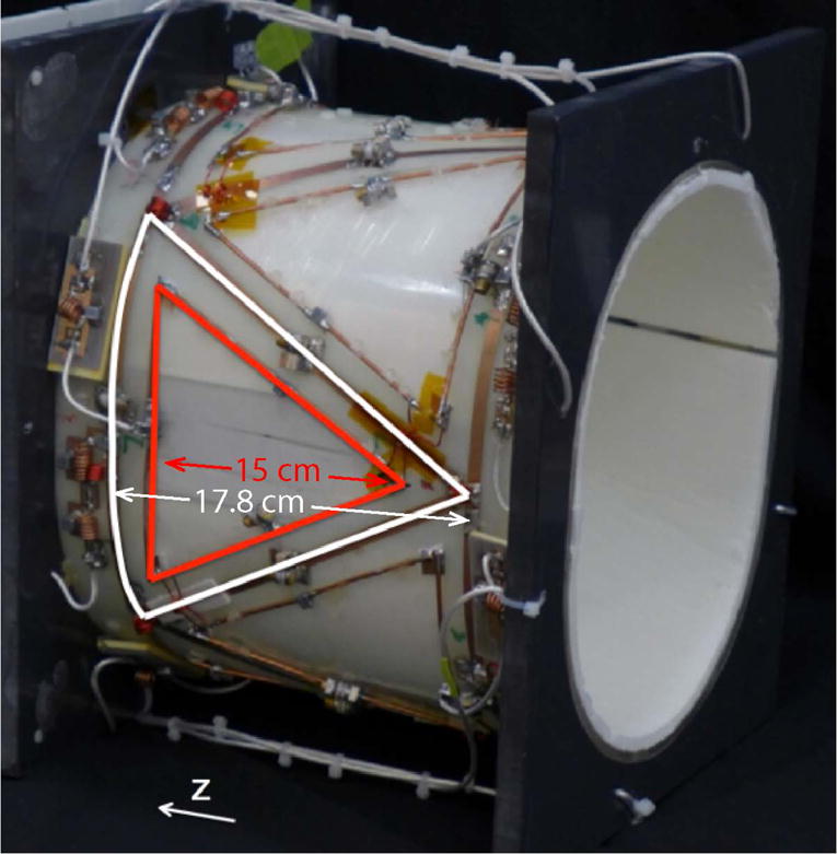
Photograph of the eight-channel sodium/proton coil array. One sodium and one proton element are highlighted in white and red, respectively.
The triangle array was interfaced to the scanner with a one-to-eight way power splitter. To achieve circularly polarized transmit excitation, home-built lumped element phase shift networks were added to provide 45° phase offsets according to the azimuthal location of the coil elements. Individual power splitter outputs were connected to Tx/Rx switches20 to protect the preamplifiers during sodium excitation (Figure 2a). Two cable traps tuned to the sodium and proton frequencies separated the coil ground from the common ground shared by the interface. Preamplifier decoupling was achieved by adding a phase shift network in the receive path that transformed the low input impedance of the preamplifier into an inductance that formed a parallel resonant circuit with the match capacitor21.
Figure 2.

Flattened two-dimensional schematic diagram (a) of the eight-channel sodium/proton coil array and interface. For simplicity, a single sodium (black) and proton coil (red) are highlighted, while neighboring elements are displayed in gray. Approximate capacitor values are: CM23Na = 390 pF, C123Na = 290 pF, C223Na = 216 pF, CM1H = 40 pF, C11H = 31 pF, and C21H = 12 pF. Decoupling inductors were hand wound using 20 AWG wire with 3 turns and 6.4 mm inner diameter for MNa, and 2 turns and 4.1 mm inner diameter for MH. Abbreviations: RFS = radiofrequency short (1000 pF) and RFC = radiofrequency choke (10 μH). The status of the DC bias is forward in transmission and reverse in receive mode. A detailed block diagram of the proton power divider is shown in (b).
A rational question regarding the triangle coil is how does its efficiency compare to a rectangular loop whose rungs are aligned with the z-axis. To answer this question, we performed full wave electromagnetic simulations using the finite difference time domain method in Computer Simulation Technology (CST) Studio Suite (Framingham, MA). One triangle (height = 17.8 cm and base = 17.8 cm) and one rectangle (8.9 cm L/R × 17.8 cm H/F) loop with the same area were simulated. The coils were loaded with a phantom with relative permittivity = 51 and conductivity = 0.44 S/m at 32.6 MHz. The coils were tuned, matched and excited with 50 Ω ports and the transmit fields were normalized to 1 W accepted power. Accepted power was defined as input power minus the reflected power from the coil element.
Proton Array
Our intention was to integrate an array of eight transmit/receive triangular proton elements with the sodium array to enable B0 shimming and standard proton MRI. RF simulations using the CST Studio Suite were performed to investigate the efficiency of the proton coils in the presence of the sodium coils and vice versa. A proton element was modeled as a triangular loop (15 cm base L/R and length = 15 cm H/F) that was tuned and matched to 123.2 MHz and 50 Ω in the presence of the simulated phantom described above. The proton loop was concentrically nested inside the sodium element whose dimensions are given above. The B1+ of the proton and sodium elements was recorded in isolation (while the counterpart was removed from the simulation) and in the presence of its nested counterpart.
In practice, the proton coils were constructed using 12 American wire gauge (AWG) copper wires to reduce eddy currents induced by neighboring coils22,23. The Q was approximately 180 (unloaded) and 50 (loaded). Each coil was tuned to 123.2 MHz using four distributed capacitors and matched to 50Ω in the presence of the tissue-equivalent head load. The neighboring proton elements were decoupled by linked counter-wound inductors (Figure 2a). Next-nearest neighbor decoupling was not necessary.
A proton interface was designed and constructed in house to facilitate transmit-receive operation. Transmission was driven through three stages of Wilkinson power dividers and quadrature hybrids24 arranged to provide outputs with 45° phase offsets that corresponded to the azimuthal location of the proton coil elements (Figure 2b). Individual power splitter outputs were connected to Tx/Rx switches to protect the preamplifiers during proton transmission. Preamplifier decoupling and common mode current reduction were achieved in an analogous manner to that described for the sodium array.
MRI Measurements
All imaging experiments were performed on Siemens 3 Tesla Trio scanner that was upgraded to Prisma during the course of this work (Siemens Healthineers, Germany). Human subjects were scanned after obtaining their informed written consent. Sodium and proton transmit power was restricted to 5 W/kg based on MR thermometry measurements similar to that described in Ref.25 to enforce a two-fold safety buffer below the 10 W/kg limit set by the International Electrotechnical Commission (IEC document 60601-2-33 2010). SNR and B1+ benchmark measurements were performed with the developed array and a third-party dual-nuclei sodium/proton head coil (Stark Contrast, Erlangen, Germany) available at our center. The benchmark coil was a dual tuned birdcage coil with 16 rungs, 30 cm length and 27 cm diameter. High impedance trap circuits were incorporated to achieve resonance at 32.6 and 123.2 MHz26,27. While its dimensions do not allow a strictly fair comparison to the developed coil, its familiar birdcage topology is expected to provide a good point of reference.
SNR maps were calculated from separate signal and noise (with the RF pulse amplitude set to zero) measurements acquired with a gradient echo pulse sequence and processed with the optimal array combination method28. The sodium/proton SNR acquisition parameters were as follows: TR = 200/500 ms, TE = 2.9/3.82 ms, flip angle = 90/10°, voxel size = 7.8 × 7.8 × 30/0.9 × 0.9 × 3 mm3, and acquisition time = 3 min 26 s/2 min 07s. The proton B1+ field was measured using the method described in Ref29. Because the pulse sequence was not available for non-proton nuclei, sodium B1+ maps were calculated by scaling the period of a sine curve to the pixel-wise signal intensities of a series of gradient echo sodium images that were collected with a range of imaging pulse amplitudes30.
Sodium imaging was demonstrated using a three-dimensional non-Cartesian Fermat looped orthogonally encoded trajectories (FLORET) acquisition31,32 with the following parameters: TR = 100 ms, TE = 0.2 ms, flip angle = 80°, resolution = 5 mm isotropic, acquisition time = 11 min 15 s. Proton anatomical imaging was performed with a magnetization-prepared rapid acquisition gradient echo (MPRAGE) sequence: TR = 2100 ms, TE = 2.52 ms, TI = 900 ms, flip angle = 8°, resolution = 1.6 mm isotropic, parallel acceleration factor = 2 (array)/1 (birdcage), and acquisition time = 3 min 09 s (array)/5 min 34 s (birdcage).
Results
The reflection curve (Figure 3) of a single element in the rectangular array shows significant coupling with the next-nearest neighbor that results in familiar resonant mode splitting. The match dropped from −15 dB in isolation to −4 dB in the presence of the next-nearest neighbor. The triangular element maintains a single resonance in the presence of its next nearest neighbor owing to the shared counter-wound inductors at the triangle vertices. Nearest-neighbor decoupling was preserved with shared rung capacitors.
Figure 3.

Reflection coefficient for one element of a three-channel rectangular array (left) shows a split resonance characteristic of strong coupling between next-nearest neighbor coils. Decoupling inductors in a triangular array remove next-nearest neighbor coupling and result in a single resonance (right).
Simulated sodium B1+ fields showed that the triangular loop efficiency was about 90% of the rectangular loop at a depth of 150 mm along the main axis. The primary explanation for this difference is greater z-directed magnetic fields are generated by the angled rungs of the triangular compared to rectangular element.
B1+ simulations show that a sodium loop is almost unaffected by the presence of the proton loop (Figure 4 top row). On the other hand, the proton loop is shielded by the sodium loop, which provides a minor improvement in transmit efficiency at the surface and reduction at depths greater than 98 mm along the main axis of the coil compared to an isolated proton element (Figure 4 bottom row).
Figure 4.

Simulated maps show the ratio of B1+ for a sodium (top row) or proton (bottom row) triangle coil with its nested multinuclear counterpart to that of the same coil in isolation. The sodium coil provides approximately identical B1+ in both the isolated and multinuclear environment. The presence of the sodium coil shields the proton coil, which increases efficiency near the surface but degrades efficiency at depths greater than approximately 9.8 cm.
The S-parameters for the eight-channel triangle array show that the lumped element decoupling provided −13.0 dB isolation between neighboring coils and −15.4 dB between next-nearest neighbors (Table 1). No mechanism was installed to counteract coupling between third and fourth-distant neighbors, which had an average value of −9.3 dB.
Table 1.
Scattering matrix measurements show coil match and isolation. The triangular elements enabled local lumped element decoupling between nearest and next-nearest neighbors. No mechanism was installed to counteract distant-neighbor coupling. Values indicate mean ± standard deviation (maximum value).
| S (dB) | |
|---|---|
| Sodium coils | |
| Diagonal elements | −15.8 ± 0.3 (−15.3) |
| Adjacent neighbors | −13.0 ± 0.4 (−12.4) |
| Next nearest neighbors | −15.4 ± 0.8 (−14.2) |
| Distant neighbors | −9.3 ± 0.2 (−8.8) |
|
| |
| Proton coils | |
| Diagonal elements | −21.7 ± 1.7 (−18.2) |
| Adjacent neighbors | −15.2 ± 1.1 (−13.3) |
| Next nearest neighbors | −13.2 ± 1.0 (−12.2) |
| Distant neighbors | −11.5 ± 1.0 (−10.6) |
The eight-channel sodium array provided 1.6-fold higher SNR in the center of the head and up to 2.3-fold gain in the periphery compared to the dual-tuned birdcage reference coil (Figure 5). FLORET images show good coverage and adequate sensitivity for 5 mm isotropic resolution.
Figure 5.

FLORET (Fermat looped orthogonally encoded trajectories) sodium images acquired with the eight-channel array show excellent coverage and delineation of brain structures (top row). The sodium signal-to-noise ratio (SNR) maps show that the eight-channel array (second row) provided a 1.6-fold gain in the head center and up to 2.3-fold gain in the periphery compared with the dual-nuclei birdcage (fifth row). The transmit field (B1+) was 62.7 ± 8.4 μT/√kW for the array and 59.5 ± 4.7 μT/√kW for the birdcage in the central transverse plane in the phantom.
The insertion loss of the sodium transmit module was −0.5 ± 0.2 dB with 45 ± 1° phase intervals at each output. B1+ maps acquired in the head phantom show that the array generated a transmit field of 62.7 ± 8.4 μT/√kW, while the dual tuned birdcage generated 59.5 ± 4.7 μT/√kW in the central transverse slice.
The proton transmit module had −0.6 ± 0.3 dB insertion loss at 45 ± 3° phase intervals at each output. The proton SNR at the center of the head was similar to that of the dual-tuned birdcage (Figure 6). As expected, the array provided significant SNR gains in the periphery but limited coverage in the H/F direction. B1+ maps acquired in vivo show that the array produced a transmit field of 14.6 ± 1.9 μT/√kW and the dual tuned birdcage produced a transmit field of 16.7 ± 2.0 μT/√kW in the central transverse plane with peripheral fat and skull regions removed. Example 1.6-mm isotropic MPRAGE images are shown in the top row of Figure 6.
Figure 6.

The exemplary proton MPRAGE images acquired with the eight-channel array show good T1 contrast in the central brain but falloff in the head apex (top row). Images were acquired with parallel acceleration factor = 2 (array) and 1 (birdcage). The array provided similar SNR in the center of the brain and gains in the periphery compared to the proton channel of the dual nuclei birdcage (second and fourth rows). The B1+ maps (third and bottom rows) show that the array provided a transmit field of 14.6 ± 1.9 μT/√kW, while the birdcage provided 16.7 ± 2.0 μT/√kW in the brain region (peripheral fat and skull excluded) in the transverse plane.
Discussion and Conclusions
We developed a modified degenerate mode birdcage using triangular elements. While a conventional degenerate mode birdcage has the potential for desirable excitation and reception properties, it is in practice difficult to achieve complete degeneracy due to coupling between non-adjacent neighbor elements33. Although coupling can be dampened by strong tissue loading in high frequency implementations34,35, we observed resonance frequency splitting at 32.6 MHz. By tilting the rungs away from the z-direction, the shared triangle vertices provided a means to decouple nearest and next-nearest neighbor coils using local lumped elements (Figure 3). This decoupling strategy allowed the modified degenerate mode birdcage to produce a uniform and circularly polarized B1+ field and provide the receive sensitivity gains associated with a multi-channel phased-array for sodium imaging (Figure 5). A secondary benefit is that it’s transmit/receive capability eliminated the need for lossy detuning circuitry that would be required in a ToRo array.
The choice of triangular sodium elements provided effective neighbor and next nearest neighbor decoupling, however there was no mechanism in place to counteract coupling between third and fourth-order neighbors, which had an average value of −9.3 dB (Table 1). The transmit field variations observed in the sodium B1+ maps can be attributed to the higher order coupling observed between sodium elements. Further optimization such as customized transmit power distribution to the individual elements may also improve B1+ uniformity.
Although our eight-channel array provided substantially improved SNR over the birdcage coil, its spatially varying B1− field (and to a lesser extent B1+) can make sodium quantification less straightforward. The phantom replacement method36,37, in which pre-scans are performed on a variety of phantoms in order to relate the spatially dependent signal intensity to sodium concentration, is a viable option for quantification.
We applied the triangle degenerate mode concept in an eight-channel array for sodium MRI of the brain. This application additionally called for proton MRI capability, which was pursued with proton elements that were inserted concentric to the sodium coils to reduce inter element coupling and overall design complexity. Though this design choice greatly reduced design complexity, it resulted in proton elements that were small in size with gaps between them. Gaps caused signal and B1+ nulls that were mainly confined to peripheral fat and skull, while the B1+ uniformity in a transverse slice through the brain was similar to that of the reference birdcage. Further, counter-rotating currents were induced in the nested dual-nuclei arrays that reduced proton coil efficiency. Possible approaches to reduce counter rotating currents are to switch to an interleaved coil arrangement where the proton array is offset with respect to the sodium array14,38 or to install proton filters in the sodium array, which can be expected to reduce sodium performance by about 5% on each element31,32.
In conclusion, we designed and implemented a multi-channel sodium/proton array for brain MRI at 3 T. The triangular geometry provided convenient shared locations for nearest and next-nearest neighbor decoupling, which allowed Tx/Rx operation as a modified degenerate birdcage mode array. The sodium module provided at least a 1.6-fold SNR gain over a dual-nuclei sodium birdcage coil, while proton channel performance was sufficient for anatomical imaging. The coil has helped overcome low-sodium MR sensitivity and improve quantification in neurological studies including epilepsy, traumatic brain injury and multiple sclerosis39,40.
Acknowledgments
A brief description of the coil was presented in part in, “An eight channel transmit receive sodium and nested eight channel transmit receive proton coil for 3.0 T brain imaging,” Proc: ISMRM, pp. 4879, 2014, Milan, Italy. Graham Wiggins and Ryan Brown disclosed the US patent, “Multi-Channel Coil Arrangement,” 13/866,728,2013, which is related to this work. The authors thank Cornel Stefanescu and Jerzy Walczyk for constructing the coil housing and Riccardo Lattanzi for the SNR calculation tool. This work was partially supported by NIH grants 1R03AR065763 and 1R01NS097494, and was performed under the rubric of the Center for Advanced Imaging Innovation and Research (CAI2R, www.cai2r.net) at the New York University School of Medicine, which is an NIBIB Biomedical Technology Resource Center (NIH P41 EB017183). The authors dedicate this manuscript to Dr. Graham Wiggins who passed away unexpectedly during its preparation. Dr. Wiggins was a great mentor and even better person. The MRI hardware community has lost a true pioneer in his passing.
Abbreviations used
- MRI
magnetic resonance imaging
- MS
multiple sclerosis
- UTE
ultrashort echo time
- RF
radio frequency
- ToRo
transmit-only/receive-only
- Tx/Rx
transcieve
- SNR
signal-to-noise ratio
- L/R
left - right
- H/F
head – feet
- A/P
Anterior-posetrior
- Tx
transmit
- IEC
International Electrotechnical Commission
- TE
echo time
- TR
repetition time
- FLORET
fermat looped orthogonally encoded trajectories acquisition
- TPI
twisted projection Imaging
- MPRAGE
magnetization-prepared rapid acquisition gradient echo
- FLAIR
fluid-attenuated inversion recovery
- RFC
Radio frequency choke
- RFS
Radio frequency short
References
- 1.Boada FE, LaVerde G, Jungreis C, Nemoto E, Tanase C, Hancu F. Loss of cell ion homeostasis and cell viability in the brain: What sodium MRI can tell us. Curr Top Dev Biol. 2005;70:77–+. doi: 10.1016/S0070-2153(05)70004-1. [DOI] [PubMed] [Google Scholar]
- 2.Ouwerkerk R. Sodium MRI. Methods in molecular biology. 2011;711:175–201. doi: 10.1007/978-1-61737-992-5_8. [DOI] [PubMed] [Google Scholar]
- 3.Madelin G, Lee JS, Regatte RR, Jerschow A. Sodium MRI: methods and applications. Progress in nuclear magnetic resonance spectroscopy. 2014 May;79:14–47. doi: 10.1016/j.pnmrs.2014.02.001. [DOI] [PMC free article] [PubMed] [Google Scholar]
- 4.Fleysher L, Oesingmann N, Brown R, Sodickson DK, Wiggins GC, Inglese M. Noninvasive quantification of intracellular sodium in human brain using ultrahigh-field MRI. NMR Biomed. 2013 Jan;26(1):9–19. doi: 10.1002/nbm.2813. [DOI] [PMC free article] [PubMed] [Google Scholar]
- 5.Thulborn K, Lui E, Guntin J, et al. Quantitative sodium MRI of the human brain at 9.4 T provides assessment of tissue sodium concentration and cell volume fraction during normal aging. NMR Biomed. 2016 Feb;29(2):137–143. doi: 10.1002/nbm.3312. [DOI] [PMC free article] [PubMed] [Google Scholar]
- 6.Mellon EA, Pilkinton DT, Clark CM, et al. Sodium MR imaging detection of mild Alzheimer disease: preliminary study. AJNR Am J Neuroradiol. 2009 May;30(5):978–984. doi: 10.3174/ajnr.A1495. [DOI] [PMC free article] [PubMed] [Google Scholar]
- 7.Biller A, Pflugmann I, Badde S, et al. Sodium MRI in Multiple Sclerosis is Compatible with Intracellular Sodium Accumulation and Inflammation-Induced Hyper-Cellularity of Acute Brain Lesions. Sci Rep. 2016 Aug 10;6:31269. doi: 10.1038/srep31269. [DOI] [PMC free article] [PubMed] [Google Scholar]
- 8.Thulborn KR, Lu A, Atkinson IC, Damen F, Villano JL. Quantitative sodium MR imaging and sodium bioscales for the management of brain tumors. Neuroimaging clinics of North America. 2009 Nov;19(4):615–624. doi: 10.1016/j.nic.2009.09.001. [DOI] [PMC free article] [PubMed] [Google Scholar]
- 9.Boada FE, Gillen JS, Shen GX, Chang SY, Thulborn KR. Fast three dimensional sodium imaging. Magn Reson Med. 1997 May;37(5):706–715. doi: 10.1002/mrm.1910370512. [DOI] [PubMed] [Google Scholar]
- 10.Brown R, Khegai O, Parasoglou P. Magnetic Resonance Imaging of Phosphocreatine and Determination of BOLD Kinetics in Lower Extremity Muscles using a Dual-Frequency Coil Array. Sci Rep. 2016;6:30568. doi: 10.1038/srep30568. [DOI] [PMC free article] [PubMed] [Google Scholar]
- 11.Brown R, Lakshmanan K, Madelin G, et al. A flexible nested sodium and proton coil array with wideband matching for knee cartilage MRI at 3T. Magn Reson Med. 2015 Oct 26; doi: 10.1002/mrm.26017. [DOI] [PMC free article] [PubMed] [Google Scholar]
- 12.Brown R, Madelin G, Lattanzi R, et al. Design of a nested eight-channel sodium and four-channel proton coil for 7T knee imaging. Magn Reson Med. 2013 Jul;70(1):259–268. doi: 10.1002/mrm.24432. [DOI] [PMC free article] [PubMed] [Google Scholar]
- 13.Moon CH, Kim JH, Zhao T, Bae KT. Quantitative (23) Na MRI of human knee cartilage using dual-tuned (1) H/(23) Na transceiver array radiofrequency coil at 7 tesla. J Magn Reson Imaging. 2013 Nov;38(5):1063–1072. doi: 10.1002/jmri.24030. [DOI] [PubMed] [Google Scholar]
- 14.Kaggie JD, Hadley JR, Badal J, et al. A 3 T sodium and proton composite array breast coil. Magn Reson Med. 2014 Jun;71(6):2231–2242. doi: 10.1002/mrm.24860. [DOI] [PMC free article] [PubMed] [Google Scholar]
- 15.Shajan G, Mirkes C, Buckenmaier K, Hoffmann J, Pohmann R, Scheffler K. Three-layered radio frequency coil arrangement for sodium MRI of the human brain at 9.4 Tesla. Magn Reson Med. 2016 Feb;75(2):906–916. doi: 10.1002/mrm.25666. [DOI] [PubMed] [Google Scholar]
- 16.Avdievich NI, Hetherington HP. 4T Actively detuneable double-tuned 1H/31P head volume coil and four-channel 31P phased array for human brain spectroscopy. Journal of Magnetic Resonance. 2007;186(2):341–346. doi: 10.1016/j.jmr.2007.03.001. 2007/06/01/ [DOI] [PMC free article] [PubMed] [Google Scholar]
- 17.Lin F, Kwong K, Huang I, Belliveau J, Wald L. Degenerate mode birdcage volume coil for sensitivity-encoded imaging. Magn Reson Med. 2003;50:1107–1111. doi: 10.1002/mrm.10632. [DOI] [PubMed] [Google Scholar]
- 18.Wiggins GC, Zhang B, Chen G, Sodickson D. ISMRM. Melbourne, Australia: 2012. A Highly Decoupled 8 Channel Transmit-Receive Loop Array for 7T with Diverse B1 Profiles. [Google Scholar]
- 19.Duan Q, Duyn JH, Gudino N, et al. ISMRM. Milan, Italy: 2014. Characterization of a Dielectric Phantom for High-Field MRI Applications. [DOI] [PMC free article] [PubMed] [Google Scholar]
- 20.Shajan G, Hoffmann J, Budde J, Adriany G, Ugurbil K, Pohmann R. Design and evaluation of an RF front-end for 9.4 T human MRI. Magn Reson Med. 2011 Aug;66(2):596–604. doi: 10.1002/mrm.22808. [DOI] [PubMed] [Google Scholar]
- 21.Roemer PB, Edelstein WA, Hayes CE, Souza SP, Mueller OM. The NMR phased array. Magn Reson Med. 1990 Nov;16(2):192–225. doi: 10.1002/mrm.1910160203. [DOI] [PubMed] [Google Scholar]
- 22.Wiggins GC, Polimeni JR, Potthast A, Schmitt M, Alagappan V, Wald LL. 96-Channel receive-only head coil for 3 Tesla: design optimization and evaluation. Magn Reson Med. 2009 Sep;62(3):754–762. doi: 10.1002/mrm.22028. [DOI] [PMC free article] [PubMed] [Google Scholar]
- 23.Kumar A, Edelstein WA, Bottomley PA. Noise figure limits for circular loop MR coils. Magn Reson Med. 2009 May;61(5):1201–1209. doi: 10.1002/mrm.21948. [DOI] [PMC free article] [PubMed] [Google Scholar]
- 24.Pozar DM. Microwave Engineering. 3. New York: Wiley; 2005. [Google Scholar]
- 25.Brown R, Deniz CM, Zhang B, Chang G, Sodickson DK, Wiggins GC. Design and application of combined 8-channel transmit and 10-channel receive arrays and radiofrequency shimming for 7-T shoulder magnetic resonance imaging. Invest Radiol. 2014 Jan;49(1):35–47. doi: 10.1097/RLI.0b013e3182a5662d. [DOI] [PMC free article] [PubMed] [Google Scholar]
- 26.Shen GX, Boada FE, Thulborn KR. Dual-frequency, dual-quadrature, birdcage RF coil design with identical B1 pattern for sodium and proton imaging of the human brain at 1.5 T. Magn Reson Med. 1997 Nov;38(5):717–725. doi: 10.1002/mrm.1910380507. [DOI] [PubMed] [Google Scholar]
- 27.Schnall MD, Subramanian VH, Leigh JS, Chance B. A new double-tuned probe for concurrent 1H and 31P NMR. J Magn Reson. 1985;65:122–129. [Google Scholar]
- 28.Kellman P, McVeigh ER. Image reconstruction in SNR units: a general method for SNR measurement. Magn Reson Med. 2005 Dec;54(6):1439–1447. doi: 10.1002/mrm.20713. [DOI] [PMC free article] [PubMed] [Google Scholar]
- 29.Fautz HP, Vogel M, Gross P, Kerr A, Zhu Y. ISMRM. Toronto, Ontario: 2008. B1 mapping of coil arrays for parallel transmission. [Google Scholar]
- 30.Hornak JP, Szumowski J, Bryant RG. Magnetic field mapping. Magnetic Resonance in Medicine. 1988;6(2):158–163. doi: 10.1002/mrm.1910060204. [DOI] [PubMed] [Google Scholar]
- 31.Pipe JG, Zwart NR, Aboussouan EA, Robison RK, Devaraj A, Johnson KO. A new design and rationale for 3D orthogonally oversampled k-space trajectories. Magn Reson Med. 2011 Nov;66(5):1303–1311. doi: 10.1002/mrm.22918. [DOI] [PubMed] [Google Scholar]
- 32.Madelin G, Kline R, Walvick R, Regatte RR. A method for estimating intracellular sodium concentration and extracellular volume fraction in brain in vivo using sodium magnetic resonance imaging. Sci Rep. 2014;4:4763. doi: 10.1038/srep04763. [DOI] [PMC free article] [PubMed] [Google Scholar]
- 33.Cheng Y-CN, Eagan TP, Chmielewski T, et al. A degeneracy study in the circulant and bordered-circulant approach to birdcage and planar coils. Magnetic Resonance Materials in Physics, Biology and Medicine. 2003 Jul 01;16(2):103–111. doi: 10.1007/s10334-003-0009-5. [DOI] [PubMed] [Google Scholar]
- 34.Brown R, Lakshmanan K, Madelin G, Parasoglou P. A nested phosphorus and proton coil array for brain magnetic resonance imaging and spectroscopy. Neuroimage. 2016 Jan 1;124(Pt A):602–611. doi: 10.1016/j.neuroimage.2015.08.066. [DOI] [PMC free article] [PubMed] [Google Scholar]
- 35.Alagappan V, Nistler J, Adalsteinsson E, et al. Degenerate mode band-pass birdcage coil for accelerated parallel excitation. Magn Reson Med. 2007 Jun;57(6):1148–1158. doi: 10.1002/mrm.21247. [DOI] [PubMed] [Google Scholar]
- 36.Atkinson IC, Lu A, Thulborn KR. Clinically constrained optimization of flexTPI acquisition parameters for the tissue sodium concentration bioscale. Magn Reson Med. 2011 Oct;66(4):1089–1099. doi: 10.1002/mrm.22908. [DOI] [PMC free article] [PubMed] [Google Scholar]
- 37.Jansen JF, Backes WH, Nicolay K, Kooi ME. 1H MR spectroscopy of the brain: absolute quantification of metabolites. Radiology. 2006 Aug;240(2):318–332. doi: 10.1148/radiol.2402050314. [DOI] [PubMed] [Google Scholar]
- 38.Brown R, Khegai O, Parasoglou P. Magnetic Resonance Imaging of Phosphocreatine and Determination of BOLD Kinetics in Lower Extremity Muscles using a Dual-Frequency Coil Array. 2016;6:30568. doi: 10.1038/srep30568. 07/28/online. [DOI] [PMC free article] [PubMed] [Google Scholar]
- 39.Shepherd T, Qian Y, Lakshmanan K, Kuzniecky R, Wiggins G, Boada FE. ISMRM. Toronto, ON, CA: 2016. Sodium MRI for Evaluation of Sodium Ion Homeostasis in Epilepsy: Clinical Implementation and Initial Impressions. [Google Scholar]
- 40.Lui Y, Qian Y, Lakshmanan K, et al. ISMRM. Toronto, ON, CA: 2016. Distribution of brain sodium after mild traumatic brain injury. [Google Scholar]