Abstract
Functionalized membranes containing nanoparticles provide a novel platform for organic pollutant degradation reactions and for selective removal of contaminants without the drawback of potential nanoparticle loss to the environment. These eco-friendly and sustainable technology approaches allow various water treatment applications through enhanced water transport through the membrane pores. This paper presents “green” techniques to create nanocomposite materials based on sponge-like membranes for water remediation applications involving chlorinated organic compounds. First, hydrophobic hollow fiber microfiltration membranes (HF) of polyvinylidene fluoride were hydrophilized using a water-based green chemistry process with polyvinylpyrrolidone and persulfate. HF and flat sheet membrane pores were then functionalized with poly(acrylic acid) and synthesized Fe/Pd nanoparticles. Surface modifications were determined by contact angle, surface free energy and infrared spectroscopy. The synthesized nanoparticles were characterized by electronic microscopy, X-ray spectrometry and image analysis. Nanoparticle sizes of 193 and 301 nm were obtained for each of the membranes. Depending on the concentration of the dopant (Pd) in the membrane, catalytic activity (established by trichloroethylene (TCE) reduction), was enhanced up to tenfold compared to other reported results. Chloride produced in reduction was close to the stoichiometric 3/1 (Cl−/TCE), indicating complete absence of reaction intermediates.
Keywords: Sponge-like membranes, surface modification, nanoparticles, TCE dechlorination
Graphical Abstract
INTRODUCTION
Clean water accessibility is a serious concern in all aspects of society, generating social, economic and environmental problems. Obtaining purified water for drinking or industrial purposes is becoming an enormous challenge.1 Membranes are finding wide applications in various areas ranging from water to energy applications to food and bioprocessing. Traditional membranes are based on size exclusion, charge repulsions, or sorption/diffusion aspects. On the other hand, biological membranes have diverse functional groups and provide high selectivity. One can obtain advance synthetic microfiltration membranes through pore functionalization (using water-based green chemistry) approaches and by creating reactive sites for toxic organic degradation through metal nanoparticle incorporation.
Within a range of materials, polyvinylidene fluoride (PVDF) membranes are being used extensively in many applications because of their excellent thermal stability, chemical and mechanical properties. PVDF however, is hydrophobic with a low surface free energy resulting in poor wettability,2 producing organic fouling in aqueous solution applications.3 Hence, hydrophilization of PVDF is a challenging subject in water purification processes.
Functionalization of PVDF membranes for water purification is an extensive field of study.4 Most studies of functionalization have been done in flat sheet membranes for water detoxification, including: sustainable green synthesis of metallic nanoparticles (NPs) with good effectiveness and low toxicity;5 enzyme incorporation by layer-by-layer deposition;6 pH and temperature responsive applications.7 Many of these functionalization processes are carried out by the cross-linking of polymers (hydrogels) on top of the porous structure of the membrane, without affecting the physicochemical properties of the material, which happens with other methods.8
Although sponge-like membranes are also used in water purification applications such as membrane bioreactors, most of them are used in membrane distillation and membrane contactors for gas-liquid and liquid-liquid separations;9 these membranes have higher surface area and more accessibility than the flat sheet membranes commonly used in water applications. However, most sponge-like membrane functionalization has done on different membranes than the ones made of PVDF and there are relatively few studies describing functionalization on this material.10 Among these membranes is the hollow fiber (HF) type. These membranes do not have any supporting material like commercial flat sheet (FS) membranes. Most HF membranes are hydrophobic due to their fabrication by thermal induced phase separation (TIPS). Hollow fiber shows good mechanical strength and porous performance due to their thickness and high surface area, among other properties.11 Sponge-like flat sheet membranes have support material or can be self-supported; they are produced by non-solvent induced phase separation (NIPS) and can be hydrophobic or hydrophilic by modifying the solvent/non-solvent conditions of their fabrication.
To increase the hydrophilicity of PVDF, numerous scientific studies have been made, from blending to surface modification.12 In the casting modification, hydrophilic materials such as polyethylene glycol (PEG),11b poly(methyl methacrylate) (PMMA)13 or polyvinylpyrrolidone (PVP) have been incorporated.9c Surface modification can be made by cross-linking poly(vinyl alcohol) (PVA)14 or PVP;15 by covalent bonding hydrophilic moieties following alkaline pretreatment16 or even grafting them onto the polymer chain.17
The present article discusses three aspects as follows: (1) the in-lab fabrication and characterization of a PVDF hydrophobic HF membrane; (2) the HF hydrophilization, by cross-linking of PVP on the surface, and the subsequent evaluation of the membrane fabricated; (3) the functionalization of PVDF membranes, HF and FS, by polymerizing a hydrogel of poly(acrylic acid) (PAA). (4) The Fe NPs synthesis and post-coating with Pd along with NP size characterization and description by diverse physical chemistry methods and image analysis and (5), the evaluation of the membrane catalytic activity in dechlorination reactions using trichloroethylene (TCE) as model compound.
TCE was selected because its low concentration in water demands costly ex situ treatments, without destroying it in most cases. Shifting to an in situ treatment offers lower costs and iron nanoparticles have thoroughly demonstrated their capability of reductive dechlorination in this field.18 TCE is a pollutant that has low biodegradability, making it very persistent in nature, is heavier than water and small quantities of it go onto the soil and ground water, contaminating them. TCE then, is released very slowly with a half-life between months and decades. Due to these reasons, its treatment and elimination is necessary.
EXPERIMENTAL
Materials
Acrylic acid (AA, 99%), potassium tetrachloropalladate (II) (K2PdCl4, 98%), sodium borohydride (NaBH4, 99.99%), 1, 2 dibromoethane (EDB, 99+ %) (Sigma-Aldrich, St. Louis, MO, USA), ammonium persulfate (APS, (NH4)2S2O8), dibutyl phthalate (DBP) (EM Science for Merck KGaA, Darmstadt, Germany). Ferrous chloride tetrahydrate (FeCl2·4H2O), trichloroethylene (TCE = 99.9+ %), sodium hydroxide (NaOH) solution, sodium chloride (NaCl), sulfuric acid (H2SO4) solution and nitric acid, pentane (Fisher Scientific, Fair Lawn, NJ, USA). Polyvinylidene fluoride polymer (PVDF) (Solef® 1015, MW = 516,000) (Solvay, France); polyvinylpyrrolidone (PVP) (MW=40,000) (Polysciences Inc., Warrington, PA, USA); Isopropanol (IPA, 99.9%), N, N′-methylenebisacrylamide (MBA > 99%) (Acros, New Jersey, NJ, USA). XPVDFSCO flat sheet microfiltration membranes (FS) with 0.40 μm pore size and 200 μm thickness (125 μm PVDF and 75 μm backing) (Nanostone, Oceanside, CA, USA). In all cases, HF and FS surface areas were based on the outer surface (10.9 cm2 on average) and the top surface area (17.3 cm2), respectively. All chemicals were of reagent grade and used as received.
Hollow Fiber Fabrication and Hydrophilization
One of the main approaches for preparation of PVDF microporous membranes is TIPS. The homogeneous solution was formed by dissolving 30 wt. percentage PVDF polymer in DBP at 170 ºC. The polymer solution and DBP as inner coagulant were pumped into a spinneret by gear pump and syringe pump, respectively. The phase separation of homogeneous solution was induced by cooling down the exiting HF membranes in a 5 cm air gap followed by quenching in a water bath at 10 ºC. After the solidification of polymer-rich phase, the morphology of porous membrane structure can be created by extraction, evaporation or freeze-drying.
The pore size and pore size distribution were measured by a capillary flow porometer (CFP) (Porous Materials, Inc. (PMI) CFP 1500A). The membrane samples were stabilized in the sample holder and wetted by a low surface tension liquid (Galwick). Then, nitrogen gas was allowed to pass through the saturated sample until the applied pressure exceeded the capillary attraction of the liquid in the membrane pores.
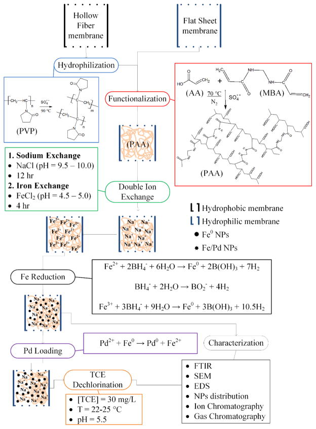
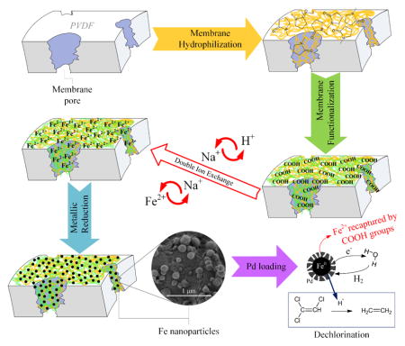
The hydrophilization and functionalization procedures made to the membranes are depicted in Scheme 1. As explained, HF membranes were fabricated without any addition of a hydrophilizing material. For this reason, the HFs had to be modified with PVP in order to use them in aqueous phase. HFs were treated in this study based on the results found elsewhere.15 Briefly, the membranes were washed with IPA for 2 h, then washed with deionized ultra-filtered water (DIUF) several times and finally put in an aqueous solution containing PVP (5 wt.%) and APS (0.4 wt.%) at 90 °C for 6 h with constant stirring.
Scheme 1.
Hydrophilization and functionalization of PVDF hollow fiber and flat sheet membranes. Reactions adapted from different authors.18a, 20–21, 42a, 42c
Membrane Functionalization
The membrane functionalization is made by free radical polymerization of the AA in the PVDF porous surface by dipping both membranes, HF and FS, in the monomer solution:19 AA (10 wt.% aqueous solution) with MBA as cross-linker (1.0 mol % of AA) and APS (1.0 mol % of AA) at 70 °C for 1 h in a N2 atmosphere. The next step is a double ion exchange, using NaCl in alkaline solution (1 g/L of Na; pH ≈ 10.5; T = 22 °C) and subsequently FeCl2·4H2O (200 mg/L of Fe; pH ≈ 4.6; T = 22 °C). After each procedure of hydrophilization and functionalization, the membranes were washed several times with DIUF water, dried and weighed. To check the membrane mass gain, the mass gain Δm (g/m2) was calculated: Δm = (w2 – w1)/A, were w1 and w2 are the weight (g) of the non-functionalized PVDF and the hydrophilized/functionalized membranes, respectively; and A is the outer (HF) or top (FS) surface areas (m2) of the membranes.
The hydrophilization of HF was determined from contact angle (CA) measurements, surface free energy calculations and infrared spectroscopy (IR). CA was measured using a NRL C. A. Goniometer (ramé-hart 100-00 115) at 20 ± 1 °C. The average CA was calculated from measurements on three sites of the surface, measuring the advancing and receding water CAs on both sides of the drop. The CA of the PVDF membrane varies depending on the solvents, chemical additives, manufacturing processes and conditions and other variables used in their fabrication. To verify the adhesion of PVP and PAA to the surface of the membranes, attenuated total reflectance Fourier transform infrared spectroscopy (ATR-FTIR) (Varian 7000e) was employed to validate qualitatively the presence of the chemical functional groups in each procedure. The spectrum was set between 500 and 4000 cm−1. Membrane samples were vacuum-dried and put onto a flat surface with tape before any analysis.
Nanoparticle Synthesis
After the ion exchange with FeCl2·4H2O, the membranes were put in a solution of sodium borohydride (2.5:1 molar of NaBH4 to Fe) to reduce the iron from Fe2+ to Fe0, making NPs (Scheme 1).20 Depending on pH and temperature conditions, Fe2+ oxidizes to Fe3+ and be reduced by NaBH4 which simultaneously can react with water producing hydrogen gas.18a, 20a, 21 By the same procedure, Fe NPs were synthesized in solution without membrane support in order to compare results. NPs in membranes and solution phase were analyzed by dynamic light scattering (DLS) (Malvern Instruments Zetasizer Nano-ZS90) after being strongly sonicated for two minutes (Fisher Scientific Sonic Dismembrator 100).
The membrane-NPs system was characterized with a focus ion beam (FIB) (Helios NanoLab 660) coupled with a scanning electron microscope (SEM) and energy dispersive X-ray spectrometer (EDS) detector (courtesy of FEI corp.) and with a SEM (Hitachi S-4300) operated between 3 and 20 kV of accelerating voltage. Samples were vacuum-freeze-dried in a LABCONCO FreeZone 2.5 Plus. Functionalized and control membrane samples were also analyzed with an EDS Zeiss EVO MA 10 with SE/VPSE (environmental)/BSE/EDX detectors to measure the elemental composition on the surface and cross-section of the membranes. Membrane samples were put in 20 mL EPA glass vials with DIUF water and sonicated at high output power (21 W) to determine NPs losses. Particle size analysis and statistics were performed using Malvern, Image J and SAS software packages.
To increase the TCE dechlorination performance,5a post-coating with palladium is applied using K2PdCl4 to form bimetallic Fe/Pd NPs. Palladium is used to create a layer on the iron that increases the reactivity and reach a complete dechlorination of the model pollutant, avoiding intermediate products. Sodium, iron and palladium ions from the ion exchange processes and nanoparticle synthesis were determined in an inductively coupled plasma optical emission spectrometer (ICP-OES) (Varian Vista-PRO ICP-OES) after digesting the membranes with a 20% nitric acid solution in 20 mL EPA glass vials overnight (300 rpm shaking).
Dechlorination Using Fe/Pd Nanoparticles
To establish the NPs reactivity within HF and FS membranes, dechlorinations of TCE were done in batch reaction experiments using 20 mL EPA glass vials in a shaker at 300 rpm. The functionalized membranes were immersed in 30 mg/L TCE stock solution during different periods of time (24 mL with no headspace per vial and time-lapse). The reaction was stopped by removal of the membranes. The membrane and aliquots of the solution were taken to extract the TCE with equal volume of pentane, containing EDB as internal standard, for 2 h. The extract was analyzed by gas chromatography – mass spectrometry (GC-MS) in a Hewlett-Packard 5890 Series II with a Hewlett-Packard 5971A detector. Aliquots were also analyzed for chloride concentration by ion chromatography with a conductivity detector (IC) (Dionex ICS 2500).
RESULTS AND DISCUSSION
Hollow Fiber and Flat Sheet Characterization
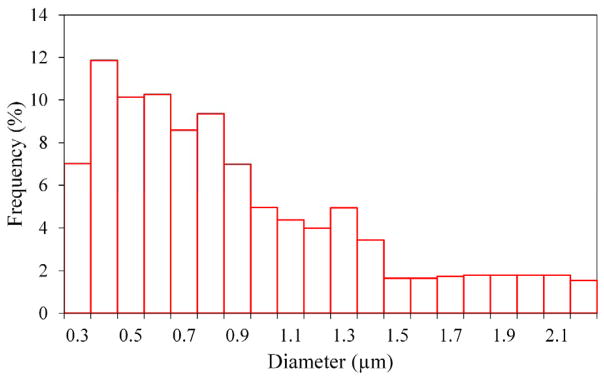
Non-functionalized PVDF membranes were analyzed by SEM images, capillary flow and gravimetric methods in order to describe and compare their characteristics and to determine their physical properties, such as pore size, thickness and structure, among others. The PVDF hollow fiber membrane fabricated, called T6-B, has 1.18 mm of outer diameter and 225 μm of thickness. Membrane porosity, εm, and pore size distribution were determined comparing the gas flow rates of wet and dry sample at the same pressures. The HF membrane pore sizes obtained by CFP are 0.72 μm for the median, the average pore size is 0.89 μm and the maximum is 2.2 μm. In Figure 1, the pore size distribution shows that more than half of the pores are less than or equal to 0.8 μm (57.2%). The membrane porosity, εm, is defined as the volume of the pores divided by the total volume of the membrane. It was determined by gravimetric method, measuring the weight of IPA (here as wetting solvent) contained in the membrane pores:
| (1) |
where ω1 is the weight of the wet membrane, ω2 is the weight of the dry membrane, ρI is the IPA density and ρP is the polymer density. Results for the T6-B membrane show a porosity of 59.6 ± 1.3 %.
Figure 1.
Pore size distribution of T6-B hollow fiber membrane.
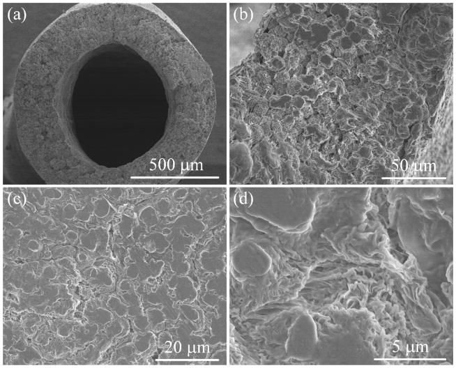
In Figure 2a-b, the HF membrane shows a thickness of about 250 μm, which is close to the value reported in its fabrication. The sponge-like morphology of cross-section in Figure 2b looks wrinkled, asymmetric and very porous. The outer surface showed in Figure 2c–d is porous structure with cracks sandwiched by crystalline sections (nonporous). Pores shown in Figure 2d are asymmetric with an apparent pore size close to that obtained by CFP. The unique pore structure is originated from the polymer lean phase surrounded by the crystallizing polymer-rich phase during the TIPS process.
Figure 2.
SEM images of PVDF hollow fiber membranes at different magnitudes. (a) Cross-section, (b) zoom-in of cross-section, (c) outer surface, (d) outer surface zoom-in.
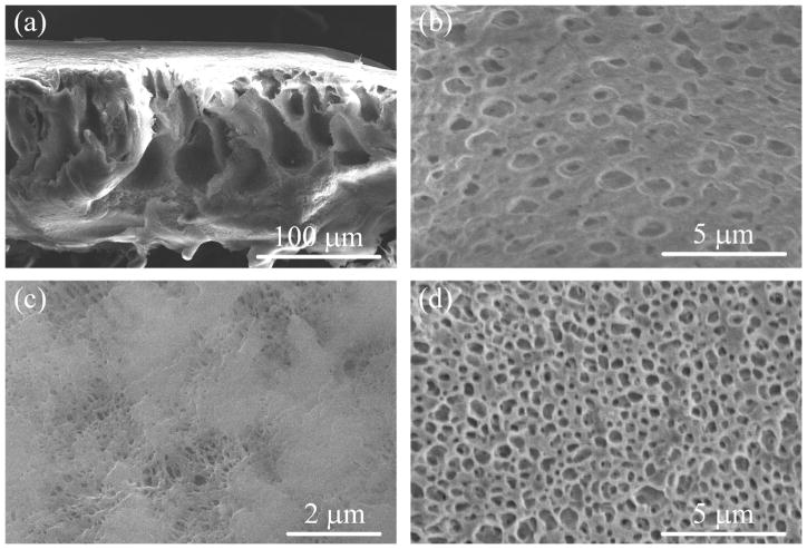
In the case of the non-functionalized FS (flat sheet membranes), the thickness reported by Nanostone is 125 μm, to which the experimental value is very close (Figure 3a). In these SEM images, Figure 3a–b and Figure 3d, it is possible to see the very porous, sponge-like and also macro-void structure of the FS membrane, unlike the HF, which only has a sponge-like structure. The top surface has different pore shapes and sizes with an upper limit of around 400 nm (Figure 3c). The bottom surface in Figure 3d (without the backing material), was found to possess a very porous structure (around 500 nm pore size).
Figure 3.
SEM images of PVDF flat sheet membranes at different magnitudes. (a) Cross-section, (b) zoom-in of cross-section, (c) top surface, (d) bottom surface without backing.
Contact Angle and Surface Free Energy Calculations
The surface free energy γSTOT was evaluated from the contact angle hysteresis22 of water on the HF membrane surfaces in each step of the hydrophilization, including the functionalization with PAA, using the equation:
| (2) |
Were γL is the surface tension of water at the temperature of the CA measurements; θA and θR are the advancing CA and the receding CA, respectively. The CA measurements and the evaluation of γSTOT are listed in Table 1 in each step of the treatment.
Table 1.
Contact angle and Surface Free Energy for HF membranes of at different steps of hydrophilization. Reference values are from pure or coated materials.
| Treatment Steps of the HF | Advancing Contact Angle θA (°) | Receding Contact Angle θR (°) | Surface free energy* γSTOT(mJ/m2) | Ref. Static Contact Angle θ (°) | Reference γSTOT (mJ/m2) |
|---|---|---|---|---|---|
| Hydrophobic HF Membrane | 76.3 ± 0.7 | 58.3 ± 1.2 | 40.26 | 72.5 (23a) | 33.2 (46) |
| Hydrophilization with PVP | 60.3 ± 1.2 | 39.7 ± 1.3 | 49.79 | 50.0 – 60.0 (47) | 43.4 (48) |
| Functionalization with PAA | 57.3 ± 2.0 | 30.3 ± 0.9 | 50.68 | 45.8 (49) | No data |
Calculated surface free energy value for water: γL = 72.7 mJ/m2 at 20°C.50
Membranes of PVDF can have CAs from around 75° (phase inversion with water) to 148° (phase inversion with alcohol) for hydrophobic applications.23 The hydrophilization of PVDF membranes using PVP is well established in industry and academia as a part of the casting process. However, hydrophilization as post-process has been implemented in few research studies and they have been presented as a cross-linking procedure discussed by different authors. Diverse methods have been explained, such as ring-opening and self-cross-linking by ethanol-acetone,24 ring-opening using sodium hypochlorite in alkaline solution,25 ether bonds with UV light26 or UV-H2O2 photo-initiation.27 The use of PVP using APS have also been discussed15, 28 stating that the persulfate ion generates a free radical reaction on the carbon-carbon main chain to induce the cross-linking within the PVP molecules.29 After the HF membranes were incorporated with PVP and PAA layers, the CA decreases and surface free energy increases simultaneously, as shown in Table 1. In this table, the calculated surface free energies are slightly higher than the references due to the porous outer surface of the membranes and the flattening caused in order to make the measurement.
Characterization of Functionalized Membranes
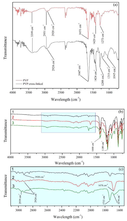
Infrared spectroscopy was used to characterize the hydrophilization and the functionalization of the membranes with PVP and PAA, respectively. First, the PVP cross-linking was established alone, since the concentrations used on the membranes were too low to describe the process by ATR-FTIR. On the Figure 4a, ATR-FTIR spectra show the PVP powder before and after the treatment with APS (PVP cross-linked). The empirical transmittance bands for the PVP are consistent with those previously reported in literature.30
Figure 4.
(a) ATR-FTIR spectra of PVP before and after treatment (PVP cross-linked) with APS on HF membranes. (b) ATR-FTIR spectra of (1) hydrophobic HF membranes, (2) HF membranes after PVP hydrophilization and (3) HF membranes after hydrophilization and subsequent functionalization with PAA. (c) Zoom-in of spectra showing the absorption bands of the PVP and PAA components.
The two characteristic peaks at 2361 and 2338 cm−1 are distinctive of the PVP spectrum. A broad peak (3399 cm-1) shows the higher presence of overlapping O-H and N-H groups in the hydrophilization process. The presence of free and numerous hydroxyl groups plus hydrogen bonds from residual water enhanced this band. There are also shifts in the symmetric CH2 stretches (2920 to 2924 cm−1), the carbonyl group stretches (C=O) (1651 to 1647 cm−1), the amine group stretches (C-N) (1420 to 1424 cm−1) and the CH bends (1273 to 1288 cm−1). This behavior is characteristic to water absorption.31 It is worth noting the addition of C-O stretches corresponding to ether group at 1045 and 1215 cm−1. This implies that the persulfate not only initiates a free radical cross-linking of PVP, but could also intervene in the ring-opening and etherification of the molecules.
In the Figure 4b–c the polymer functionalization on the membrane surface is shown. The presence of little transmittance bands is because of small amounts of material applied to the membranes, as explained before. The average mass gain for PVP (Δm = 5.20 g/m2) is slightly higher than the reported.15 For PAA, Δm = 5.04 g/m2. Both Δm can contribute to the obstruction of the pores. All spectra show the characteristic peaks of the C-F and C-F2 bonds in the range of 1100 and 1500 cm−1 (Figure 4b) without shifting, proving the chemical and thermal stability of the PVDF under these processes. The PVDF spectra before and after functionalization shows an addition at 1678 cm−1 from the ionized carbonyl group from the PAA polymerization. After the functionalization with PAA, the carbonyl band is shifted to 1674 cm−1 and a non-ionized band at 1732 cm−1 appears due to water absorption too. There are also shifting and small increases in the symmetric and asymmetric CH2 bands (2924 and 2959 cm−1) due to the extra chains from the PVP and PAA polymers.
Characterization of Nanoparticles in Membranes
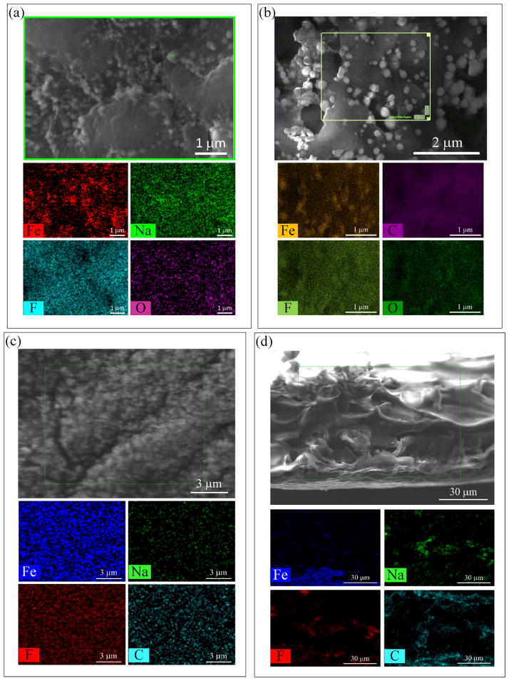
A comparison between the PVDF membranes before and after functionalization with PAA and subsequent Fe NPs in situ synthesis shows that the open structure of the HF membrane between the polymer blocks as well as the porous surface of the FS membrane are diminished (see Figure 5a and Figure 5c). Some aggregation of Fe NPs can be seen on the surface of the HF, but fewer aggregate on the FS membrane, which shows a more separated and uniform distribution as is confirmed by the EDS mapping. Sodium presence is due to the reduction of iron by NaBH4. Oxygen, fluorine and carbon served as reference compounds for the PVDF-PAA membrane.
Figure 5.
SEM-EDS imaging and mapping of PVDF-PAA-Fe hollow fiber and flat sheet membranes. (a) HF outer surface, (b) FIB cut of HF cross-section, (c) FS top surface, (d) FS cross-section.
In contrast, the internal structure of the membranes shows no changes (Figure 5b and Figure 5d). The densities of iron and sodium decrease with less agglomeration of Fe NPs. One explanation for this result is that due to the increase in the pH at the time of the iron reduction by NaBH4, the pores of the membrane were closed and the transport of solvents through the membrane was low, preventing the aggregation of NPs due to more spaced carboxyl groups. In the case of FS membranes, it illustrates that the polymerization was done mostly on the surface, then the pores of the membrane were blocked, and the transport of solvents through the membrane was low, preventing the production of more Fe NPs. The average results of iron loading, as Δm, from the ICP-OES are 1.65 and 4.80 g/m2 for HF and FS membranes, respectively. After sonication in DIUF water, the membranes show almost no iron losses. The DLS results showed a sample too polydisperse for cumulant analysis, also the value of Δm for HF was lower than 0.007 g/m2 and for FS was 0.05 g/m2, indicating strong nanoparticle adhesion on the membranes.
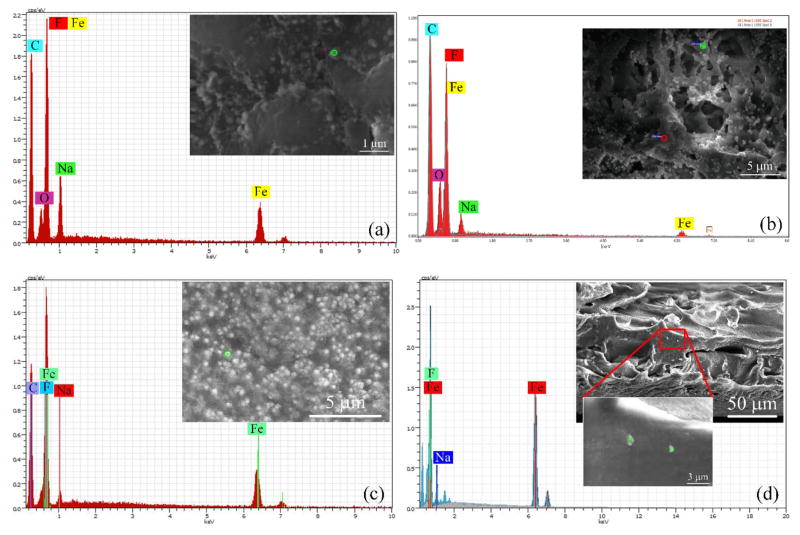
X-ray point-scans were performed on the surface and the cross-section of the HF and FS membranes to determine the metal loading in each membrane. These point-scans (green and red) and their spectra are shown in the Figure 6a–d. It can be seen that well-defined peaks of sodium occur around 1.0 keV, while peaks of iron (which is also overlapped with fluorine spectrum) occur around 0.6 and 6.4 keV. The atomic ratios (Fe/Na) on the outer and top surfaces of HF and FS are 1/2.2 and 3.8/1, respectively.
Figure 6.
SEM images and EDS spectra of PVDF-PAA-Fe hollow fiber and flat sheet membranes. (a) HF outer surface, (b) FIB cut of HF cross-section, (c) FS top surface, (d) FS cross-section.
Remarkably, in the FS membranes the amount of sodium with respect to iron is 8 times higher than the calculated value (2/1). This implies that not only did the ion exchange process occur but also that most of the iron present within the swollen structure of PAA was reduced to Fe NPs. For the cross-section part (Figure 6b), the atomic ratio for the HF is almost constant compared to the outer surface 2.15/1 (Na/Fe). The amount of both metals based on the counts is lower than the outer surface. In the FS membranes (Figure 6d), similar behavior of the top surface occurs but in lower proportions with a ratio of 1:1.57 (Na/Fe).
Particle Size Characterization
Characterization of particle size is necessary to calculate the NP specific surface area (as) which is essential in the heterogeneous catalytic dechlorination, since bulk particles can only degrade about 10% of organic-chlorinated compounds.20b Particle size has been discussed in a wide range of topics, such as geology, atmospheric sciences and engineering.32 Many of these studies have used physical separation of macro-particles (sieve analysis) with 3D digital models based on laser scans.33
For small particle characterization, most analyses are performed in solution using common methods such as DLS, transmission electron microscopy (TEM), atomic force microscopy (AFM), BET surface analysis or SEM picture analysis,34 including works related to Fe, Fe/Ni and Fe/Pd NPs.18b, 21, 35 For solid materials, SEM/TEM pictures are taken, calculating by direct measuring an average particle size, even with an image analysis software.36 Recent works have shown the potential of image analysis (2D metrics) for small particles, mostly TEM images in liquid phase.36–37 This work applies this concept on the SEM pictures from the membrane/particle nanocomposite to quantify the shape descriptors of the Fe NPs in 2D. These results were extrapolated to the definition of the particle size through statistical distributions.
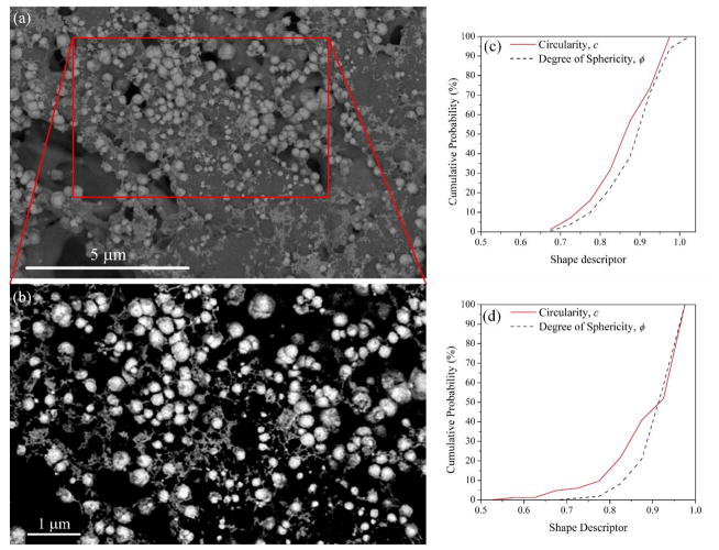
Using Image J on SEM pictures (Figure 7a) of the HF membrane (FS not shown), each image was adjusted to increase the contrast (Figure 7b), the particles were surrounded and highlighted; their perimeter (P), projected area (Ap) from the image, minimum circumscribed and maximum inscribed circles (dc and di, respectively) were calculated. 2D projection of each sphere was used to quantify how close each shape was to a perfect circle, and hence, how it is related to a sphere. Based on the parameters measured, particle shape factors were calculated using the Image J program. The factors taken into account were roundness (R = di·dc−1), its inverse (aspect ratio, AR) and circularity (c = 4πAp·P−2).38 Wadell’s degree of sphericity33, 39 (ϕ = deq·dc−1) was considered too, since it has been stated that ϕ accurately describes 3D particle shapes.39 Here, deq is the equivalent diameter of a circle with the same area as Ap. Based on circle and ellipse area formulas and emplacing Ap, deq, dc and di, it was found that ϕ2 = R. Each quantity will be close to 1 when the projected area is close to a circle.
Figure 7.
SEM imaging and shape descriptor distributions of Fe nanoparticles in PVDF-PAA-Fe membrane. (a) Through-Lens-Detector (TLD) Backscattered Electron Mode of hollow fiber, (b) zoom-in of (a) enhanced contrast for counting/sizing Fe nanoparticles, (c) circularity and degree of sphericity of Fe NPs in hollow fiber membranes, (d) circularity and degree of sphericity of Fe NPs in flat sheet membranes.
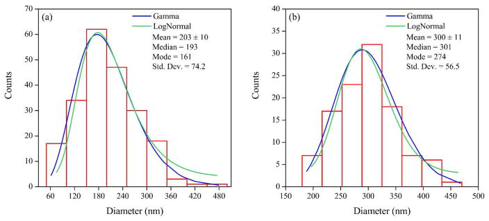
Figure 7c–d shows that almost 95% of the NPs can be considered spheres/spheroids32a, 32b, 40 with values of ϕ and c higher than 0.7. With this confirmation, the particle size can be defined by the equivalent diameter (deq) of a circle with the same area as Ap. The particle size distributions of Fe NPs inside HF and FS membranes are shown in Figure 8. Fitted lognormal and gamma distributions are frequently used to describe particle size, since they have multiplicative effects and the NPs grow randomly depending on their size.41 These distributions define the mean and the median as the characteristic value for the particle size.38, 41 The size distribution is statistically significant with p values less than one order of magnitude (Kolmogorov-Smirnov: D = 0.06, p = 0.16 for HF and D = 0.06, p = 0.25 for FS). The NP sizes are 193 and 301 nm for HF and FS membranes, respectively, which are in the range of the arithmetic means with 95% confidence. From the solution phase, the DLS analysis stablishes a NP size of around 132 nm, which is smaller than that obtained in the membranes. Note that the solution was sonicated and therefore, the nanoparticles were disaggregated; this aggregation does not occur in the membranes, giving them an operational advantage.
Figure 8.
Nanoparticle size distribution. (a) Hollow fiber membrane, (b) flat sheet membrane.
Reductive Dechlorination
To test the reactivity of the membranes, TCE was selected as a model compound for reductive dechlorination by the bimetallic Fe/Pd NPs inside the membranes. At pH 5.5 to 7.0, iron corrodes in a Fe/Pd system generating hydrogen when Pd is used as catalyst (Scheme 1). To promote Fe corrosion, Pd has to generate enough active sites on the NP surface.42 The Pd coating goes from 0.8 to 3.4 monolayers, which could cover a large enough proportion of the particles, giving them less active sites and in consequence, a nonlinear dependence at higher Pd concentrations.
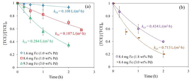
The Pd concentrations (relative to Fe) used are shown in Figure 9 and did not affect the average particle size. The batch reduction with metal (Fe/Pd) NPs follows a pseudo-first-order rate law:43
Figure 9.
TCE reduction by Fe/Pd nanoparticles immobilized in PVDF-PAA membranes. TCE concentration = 0.29 mM. Volume = 0.02 L. pH ≈ 5.5. T = 22 °C. (a) Hollow fiber (outer surface area= 10.9 cm2; particle diameter, deq = 193 nm; membrane thickness = 225 μm), (b) flat sheet (Top surface area = 17.3 cm2; particle diameter, deq = 301 nm; PVDF membrane thickness = 125 μm).
| (3) |
where kobs is the observed pseudo-first-order rate constant (h−1), C is the TCE concentration (mg/L) at time t (h), kSA is the surface-area-normalized rate constant related to the particle size (L/m2·h), ρm is the NP loading (g/L) and as (m2/g). Based on the particle size calculations, as is 3.94 and 2.52 m2/g, for HF and FS, respectively.
Figure 9 shows an exponential dechlorination behavior (1st order rate) at different times for each membrane. The decline in TCE concentration is lower as time passes because of mass transfer limitations from the bulk solution to the NP core. However, the kSA from HF obtained is higher (0.108 to 0.284 L/m2·h) to the reported (0.068 to 0.130 L/m2·h)5a, 20b, 44 with the same concentrations of Pd used (1 to 3 wt. % Pd). The dechlorination in HF membranes corroborated the increase in the dechlorination rate when the NPs have higher Pd concentration (Figure 9a).42c The kSA spiked up when FS membranes were used with the same iron loading as one of the samples of HF membranes (Figure 9b). Based on these results, it can be inferred that the Pd layer was defective at high concentrations or the sponge-like nature of both membranes provided a higher surface area, and hence, accessibility, which gave them more active sites for Fe corrosion, and subsequently higher dechlorination rates.
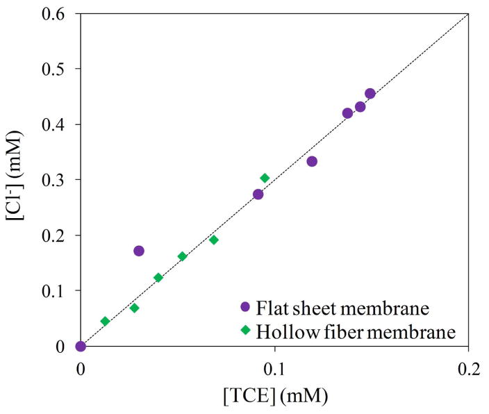
Chloride ion was also measured (Figure 10) to corroborate the complete dechlorination. Theoretically, chloride concentrations could be lower in the beginning of the reaction or not appreciable due to chloride adsorption by corrosion.18c, 45 A close correlation of the ratio Cl− formed to TCE consumed to the stoichiometric value of 3/1 (Cl−/TCE) was obtained. This result confirms that all TCE reacted with negligible presence of intermediates.
Figure 10.
Relation of TCE consumed/Cl− formed from TCE batch reduction by Fe/Pd nanoparticles. TCE concentration = 0.29 mM. Volume = 0.02 L. pH ≈ 5.5. T = 22 °C.
CONCLUSIONS
The current study presents the fabrication of a PVDF hollow fiber membrane by thermal induced phase separation with a porosity of nearly 60%, a pore size distribution with 69 % of pores smaller than 1.0 μm and an average size of 0.72 μm. The hollow fiber membranes were successfully hydrophilized by PVP cross-linking on top of the porous structure. This was corroborated by the increase of the hydrophilicity and surface free energy of the membranes (40.26 to 50.68 mJ/m2). The cross-linking of PVP on the surface, not only suggests free radical reaction, but also ring-opening and etherification due to the presence of ether bonds in the FTIR spectra.
We presented the functionalization of PVDF sponge-like membranes, hollow fiber and flat sheet, with a poly(acrylic acid) hydrogel and a subsequent in situ synthesis of bimetallic Fe/Pd nanoparticles. Flat sheet membranes showed a constant iron loading capacity (4.7 ± 0.3 g/m2). In contrast, hollow fiber membranes showed a variable iron loading (1.6 to 8.7 g/m2) possibly due to loss of the PVP coating during the functionalization with PAA.
A method previously not used in this field of nanoparticle size characterization within a membrane domain using image analyses of the SEM pictures was applied. These analyses show a close correlation between the degree of sphericity and the circularity of the particles, stating that 95% of the particles can be considered spherical and that this characteristic can be assumed when calculating particle size (diameter) for use in surface catalytic reaction calculations of specific surface area.
From the reactivity evaluation, the surface-area-normalized rate constants are almost four times higher with similar iron loadings to previous studies, both our own and others. Flat sheet membranes have a larger surface area due to their spongy nature. Hollow fiber membranes, on the other hand, show lower iron loadings than the flat sheet membranes. This behavior can be explained by the inability of ion exchange Na/Fe due to a decrease in the swelling of the hydrogel because changes in pH of the solutions used. Additionally, the hollow fiber membrane functionalization has been highly variable and can present hydrophobic patches or complete coating zones with hydrogel, which makes it partially inaccessible. These results imply that the sponge-like structure of the hollow fiber and flat sheet membranes increase the accessibility to the nanoparticle domain and hence, the reactivity of the species.
Acknowledgments
Funding Sources
Grant Number P42ES007380 from the National Institute of Environmental Health Sciences supported this project. NSF KY EPSCoR (1355438) program also provided partial support.
We want to thank the NIH-NIEHS-SRC program, University of Kentucky Environmental Research Training Laboratories, the Center of Membrane Sciences and KY NSF EPSCoR Membrane Pillar and the Robert E. Hemenway Writing Center. Hollow fiber Membranes were fabricated at the Singapore Membrane Technology Center, NTU (Singapore, Singapore). Flat sheet and spongy membranes used were fabricated through collaborative work with Nanostone (Oceanside CA, USA). The content is solely the responsibility of the authors and does not necessarily represent the official views of the National Institute of Environmental Health Sciences or the National Institutes of Health.
Footnotes
Notes
The authors declare no competing financial interest.
References
- 1.Sharma VK, Zboril R, Varma RS. Ferrates: Greener Oxidants with Multimodal Action in Water Treatment Technologies. Accounts of Chemical Research. 2015;48(2):182–191. doi: 10.1021/ar5004219. [DOI] [PubMed] [Google Scholar]
- 2.Liu F, Hashim NA, Liu Y, Abed MRM, Li K. Progress in the production and modification of PVDF membranes. J Membrane Sci. 2011;375(1–2):1–27. [Google Scholar]
- 3.Liang S, Kang Y, Tiraferri A, Giannelis EP, Huang X, Elimelech M. Highly Hydrophilic Polyvinylidene Fluoride (PVDF) Ultrafiltration Membranes via Postfabrication Grafting of Surface-Tailored Silica Nanoparticles. Acs Appl Mater Inter. 2013;5(14):6694–6703. doi: 10.1021/am401462e. [DOI] [PubMed] [Google Scholar]
- 4.(a) Ulbricht M. Polymer. 2006. Advanced functional polymer membranes. [Google Scholar]; (b) Lewis SR, Smuleac V, Xiao L, Bhattacharyya D. Responsive Membranes and Materials. John Wiley & Sons, Ltd; 2012. Tunable Separations, Reactions, and Nanoparticle Synthesis in Functionalized Membranes; pp. 97–142. [Google Scholar]
- 5.(a) Smuleac V, Varma R, Sikdar S, Bhattacharyya D. Green Synthesis of Fe and Fe/Pd Bimetallic Nanoparticles in Membranes for Reductive Degradation of Chlorinated Organics. J Membrane Sci. 2011;379(1–2):131–137. doi: 10.1016/j.memsci.2011.05.054. [DOI] [PMC free article] [PubMed] [Google Scholar]; (b) Markova Z, Novak P, Kaslik J, Plachtova P, Brazdova M, Jancula D, Siskova KM, Machala L, Marsalek B, Zboril R, Varma R. Iron(II,III)–Polyphenol Complex Nanoparticles Derived from Green Tea with Remarkable Ecotoxicological Impact. ACS Sustainable Chemistry & Engineering. 2014;2(7):1674–1680. [Google Scholar]
- 6.Smuleac V, Varma R, Baruwati B, Sikdar S, Bhattacharyya D. Nanostructured membranes for enzyme catalysis and green synthesis of nanoparticles. Chem Sus Chem. 2011;4(12):1773–7. doi: 10.1002/cssc.201100211. [DOI] [PubMed] [Google Scholar]
- 7.(a) Jian X, Dibakar B. Fe/Pd Nanoparticle Immobilization in Microfiltration Membrane Pores: Synthesis, Characterization, and Application in the Dechlorination of Polychlorinated Biphenyls. Ind Eng Chem Res. 2007:46. [Google Scholar]; (b) Lewis SR, Datta S, Gui M, Coker EL, Huggins FE, Daunert S, Bachas L, Bhattacharyya D. Reactive nanostructured membranes for water purification. P Natl Acad Sci USA. 2011;108(21):8577–8582. doi: 10.1073/pnas.1101144108. [DOI] [PMC free article] [PubMed] [Google Scholar]; (c) Saad A, Takigawa D, Bhattacharyya D. Development of bench and full-scale temperature and pH responsive functionalized PVDF membranes with tunable properties. Journal of Membrane …. 2014 doi: 10.1016/j.memsci.2014.01.033. [DOI] [PMC free article] [PubMed] [Google Scholar]
- 8.(a) Xu Z, Huang X, Wan L. Surface engineering of polymer membranes. 2009 [Google Scholar]; (b) Dickson JM, Childs RF, McCarry BE, Gagnon DR. Development of a coating technique for the internal structure of polypropylene microfiltration membranes. J Membrane Sci. 1998;148(1):25–36. [Google Scholar]
- 9.(a) Franken ACM, Nolten JAM, Mulder MHV, Bargeman D, Smolders CA. Wetting criteria for the applicability of membrane distillation. J Membrane Sci. 1987;33(3):315–328. [Google Scholar]; (b) Gabelman A, Hwang ST. Hollow fiber membrane contactors. J Membrane Sci. 1999;159(1–2):61–106. [Google Scholar]; (c) Nunes SP, Peinemann KV John, W.; Sons. Membrane technology in the chemical industry. Wiley-VCH; Weinheim: 2006. [Google Scholar]
- 10.Changsheng Z, Shengqiang N, Min T, Shudong S. Polymeric pH-sensitive membranes—A review. Prog Polym Sci. 2011;36 [Google Scholar]
- 11.(a) Yu K, Chung TS, Gryta M. Hydrophobic PVDF hollow fiber membranes with narrow pore size distribution and ultra-thin skin for the fresh water production through membrane distillation. Chem Eng Sci. 2008 [Google Scholar]; (b) Zhang Q, Lu X, Zhao L. Preparation of Polyvinylidene Fluoride (PVDF) Hollow Fiber Hemodialysis Membranes. Membranes. 2014;4(1):81–95. doi: 10.3390/membranes4010081. [DOI] [PMC free article] [PubMed] [Google Scholar]
- 12.Liu F, Hashim N, Liu Y, Abed M, Li K. Progress in the production and modification of PVDF membranes. Fuel and Energy Abstracts. 2011 [Google Scholar]
- 13.Wenzhong M, Jun Z, Shuangjun C, Xiaolin W. β-Phase of poly(vinylidene fluoride) formation in poly(vinylidene fluoride)/poly(methyl methacrylate) blend from solutions. Appl Surf Sci. 2008 [Google Scholar]
- 14.Du JR, Peldszus S, Huck PM, Feng X. Modification of poly(vinylidene fluoride) ultrafiltration membranes with poly(vinyl alcohol) for fouling control in drinking water treatment. Water Res. 2009;43(18):4559–4568. doi: 10.1016/j.watres.2009.08.008. [DOI] [PubMed] [Google Scholar]
- 15.Bi QY, Li Q, Tian Y, Lin YK, Wang XL. Hydrophilic modification of poly(vinylidene fluoride) membrane with poly(vinyl pyrrolidone) via a cross-linking reaction. J Appl Polym Sci. 2013;127(1):394–401. [Google Scholar]
- 16.(a) Ross GJ, Watts JF, Hill MP, Morrissey P. Surface modification of poly (vinylidene fluoride) by alkaline treatment1. The degradation mechanism. Polymer. 2000 [Google Scholar]; (b) LaiZhou S, Zhang Z, ShiZhe… S. Preparation and Characterization of the Modified Polyvinylidene Fluoride (PVDF) Hollow Fibre Microfiltration Membrane. J Mater Sci Technol. 2007 [Google Scholar]
- 17.(a) Pathak TS, Chung KY. Surface Modification and Permeation Characteristics of PVDF Membrane afterGraft Polymerization Using PolarMonomer. J Ind Eng Chem. 2006 [Google Scholar]; (b) AB Grafting: a versatile means to modify polymersTechniques, factors and applications. Prog Polym Sci. 2004;29 [Google Scholar]
- 18.(a) Zhang W-x. Nanoscale Iron Particles for Environmental Remediation: An Overview. J Nanopart Res. 2003;5(3–4):323–332. [Google Scholar]; (b) He F, Zhao D, Liu J, Roberts CB. Stabilization of Fe–Pd Nanoparticles with Sodium Carboxymethyl Cellulose for Enhanced Transport and Dechlorination of Trichloroethylene in Soil and Groundwater. Ind Eng Chem Res. 2007;46(1):29–34. [Google Scholar]; (c) Gotpagar J, Grulke E, Tsang T, Bhattacharyya D. Reductive dehalogenation of trichloroethylene using zero-valent iron. Environ Prog. 1997;16(2):137–143. [Google Scholar]; (d) Kim EJ, Murugesan K, Kim JH, Tratnyek PG, Chang YS. Remediation of Trichloroethylene by FeS-Coated Iron Nanoparticles in Simulated and Real Groundwater: Effects of Water Chemistry. Ind Eng Chem Res. 2013;52(27):9343–9350. [Google Scholar]
- 19.Gui M, Ormsbee LE, Bhattacharyya D. Reactive Functionalized Membranes for Polychlorinated Biphenyl Degradation. Ind Eng Chem Res. 2013;52(31):10430–10440. doi: 10.1021/ie400507c. [DOI] [PMC free article] [PubMed] [Google Scholar]
- 20.(a) He F, Zhao D. Hydrodechlorination of trichloroethene using stabilized Fe-Pd nanoparticles: Reaction mechanism and effects of stabilizers, catalysts and reaction conditions. Applied Catalysis B: Environmental. 2008;84(3–4):533–540. [Google Scholar]; (b) Xu J, Bhattacharyya D. Fe/Pd nanoparticle immobilization in microfiltration membrane pores: Synthesis, characterization, and application in the dechlorination of polychlorinated biphenyls. Ind Eng Chem Res. 2007;46(8):2348–2359. [Google Scholar]
- 21.Sun YP, Li XQ, Cao J, Zhang WX, Wang HP. Characterization of zero-valent iron nanoparticles. Adv Colloid Interface Sci. 2006;120(1–3):47–56. doi: 10.1016/j.cis.2006.03.001. [DOI] [PubMed] [Google Scholar]
- 22.(a) Jurak M, Chibowski E. Surface free energy and topography of mixed lipid layers on mica. Colloids Surf B Biointerfaces. 2010;75(1):165–74. doi: 10.1016/j.colsurfb.2009.08.034. [DOI] [PubMed] [Google Scholar]; (b) Pogorzelski SJ, Berezowski Z, Rochowski P, Szurkowski J. A novel methodology based on contact angle hysteresis approach for surface changes monitoring in model PMMA-Corega Tabs system. Appl Surf Sci. 2012;258(8):3652–3658. [Google Scholar]; (c) Chibowski E. Surface free energy of a solid from contact angle hysteresis. Adv Colloid Interface Sci. 2003;103(2):149–72. doi: 10.1016/S0001-8686(02)00093-3. [DOI] [PubMed] [Google Scholar]
- 23.(a) Duca MD, Plosceanu CL, Pop T. Surface modifications of polyvinylidene fluoride (PVDF) under rf Ar plasma. Polym Degrad Stabil. 1998;61(1):65–72. [Google Scholar]; (b) Huang FL, Wang QQ, Wei QF, Gao WD, Shou HY, Jiang SD. Dynamic wettability and contact angles of poly(vinylidene fluoride) nanofiber membranes grafted with acrylic acid. Express Polym Lett. 2010;4(9):551–558. [Google Scholar]; (c) Kuo CY, Lin HN, Tsai HA, Wang DM, Lai JY. Fabrication of a high hydrophobic PVDF membrane via nonsolvent induced phase separation. Desalination. 2008;233(1–3):40–47. [Google Scholar]; (d) Wu TF, Zhou BM, Zhu T, Shi J, Xu ZW, Hu CS, Wang JJ. Facile and low-cost approach towards a PVDF ultrafiltration membrane with enhanced hydrophilicity and antifouling performance via graphene oxide/water-bath coagulation. Rsc Adv. 2015;5(11):7880–7889. [Google Scholar]
- 24.(a) Sun M, He Y, Ye Y, Yang W, Yin M. Nucleophilic Substitution of Tetrachloroperylene Diimide in Fluorescent Polyvinylpyrrolidone Film. Macromol Chem Phys. 2014;215(6):493–498. [Google Scholar]; (b) Yin M, Ye Y, Sun M, Kang N, Yang W. Facile one-pot synthesis of a polyvinylpyrrolidone-based self-crosslinked fluorescent film. Macromol Rapid Commun. 2013;34(7):616–20. doi: 10.1002/marc.201200750. [DOI] [PubMed] [Google Scholar]
- 25.Wienk IM, Meuleman EEB, Borneman Z, Vandenboomgaard T, Smolders CA. Chemical Treatment of Membranes of a Polymer Blend - Mechanism of the Reaction of Hypochlorite with Poly(Vinyl Pyrrolidone) J Polym Sci Pol Chem. 1995;33(1):49–54. [Google Scholar]
- 26.(a) Zhang QG, Hu WW, Zhu AM, Liu QL. UV-crosslinked chitosan/polyvinylpyrrolidone blended membranes for pervaporation. RSC Adv. 2013;3(6):1855–1861. [Google Scholar]; (b) Lopérgolo LC, Lugão AB, Catalani LH. Direct UV photocrosslinking of poly(N-vinyl-2-pyrrolidone) (PVP) to produce hydrogels. Polymer. 2003;44(20):6217–6222. [Google Scholar]
- 27.(a) Fechine GJM, Barros JAG, Catalani LH. Poly(N-vinyl-2-pyrrolidone) hydrogel production by ultraviolet radiation: new methodologies to accelerate crosslinking. Polymer. 2004;46(1):283. [Google Scholar]; (b) Kadłubowski S, Henke A, Ulański P, Rosiak JM, Bromberg L, Hatton TA. Hydrogels of polyvinylpyrrolidone (PVP) and poly(acrylic acid) (PAA) synthesized by photoinduced crosslinking of homopolymers. Polymer. 2007;48(17):4974–4981. [Google Scholar]
- 28.Anderson C, Rodriguez… F. Crosslinking aqueous poly (vinyl pyrrolidone) solutions by persulfate. Journal of Applied …. 1979 [Google Scholar]
- 29.(a) Kang JS, Kim KY, Lee YM. Preparation of PVP immobilized microporous chlorinated polyvinyl chloride membranes on fabric and their hydraulic permeation behavior. J Membrane Sci. 2003;214(2):311–321. [Google Scholar]; (b) Wienk IM. Ultrafiltration membranes from a polymer blend : hollow fiber preparation and characterization. 1993 [s.n.]: [S.l.] [Google Scholar]; (c) Xu WJ, Chen HZ, Li HY, Wang M. Fabrication of carbon black/crosslinked poly(vinyl pyrrolidone) core-shell nanoparticles stable in water. Colloid Surface A. 2005;266(1–3):68–72. [Google Scholar]
- 30.Basha MAF. Magnetic and optical studies on polyvinylpyrrolidone thin films doped with rare earth metal salts. Polym J. 2010;42(9):728–734. [Google Scholar]
- 31.Taylor LS, Langkilde FW, Zografi G. Fourier transform Raman spectroscopic study of the interaction of water vapor with amorphous polymers. J Pharm Sci-Us. 2001;90(7):888–901. doi: 10.1002/jps.1041. [DOI] [PubMed] [Google Scholar]
- 32.(a) Rodriguez JM, Edeskär T, Knutsson S. Particle shape quantities and measurement Techniques–A review. Electronic Journal of Geotechnical Engineering. 2013;18:169–198. [Google Scholar]; (b) Holdich RG. Fundamentals of particle technology. Midland Information Technology and Pub; Shepshed: 2002. [Google Scholar]; (c) Petty GW, Huang W. The Modified Gamma Size Distribution Applied to Inhomogeneous and Nonspherical Particles: Key Relationships and Conversions. Journal of the Atmospheric Sciences. 2011;68(7):1460–1473. [Google Scholar]
- 33.Hayakawa Y, Oguchi T. Evaluation of gravel sphericity and roundness based on surface-area measurement with a laser scanner. Comput Geosci-Uk. 2005;31(6):735–741. [Google Scholar]
- 34.(a) Thomas V, Namdeo M, Murali Mohan Y, Bajpai SK, Bajpai M. Review on Polymer, Hydrogel and Microgel Metal Nanocomposites: A Facile Nanotechnological Approach. Journal of Macromolecular Science, Part A. 2007;45(1):107–119. [Google Scholar]; (b) Bueno VB, Catalani LH, Daghastanli KRP, Cuccovia IM, Chaimovich H. Preparation of Pvp Hydrogel Nanoparticles Using Lecithin Vesicles. Quimica Nova. 2010;33(10):2083–2087. [Google Scholar]; (c) Weibel A, Bouchet R, Boulc F, Knauth P. The Big Problem of Small Particles: A Comparison of Methods for Determination of Particle Size in Nanocrystalline Anatase Powders. Chem Mater. 2005;17(9):2378–2385. [Google Scholar]
- 35.(a) Gui M, Smuleac V, Ormsbee L, Sedlak D, Bhattacharyya D. Iron oxide nanoparticle synthesis in aqueous and membrane systems for oxidative degradation of trichloroethylene from water. J Nanopart Res. 2012;14(5):1–16. doi: 10.1007/s11051-012-0861-1. [DOI] [PMC free article] [PubMed] [Google Scholar]; (b) Parshetti GK, Doong R-a. Dechlorination of trichloroethylene by Ni/Fe nanoparticles immobilized in PEG/PVDF and PEG/nylon 66 membranes. Water Res. 2009;43(12):3086–3094. doi: 10.1016/j.watres.2009.04.037. [DOI] [PubMed] [Google Scholar]
- 36.Bell NC, Minelli C, Tompkins J, Stevens MM, Shard AG. Emerging Techniques for Submicrometer Particle Sizing Applied to Stöber Silica. Langmuir. 2012;28(29):10860–10872. doi: 10.1021/la301351k. [DOI] [PubMed] [Google Scholar]
- 37.(a) Woehrle GH, Hutchison JE, Ozkar S, Finke RG. Analysis of nanoparticle Transmission Electron Microscopy data using a public-domain image-processing program, Image. Turk J Chem. 2006;30(1):1–13. [Google Scholar]; (b) Fisker R, Carstensen JM, Hansen MF, Bødker F, Mørup S. Estimation of Nanoparticle Size Distributions by Image Analysis. J Nanopart Res. 2000;2(3):267–277. [Google Scholar]
- 38.Olson E. Particle Shape Factors and Their Use in Image Analysis Part 1: Theory. JOURNAL OF GXP COMPLIANCE. 2011;15(3):85–96. [Google Scholar]
- 39.Cavarretta I, O’Sullivan C, Coop MR. Applying 2D shape analysis techniques to granular materials with 3D particle geometries. AIP Conference Proceedings. 2009;1145(1):833–836. [Google Scholar]
- 40.Le Roux JP. A Hydrodynamic Classification of Grain Shapes. Journal of Sedimentary Research. 2004;74(1):135–143. [Google Scholar]
- 41.Fátima Vaz M, Fortes MA. Grain size distribution: The lognormal and the gamma distribution functions. Scripta Metallurgica. 1988;22(1):35–40. [Google Scholar]
- 42.(a) Wang C-B, Zhang W-x. Synthesizing Nanoscale Iron Particles for Rapid and Complete Dechlorination of TCE and PCBs. Environ Sci Technol. 1997;31(7):2154–2156. [Google Scholar]; (b) Wang X, Chen C, Liu H, Ma J. Preparation and characterization of PAA/PVDF membrane-immobilized Pd/Fe nanoparticles for dechlorination of trichloroacetic acid. Water Res. 2008;42(18):4656–64. doi: 10.1016/j.watres.2008.08.005. [DOI] [PubMed] [Google Scholar]; (c) Smuleac V, Bachas L, Bhattacharyya D. Aqueous-phase synthesis of PAA in PVDF membrane pores for nanoparticle synthesis and dichlorobiphenyl degradation. J Membrane Sci. 2010;346(2):310–317. doi: 10.1016/j.memsci.2009.09.052. [DOI] [PMC free article] [PubMed] [Google Scholar]
- 43.Ebert M, Köber R, Parbs A, Plagentz V, Schäfer D, Dahmke A. Assessing degradation rates of chlorinated ethylenes in column experiments with commercial iron materials used in permeable reactive barriers. Environ Sci Technol. 2006;40(6):2004–2010. doi: 10.1021/es051720e. [DOI] [PubMed] [Google Scholar]
- 44.Hernández S, Papp JK, Bhattacharyya D. Iron-Based Redox Polymerization of Acrylic Acid for Direct Synthesis of Hydrogel/Membranes and Metal Nanoparticles for Water Treatment. Ind Eng Chem Res. 2014;53(3):1130–1142. doi: 10.1021/ie403353g. [DOI] [PMC free article] [PubMed] [Google Scholar]
- 45.Schrick B, Blough JL, Jones AD, Mallouk TE. Hydrodechlorination of Trichloroethylene to Hydrocarbons Using Bimetallic Nickel–Iron Nanoparticles. Chem Mater. 2002;14(12):5140–5147. [Google Scholar]
- 46.Wu S. Calculation of Interfacial Tension in Polymer Systems. J Polym Sci Pol Sym. 1971;34(34):19. [Google Scholar]
- 47.Hayama M, Yamamoto K, Kohori F, Uesaka T, Ueno Y, Sugaya H, Itagaki I, Sakai K. Nanoscopic behavior of polyvinylpyrrolidone particles on polysulfone/polyvinylpyrrolidone film. Biomaterials. 2004;25(6):1019–28. doi: 10.1016/s0142-9612(03)00629-x. [DOI] [PubMed] [Google Scholar]
- 48.DeMejo LP, Rimai D, Sharpe LH. Fundamentals of adhesion and interfaces. Gordon and Breach Science Publishers; Australia: 1999. [Google Scholar]
- 49.O’neill L, O’hare LA, Goodwin AJ. Google Patents. 2006. Method for coating a substrate using plasma. [Google Scholar]
- 50.Vargaftik NB, Volkov BN, Voljak LD. International Tables of the Surface Tension of Water. Journal of Physical and Chemical Reference Data. 1983;12(3):817–820. [Google Scholar]


