Abstract
In medical imaging, clinicians, researchers and technicians have begun to use 3D printing to create specialized phantoms to replace commercial ones due to their customizable and iterative nature. Presented here is the design of a 3D printed open source, reusable magnetic resonance imaging (MRI) phantom, capable of flood-filling, with removable samples for measurements of contrast agent solutions and reference standards, and for use in evaluating acquisition techniques and image reconstruction performance. The phantom was designed using SolidWorks, a computer-aided design software package. The phantom consists of custom and off-the-shelf parts and incorporates an air hole and Luer Lock system to aid in flood filling, a marker for orientation of samples in the filled mode and bolt and tube holes for assembly. The cost of construction for all materials is under $90. All design files are open-source and available for download. To demonstrate utility, B0 field mapping was performed using a series of gadolinium concentrations in both the unfilled and flood-filled mode. An excellent linear agreement (R2>0.998) was observed between measured relaxation rates (R1/R2) and gadolinium concentration. The phantom provides a reliable setup to test data acquisition and reconstruction methods and verify physical alignment in alternative nuclei MRI techniques (e.g. carbon-13 and fluorine-19 MRI). A cost-effective, open-source MRI phantom design for repeated quantitative measurement of contrast agents and reference standards in preclinical research is presented. Specifically, the work is an example of how the emerging technology of 3D printing improves flexibility and access for custom phantom design.
Keywords: Open Source, MRI, Phantom, Standards, 3D Printing, Preclinical
1. Introduction
Rapid prototyping, or 3D printing, is emerging for medical applications in both the clinical and preclinical domains (Mitsouras et al 2015). Some clinical examples of applied 3D printing that have been investigated to date include dental models for orthodontics (Hazeveld et al 2014), surgical planning and anatomical visualization for neurosurgery and cardiovascular procedures (Wurm et al 2004, Kim et al 2008, Sodian et al 2008) and patient specific bone prostheses for orthopedics (Harrysson et al 2007). The custom nature of the patient specific devices needed in medicine make them uniquely suitable to 3D printing, which is designed to make a single part at a time according to a defined specification. Further, the complex shapes of devices that are designed around the organic shapes from patient imaging data can often only be made with 3D printing, which is not constrained by the limitations of conventional fabrication techniques.
An application for which 3D printing techniques can have a particularly large impact is in the creation of custom imaging phantoms (Shmueli et al 2007, Gallas et al 2015, Chen et al 2012). Phantoms are tools for calibration of imaging equipment, quality control testing, technique validation and, when appropriate, for replacement of tissue in imaging experiments (Bieniosek et al 2015, Mashal et al 2011, Lazebnik et al 2005). Commercial phantoms are available, but are often costly and may not be perfectly adapted to a desired application. With the design and fabrication tools available today it is possible to create custom phantoms at relatively low cost. This is especially true in the field of magnetic resonance imaging (MRI). MRI phantoms in the clinical setting are designed to monitor system performance, analyze image artifacts and validate quantitative techniques (Anderson et al 2014, Khan et al 2012, Kasten et al 2016, Moon and Hornak 2010, Shmueli et al 2007). While MR phantoms designed specifically for preclinical MR systems exist (O’Callaghan et al 2014, Yoshimaru et al 2014), they tend to be simplified and ad hoc compared to MR phantoms for clinical systems due to the non-standard bore and RF-coil volumes used in different small animal imaging applications.
Therefore, there is a need for custom quantitative phantoms that enable validation of imaging techniques in the preclinical setting. For example, in our initial application we desire a phantom to compare solutions of contrast agents for optimizing concentration for imaging and as a reference standard to relate image contrast to chemical concentration with a reproducible setup to support reusability and flexibility for quantitative comparison of samples. The design needs to be cost-effective for a specialized preclinical application and sufficiently small to fit within the magnet bore and radiofrequency (RF) coils for a variety of set-ups required in preclinical settings. Here, we present a simple, open-source, 3D printed solution for a preclinical MRI phantom designed with flood filling capability. This phantom has many applications in both its filled and unfilled state. Sample data and images are included with the phantom being used for quantitative measures of MR contrast agent relaxation properties, as well as using the phantom to test image acquisition and reconstruction with carbon-13 (13C) samples and to test fluorine-19 (19F) image alignment with a reference proton (1H) image. Design features of the phantom include easy replacement of samples and water filling with a syringe. The phantom is open source and all design files are available for download.
2. Methods
2.1 Phantom Fabrication
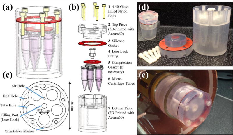
Several important design components were included when conceptualizing this preclinical phantom. First, easy sample replacement was desired to allow for reuse and flexibility. Second, a Luer Lock system was included for easy filling of the phantom with water using a syringe. Third, size-demands of small preclinical RF coils limited the number of samples to five and the overall size to a diameter of 38 mm and 50 mm, depending on the RF coil. The phantom was designed using SolidWorks (Dassault Systemes, Velizy-Villacoublay, France), a computer-aided design (CAD) software package. The complete design consists of seven parts, including two custom 3D printed parts, two custom parts laser cut from a sheet of silicone rubber and three commercial components (Table 1). The 3D printed parts were printed using a Viper Si 2 Stereolithography system (3D Systems, Rock Hill, SC) using Accura60, a photopolymer (3D Systems). Once printed, the five holes on the top of the phantom bottom piece (Figure 1(b), #2) were tapped with a 4–40 tap to allow phantom assembly. The silicone pieces were laser cut using a PLS6.75 laser cutting system (Universal Laser Systems, Scottsdale, AZ) out of a thin sheet of silicone rubber (McMaster-Carr, Elmhurst, IL). Small volume (0.5 mL) micro-centrifuge tubes (Eppendorf AG, Hamburg, Germany) were modified by trimming the edges on the cap of the tube to enable them to fit into the phantom.
Table 1.
Parts list for the open source, 3D printed preclinical MRI phantom
| Part #a |
Description | Vendor | Part # | Quantity | Cost |
|---|---|---|---|---|---|
| 1 | Glass-Filled Nylon Bolts | McMaster-Carr | 91221A218 | 5 | $2.28 |
| 2 | Phantom Top Piece | Custom | N/A | 1 | $46.00b |
| 3 | Silicone Gasket | Custom | N/A | 1 | $4.00 |
| 4 | Luer Fitting (10–32 Thread) | McMaster-Carr | 51525K21 | 1 | $0.57 |
| 5 | Silicone Compression Piece | Custom | N/A | 1 | $4.00 |
| 6 | Modified Micro-Centrifuge Tubes | Eppendorf | 022431064 | 5 | $0.55 |
| 7 | Phantom Bottom Piece | Custom | N/A | 1 | $32.00b |
|
| |||||
| Total | $89.40 | ||||
Part #’s correspond to those listed in Figure 1(b).
2017 prices, actual prices will also vary depending on the printing method and printer used.
Figure 1.
The schematic design of the MRI phantom is shown as a 3D CAD model (a) and in an exploded view (b) with parts (custom and purchased) listed. An axial view of bottom piece (c) depicts several design features including the air hole and filling port for air release and water filling, respectively. A notch is included as an orientation marker in filled mode along one of the micro-centrifuge tube holes. The overall maximum diameter of the phantom is 36 mm with room for five micro-centrifuge tubes with 8.25 mm diameters each. Photographs of both the disassembled phantom (d) and the assembled phantom outside (d, inset) and within the RF imaging coil (e) are also shown.
2.2 Phantom Assembly
All compounds used are available from Sigma-Aldrich (St. Louis, MO) unless specifically noted. Gadolinium (Gd)-relaxation tubes were prepared in the micro-centrifuge tubes with tap water and varying concentrations (0.0, 0.25, 0.5, 0.75, 1.0 mM) of gadobenate dimeglumine (MultiHance, Bracco Diagnostics, Inc. Princeton, NJ). 13C tubes were filled with thermal 13C species acquired from Cambridge Isotope Laboratories, Inc. (Tewksbury, MA) including 9.4 M 13C-urea, 2.1 M [1-13C]glycine, 2.0 M [1,4-13C2]succinic acid, and [1-13C]Na-L-lactate doped with 8.5 mM, 5.4 mM, 4.0 mM, and 6.3 mM of gadobenate dimeglumine, respectively. 19F tubes with mixed relative volumes of perfluoro-15-crown-5 ether (PFCE) (Exfluoro, Round Rock, TX) or isoflurane (Piramal, Bethlehem, PA) were prepared for a total volume of about 700 µL. Volume ratios between PFCE and isoflurane were 1:0, 0.75:0.25, 0.5:0.5, 0.25:0.75, and 0:1 PFCE:isoflurane. Tubes were then placed into the tube holes within the phantom and orientated using the alignment marker on the phantom’s bottom piece. Using a syringe with the included fitting, the chamber around the micro-centrifuge tubes was flood-filled with water. Next, the silicone compression piece was placed over the micro-centrifuge tubes, if necessary, and the silicone gasket was placed on top of the phantom bottom piece, keeping the holes aligned. Lastly, the phantom top piece was placed over the silicone gasket and the nylon bolts were used to seal the phantom top piece and the phantom bottom piece together, resulting in a filled and assembled phantom ready for imaging.
2.3 MR Imaging
All MR data were acquired on a 4.7 T preclinical MRI system (Agilent Technologies, Santa Clara, CA). B0 mapping and relaxometry measurements used a home-built volumetric quadrature MRI coil tunable to the 1H Larmor frequency (200 MHz). 19F imaging also utilized this home-built MRI coil but with it retuned and matched to the 19F Larmor frequency (188 MHz). 13C imaging was performed with a 1H/13C dual-tuned volumetric coil (Doty Scientific, Columbia, SC). A 2D spoiled gradient-echo acquisition, repeated with multiple echo times (TE) with a single echo per repetition time (TR) (TR = 10.20 ms, TE = 2.3 – 8.0 ms, echo spacing (ΔTE) = 0.3 ms, flip angle = 20°), was used for B0 field mapping. A 2D single echo spin-echo inversion recovery pulse sequence (inversion time (TI) = 20, 50, 100, 250, 500, 1000, 2000, 4000 ms, TE = 12.65 ms, TR = 6.0 s) and a 2D single echo spin-echo pulse sequence (TE = 15, 30, 45, 60, 75, 100, 115, 130 ms, TR = 2.0 s) were used to measure T1 and T2 for Gd-relaxometry experiments, respectively. A single 2 mm thick slice was acquired with a receiver bandwidth (BW) = 100 kHz, field-of-view = 40 × 40 mm2, matrix = 128 × 128, signal averages = 1 for the B0 mapping and Gd-relaxometry imaging sequences. Multi-spectral imaging of thermal 13C species was performed by acquiring a 2D spoiled gradient-echo, constant density spiral acquisition with 5 separate echoes at the resonant frequency of 13C-urea (TR = 110 ms, TE1 = 1.00 ms, ΔTE = 2.77 ms, field-of-view = 64 × 64 mm2, matrix = 21 × 21, slice thickness = 5 mm, BW = 250 kHz, flip angle = 90°, signal averages = 20). For 19F imaging, a chemical shift encoding acquisition was utilized to enable separation of the PFCE signal from the isoflurane signal during image reconstruction. This was a 3D spoiled gradient-echo acquisition repeated with multiple echo times tuned to 19F frequency (TR = 10.0 ms, TE = 2.3 ms, ΔTE = 0.33 ms, 6 echoes, field-of-view = 32 × 32 × 48 mm3, matrix = 96 × 96 × 24, BW = 30 kHz, flip angle = 10°, signal averages = 1).
2.4 Image Analysis
Image processing was performed in MATLAB 2015b (MathWorks, Natick, MA). Two echoes (TE = 2.3 and 8.0 ms) of the multi-TE data set were used to derive the B0 map (Nayak and Nishimura 2000). Images were first smoothed with a Gaussian filter and phase unwrapping was performed (Goldstein et al 1988, Ghiglia and Pritt 1998) prior to B0 field calculations. T1 and T2 estimates were fit to a mono-exponential signal recovery and decay model, respectively. Images of the individual thermal 13C species were generated using a least-squares, iterative reconstruction technique (Reeder et al 2007). The multi-echo chemical shift encoded 19F data was reconstructed using a non-linear least-squares k-space estimation. Only the PFCE signal, with isoflurane signal is displayed in the images. Details on the chemical shift encoded 19F MRI acquisition and reconstruction can be found elsewhere (Ludwig et al 2017).
3. Results
The preclinical phantom consists of custom and off-the-shelf components, which are detailed in a parts list (Table 1). Total cost of parts is about $90. All files necessary to recreate the custom components are available for download at https://morgridge.org/designs/.
Figure 1 displays the schematic design and assembly of the preclinical phantom. The 3D computer-aided design software (CAD) model and its exploded view are shown in Figure 1(a) and Figure 1(b), respectively. Key design features are shown in Figure 1(c), including an air hole and Luer Lock system to aid in flood filling, a marker for orientation of samples in the filled mode and bolt and tube holes for assembly. Photographs of the phantom in disassembled (Figure 1(d)) and assembled (Figure 1(d) inset) states, as well as positioned within the RF coil bore (Figure 1(e)) illustrate the preclinical phantom’s compact, waterproof design compatible with a 38 mm wide volume coil designed for a 4.7 T, 120 mm horizontal bore, preclinical MRI scanner.
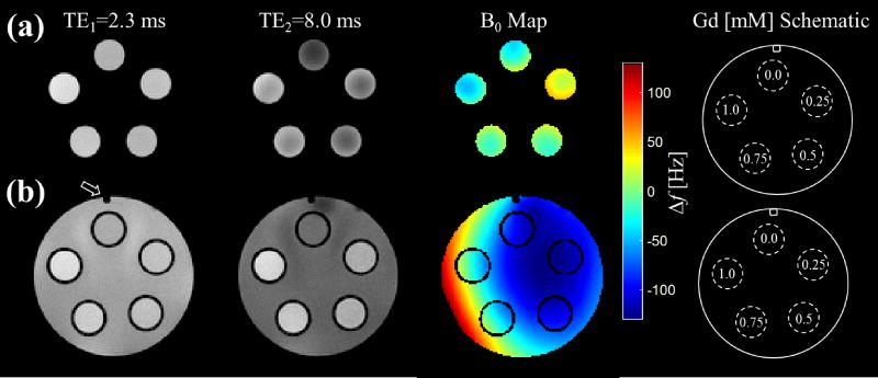
The phantom is capable of being a simple alignment tool for samples or to be flood-filled for imaging samples surrounded by water. For example, an axial slice orientation is convenient for 2D imaging of all tubes in a single field-of-view without voxel overlap. High-resolution gradient-echo MR images at two TEs with the generated B0 field maps for a series of Gd-doped water solutions are shown in Figure 2 in both the unfilled mode (Figure 2(a)) and the flood-filled mode (Figure 2(b)). The orientation marker, noted by the arrow, is observable in the filled mode and is also shown on the Gd concentration schematic.
Figure 2.
A 2D multi-echo gradient-echo sequence is used for both the unfilled (a) and filled (b) state of the phantom to calculate the B0 field inhomogeneity. The difference in phase between a short echo image, TE1, in the first column and a long echo image, TE2, in the second column is used to estimate the spatial variation in frequency (Δf) in the B0 field shown in the third column. The orientation marker is clearly visible in the filled state and is noted on TE1 and in the phantom schematic. The five micro-centrifuge tubes were filled with varying gadolinium (Gd) concentrations, which are shown in the schematic.
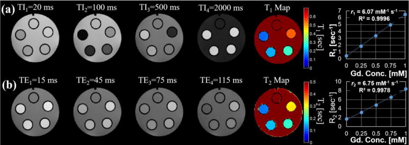
A wide range of measurement applications are possible with the phantom. One such application is the quantitative determination of concentration-dependent or chemical-structure-dependent MR agent relaxation metrics (Rohrer et al 2005). Figure 3 demonstrates this application with the same set of Gd-concentration standards (0–1 mM in increments of 0.25 mM) used to generate the B0 field maps in Fig. 2. For example, a T1 map was generated from multiple inversion recovery images (Figure 3(a)) and a T2 map was generated from multiple spin-echo pulse images (Figure 3(b)). Gd relaxivities were determined to be r1 = 6.07 and r2 = 6.75 mM/s at 4.7 T and 24°C with excellent agreement (R2 = 0.9996 and 0.9978) between the measured relaxation parameter (R1 and R2) and the known Gd concentration.
Figure 3.
Multiple 2D spin-echo inversion recovery images (a) and 2D spin-echo multi-echo images (b) were used to derive quantitative T1 and T2 relaxation maps of the varying gadolinium (Gd) concretion phantoms. The mean and standard deviation of the estimated relaxation parameters behavior for each Gd concentration phantom was measured for ROIs and plotted. The high degree of repeatability helps to minimize variation in the measurements such that error bars are not visible on the graph. A linear fit (dotted line) shows excellent agreement between the measured relaxation rates, R1(=1/T1) or R2(=1/T2), and Gd concentration.
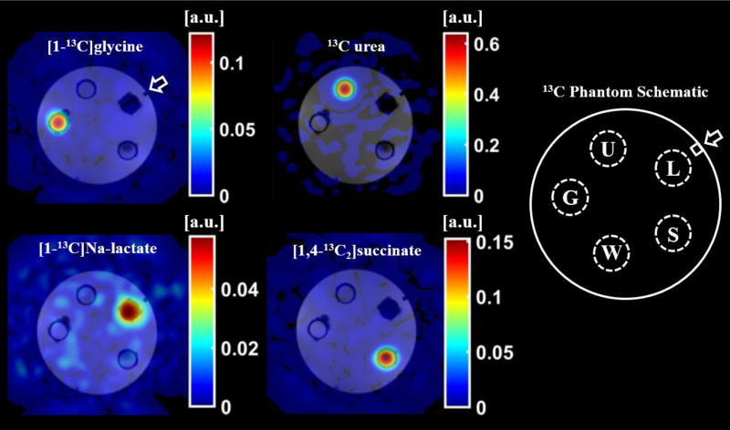
Figure 4 demonstrates an application of the phantom to validate a multi-spectral image acquisition and reconstruction method using four, thermally polarized 13C-labeled species: [1-13C]glycine, 13C-urea, [1-13C]Na-L-lactate, and [1,4-13C2]succinic acid. Image data acquired at the resonant frequency of 13C-urea was reconstructed using a least-squares, iterative reconstruction to separate the species and generate the individual panels of Figure 4. This data was collected using a larger version of this phantom (diameter = 48 mm). The design files for this larger phantom are included in the provided download page.
Figure 4.
A 2D, spoiled gradient-echo spiral sequence was acquired at the resonant frequency of 13C-urea and reconstructed using a least-squares, iterative reconstruction to produce images of the thermally polarized species [1-13C]glycine (G), 13C-urea (U), [1-13C]Na-L-lactate (L), and [1,4-13C2]succinic acid (S). The 13C species images (color) are overlaid on 1H, T1-weighted spoiled-gradient-echo images (grayscale) of the phantom filled with reverse osmosis purified water (W). The orientation marker (arrow) is clearly identifiable in the 1H, T1-weighted images.
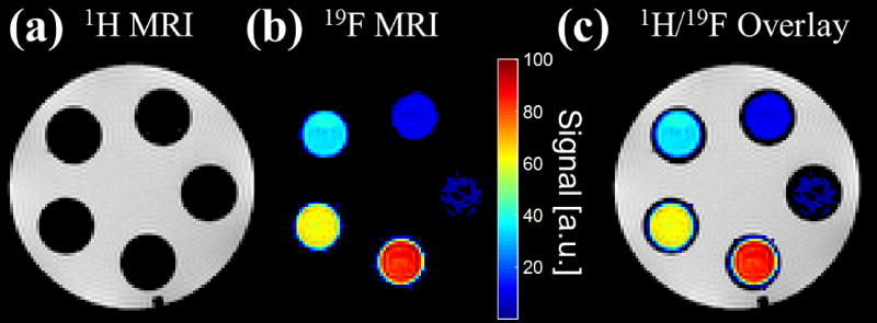
Finally, the phantom is capable of being used as both an alignment tool for 1H localization as well as 1H-to-19F MR images as demonstrated in the five different vials filled with pure concentrations of 19F species in Figure 5. Flood-filling the phantom with water clearly shows the location of the vials in Figure 5(a). After image reconstruction of the 19F data, shown in Figure 5(b), we can see the overlay of the 19F and 1H MR images aligning correctly, void of chemical shift artifact (Figure 5(c)).
Figure 5.
Two separate 3D, multi-echo, spoiled gradient-echo sequences were acquired on five vials with mixed relative volumes of 19F contrast agents: perfluoro-15-crown-5-ether (PFCE) and isoflurane. The first acquisition, with carrier frequency equal to the 1H resonant frequency, shows the 1H MR image of the water-filled phantom (a). The second acquisition, with carrier frequency equal to the 19F resonant frequency, shows the 19F MR image of only the PFCE contrast agent within the vials after reconstruction with a chemical shift encoded approach (b). The 1H and 19F MR images are easily superimposable (c).
4. Discussion
In this work, a preclinical MR phantom was designed and tested for the quantitative comparison of a set of contrast agent solutions. To the best of the authors’ knowledge, this MRI phantom uniquely represents a cost-effective 3D printable approach made available as open source. The most important practical feature of the phantom is that it enables a reproducible setup using low-cost commercially available micro-centrifuge tubes. Such an approach is particularly useful in the pre-clinical setting where coil dimensions and characteristics specific to a given application require specialized design solutions. A simple phantom with minimal size and magnetic field inhomogeneity due to susceptibility was desired for quantitative solution comparisons. Moreover, compatibility of the design with commercial micro-centrifuge tubes enables switching of solutions to compare, for example, different chemical formulations or concentration standards, as a researcher is able to maintain several sets of test solutions.
This proof-of-concept work demonstrates the phantom is capable of flood-filling. It is designed with an air hole for even solution filling and a fitting for use with a syringe. The flood filling can be used to create a load that is similar to that of in vivo studies of small animals while minimizing field inhomogeneity due to magnetic susceptibility at air interfaces and enabling B0 field correction for improved quantitative measures. Further, a vertical orientation marker runs the length of the phantom observable in axial slice orientation when in flood-filled mode for reproducible sample alignment and tracking. The orientation marker enables re-alignment of the phantom precisely between setups. For similar reasons, the phantom is also useful for optimizing different pulse sequences in a controlled setting to improve signal to noise and mitigate image artifacts.
The phantom presented here represents an inexpensive and useful option for a preclinical research group looking for a method for quantitatively comparing solutions of different concentration in a small animal MR system, as well as to assess image acquisition and reconstruction performance, and to validate image alignment and geometry. Quantitative determination of B0 field inhomogeneity and relaxation parameters of a Gd-based MR agent was demonstrated as a test of feasibility, but the phantom has general applicability for contrast agents’ development or applications requiring reference standards. It should be noted that the relaxivities calculated here differ slightly from those calculated by Rohrer et al in 2005 likely due to the differences in operating temperatures as well as the use of tap water in our setup. Recently, the phantom was used for chemical shift encoded data acquisition and image reconstruction optimization in both 19F (Ludwig et al 2017) and 13C (data unpublished) MRI. The flood-filled region of the phantom enables 1H shimming and localization procedures for vials with pure concentrations of 19F species, void of 1H signal.
The designs for this phantom have been made open-source. All design files, including the CAD design files of the components themselves, the 3D printing files for the two 3D printed parts and the laser cutting files for the two laser cut parts are all available for download. The design of the phantoms presented here was made to fit specific coils and sample vials. However, the CAD files can be easily modified to fit the individual needs of any research facility that may have more or less physical space within their coil and imaging system. This was demonstrated in the creation of a larger version of this phantom (designs also available), used for the collection of the data shown in Figure 4. A coil with a larger bore (50 mm) was used during the collection of this data allowing for a larger phantom to be built.
The increase in accessibility of 3D printing tools is improving quality, flexibility and access to common research tools at reduced cost. CAD software packages allow for design flexibility and 3D printing allows for flexibility of material choice, all depending on user preference and research need. For example, the physical size of the imaging RF coils used for this work limited the size of the phantoms and number of tubes that could fit, but these constraints were easily accommodated within the design files. As 3D printing tools continue to become more widely available, continued development of open-source tools promise to reduce cost and improve performance for basic imaging research applications.
5. Conclusion
An inexpensive and efficient phantom for the comparison of solutions in preclinical MR experiments has been designed and fabricated. The phantom is capable of flood-filling, allowing imaging of the samples of interest in water. Some of the applications of this device were demonstrated, with and without flood filling, using a series of Gd-doped solutions for B0 field mapping as well as the generation of T1 and T2 relaxation maps. Multi-spectral imaging and image alignment of 13C and 19F tubes was also demonstrated. The files necessary to recreate two versions of this phantom are made open-source and are available for download. This device is easy to use and can aid in preclinical studies for a variety of applications.
Acknowledgments
The authors thank Beth Rauch and the UW-Madison Department of Medical Physics for core scan time to allow methods development. This work is supported in part by the Morgridge Institute for Research, University of Wisconsin Institute for Clinical and Translation Research’s (UW ICTR) National Institutes of Health (NIH) awards UL1TR000427 and TL1TR000429, University of Wisconsin-Madison Radiological Sciences Training Grant, National Institutes of Health, National Cancer Institute award: T32CA009206, Hyundai Hope On Wheels award 133-AAB3113, as well as GE Healthcare.
Footnotes
The authors have no relevant conflicts of interest to disclose.
References
- Anderson JR, Diaz O, Klucznik R, Zhang YJ, Britz GW, Grossman RG, Lv N, Huang Q, Karmonik C. Validation of computational fluid dynamics methods with anatomically exact, 3D printed MRI phantoms and 4D pcMRI. Conf. Proc. Annu. Int. Conf. IEEE Eng. Med. Biol. Soc. 2014;2014:6699–701. doi: 10.1109/EMBC.2014.6945165. [DOI] [PubMed] [Google Scholar]
- Bieniosek MF, Lee BJ, Levin CS. Technical Note: Characterization of custom 3D printed multimodality imaging phantoms. Med. Phys. 2015;42:5913–8. doi: 10.1118/1.4930803. [DOI] [PMC free article] [PubMed] [Google Scholar]
- Chen SJ-S, Hellier P, Marchal M, Gauvrit J-Y, Carpentier R, Morandi X, Collins DL. An anthropomorphic polyvinyl alcohol brain phantom based on Colin27 for use in multimodal imaging. Med. Phys. 2012;39:554–61. doi: 10.1118/1.3673069. [DOI] [PubMed] [Google Scholar]
- Gallas RR, Hünemohr N, Runz A, Niebuhr NI, Jäkel O, Greilich S. An anthropomorphic multimodality (CT/MRI) head phantom prototype for end-to-end tests in ion radiotherapy. Z. Med. Phys. 2015;25:391–9. doi: 10.1016/j.zemedi.2015.05.003. [DOI] [PubMed] [Google Scholar]
- Ghiglia DC, Pritt MD. Two-dimensional phase unwrapping: theory, algorithms, and software. Wiley; 1998. [Google Scholar]
- Goldstein RM, Zebker HA, Werner CL. Satellite radar interferometry: Two-dimensional phase unwrapping. Radio Sci. 1988;23:713–20. [Google Scholar]
- Harrysson OLA, Hosni YA, Nayfeh JF. Custom-designed orthopedic implants evaluated using finite element analysis of patient-specific computed tomography data: femoral-component case study. BMC Musculoskelet. Disord. 2007;8:91. doi: 10.1186/1471-2474-8-91. [DOI] [PMC free article] [PubMed] [Google Scholar]
- Hazeveld A, Huddleston Slater JJR, Ren Y. Accuracy and reproducibility of dental replica models reconstructed by different rapid prototyping techniques. Am. J. Orthod. Dentofac. Orthop. 2014;145:108–15. doi: 10.1016/j.ajodo.2013.05.011. [DOI] [PubMed] [Google Scholar]
- Kasten JA, Vetterli T, Lazeyras F, Van De Ville D. 3D-printed Shepp-Logan phantom as a real-world benchmark for MRI. Magn. Reson. Med. 2016;75:287–94. doi: 10.1002/mrm.25593. [DOI] [PubMed] [Google Scholar]
- Khan AF, Drozd JJ, Moreland RK, Ta RM, Borrie MJ, Bartha R Alzheimer’s Disease Neuroimaging Initiative. A novel MRI-compatible brain ventricle phantom for validation of segmentation and volumetry methods. J. Magn. Reson. Imaging. 2012;36:476–82. doi: 10.1002/jmri.23612. [DOI] [PubMed] [Google Scholar]
- Kim MS, Hansgen AR, Wink O, Quaife RA, Carroll JD. Rapid prototyping: a new tool in understanding and treating structural heart disease. Circulation. 2008;117:2388–94. doi: 10.1161/CIRCULATIONAHA.107.740977. [DOI] [PubMed] [Google Scholar]
- Lazebnik M, Madsen EL, Frank GR, Hagness SC. Tissue-mimicking phantom materials for narrowband and ultrawideband microwave applications. Phys. Med. Biol. 2005;50:4245–58. doi: 10.1088/0031-9155/50/18/001. [DOI] [PubMed] [Google Scholar]
- Ludwig KD, Hernando D, Roberts NT, van Heeswijk RB, Fain SB. A chemical shift encoding (CSE) approach for spectral selection in fluorine-19 MRI. Magn. Reson. Med. 2017 doi: 10.1002/mrm.26874. [DOI] [PMC free article] [PubMed] [Google Scholar]
- Mashal A, Gao F, Hagness SC. Heterogeneous Anthropomorphic Phantoms with Realistic Dielectric Properties for Microwave Breast Imaging Experiments. Microw. Opt. Technol. Lett. 2011;53:1896–902. doi: 10.1002/mop.26128. [DOI] [PMC free article] [PubMed] [Google Scholar]
- Mitsouras D, Liacouras P, Imanzadeh A, Giannopoulos AA, Cai T, Kumamaru KK, George E, Wake N, Caterson EJ, Pomahac B, Ho VB, Grant GT, Rybicki FJ. Medical 3D Printing for the Radiologist. RadioGraphics. 2015;35:1965–88. doi: 10.1148/rg.2015140320. [DOI] [PMC free article] [PubMed] [Google Scholar]
- Moon SY, Hornak JP. A volume resolution phantom for MRI. Magn. Reson. Imaging. 2010;28:286–9. doi: 10.1016/j.mri.2009.07.002. [DOI] [PubMed] [Google Scholar]
- Nayak KS, Nishimura DG. Automatic field map generation and off-resonance correction for projection reconstruction imaging. Magn. Reson. Med. 2000;43:151–4. doi: 10.1002/(sici)1522-2594(200001)43:1<151::aid-mrm19>3.0.co;2-k. [DOI] [PubMed] [Google Scholar]
- O’Callaghan J, Wells J, Richardson S, Holmes H, Yu Y, Walker-Samuel S, Siow B, Lythgoe MF. Is Your System Calibrated? MRI Gradient System Calibration for Pre-Clinical, High-Resolution Imaging. PLOS ONE. 2014;9:e96568. doi: 10.1371/journal.pone.0096568. [DOI] [PMC free article] [PubMed] [Google Scholar]
- Reeder SB, Brittain JH, Grist TM, Yen Y-F. Least-squares chemical shift separation for (13)C metabolic imaging. J. Magn. Reson. Imaging. 2007;26:1145–52. doi: 10.1002/jmri.21089. [DOI] [PubMed] [Google Scholar]
- Rohrer M, Bauer H, Mintorovitch J, Requardt M, Weinmann H-J. Comparison of magnetic properties of MRI contrast media solutions at different magnetic field strengths. Invest. Radiol. 2005;40:715–24. doi: 10.1097/01.rli.0000184756.66360.d3. [DOI] [PubMed] [Google Scholar]
- Shmueli K, Thomas DL, Ordidge RJ. Design, construction and evaluation of an anthropomorphic head phantom with realistic susceptibility artifacts. J. Magn. Reson. Imaging. 2007;26:202–7. doi: 10.1002/jmri.20993. [DOI] [PubMed] [Google Scholar]
- Sodian R, Schmauss D, Markert M, Weber S, Nikolaou K, Haeberle S, Vogt F, Vicol C, Lueth T, Reichart B, Schmitz C. Three-dimensional printing creates models for surgical planning of aortic valve replacement after previous coronary bypass grafting. Ann. Thorac. Surg. 2008;85:2105–8. doi: 10.1016/j.athoracsur.2007.12.033. [DOI] [PubMed] [Google Scholar]
- Wurm G, Tomancok B, Pogady P, Holl K, Trenkler J. Cerebrovascular stereolithographic biomodeling for aneurysm surgery. Technical note. J. Neurosurg. 2004;100:139–45. doi: 10.3171/jns.2004.100.1.0139. [DOI] [PubMed] [Google Scholar]
- Yoshimaru E, Totenhagen J, Alexander GE, Trouard TP. Design, manufacture, and analysis of customized phantoms for enhanced quality control in small animal MRI systems. Magn. Reson. Med. 2014;71:880–4. doi: 10.1002/mrm.24678. [DOI] [PMC free article] [PubMed] [Google Scholar]


