

Abstract
Objective
The success of a cortical prosthetic device relies upon its ability to attain resolvable spikes from many neurons in particular neural networks over long periods of time. Traditionally, lifetimes of neural recordings are greatly limited by the body’s immune response against the foreign implant which causes neuronal death and glial scarring. This immune reaction is posited to be exacerbated by micromotion between the implant, which is often rigid, and the surrounding, soft brain tissue and attenuates the quality of recordings over time.
Approach
In an attempt to minimize the foreign body response to a penetrating neural array that records from multiple brain regions, Parylene C, a flexible, biocompatible polymer was used as the substrate material for a functional, proof-of-concept neural array with a reduced elastic modulus. This probe array was designed and fabricated to have 64 electrodes positioned to match the anatomy of the rat hippocampus and allow for simultaneous recordings between two cell-body layers of interest. A dissolvable brace was used for deep-brain penetration of the flexible array.
Main results
Arrays were electrochemically characterized at the benchtop, and a novel insertion technique that restricts acute insertion injury and enabled accurate target placement of four, bare, flexible arrays to greater than 4 mm deep into the rat brain. The array was tested acutely and in vivo recordings taken intra-operatively reveal spikes in both targeted regions of the hippocampus with spike amplitudes and noise levels similar to those recorded with microwires. Histological staining of a sham array implanted for one month reveals limited astrocytic scarring and neuronal death around the implant.
Significance
This work represents one of the first examples of a penetrating polymer probe array that records from individual neurons in structures that lie deep within the brain.
1. Introduction
Advanced cognitive functions of the brain, including that of memory, rely on effective communication between individual neurons within neural networks. These functional connections hold the key to understanding how the brain processes information. The hippocampus, a brain structure with a hierarchical network of intrinsic connections, is essential for the formation of new, long-term, declarative memories. Irreversible damage to the hippocampus, as occurs during the neurodegenerative physiological processes seen in Alzheimer’s disease, results in anterograde amnesia: the inability to form new memories in the future. Knowledge of the intricate workings of the neural circuitry of the hippocampus, and the ways in which the hippocampus malfunctions, has broad implications for neuroscience, medicine, and the field of brain-machine interfaces, specifically in the creation of hippocampal prosthetic devices [1]. In its ideal state, a hippocampal prosthesis could circumvent the point of injury and restore memory to patients with damage to their native biological circuitry.
Understanding the mechanism responsible for memory formation and the development of mathematical models that mimic the encoding and decoding processes of the hippocampus, requires recordings from individual neurons in the hippocampal network [2]. In addition, long-term, stable, unitary recordings from the hippocampal circuitry are fundamental for the understanding of long-term synaptic plasticity which is crucial for memory formation [3, 4]. The hippocampus is located in the medial temporal lobe with three subdivisions: the cornu ammonis (CA) 1, CA3, and dentate gyrus (DG). Hippocampal neurons lie compactly within a thin cell body layer that curves into a double-C shaped structure. Projections between these three regions, together with the entorhinal cortex (EC), form a trisynaptic circuit which is crucial in transforming short-term memories to lasting ones [5]. Simultaneous electrophysiological recordings from individual neurons in each hippocampal sub-region can provide knowledge of input-output characteristics of each of these regional contributors to memory formation.
Such data would ideally contain large numbers of unitary activities with high signal-to-noise ratios (SNR) monitored over long periods of time throughout the hippocampus. The most common design of current recording probes comprises thin, insulated metal microwires with exposed tips for recording. Arrays of multiple microwires have been configured to anatomically match hippocampal architecture, with longer wires used to target the deeper DG and CA3 structures, and shorter wires to target the more superficial CAI [6, 7]. However, this recording interface is not suitable for higher density recordings. These limitations have been overcome, in part, by microfabricated silicon-based neural probes, produced using standard micromachining techniques common to the semiconductor industry. Silicon-based probes can include dozens to hundreds of recording sites along the shank of each probe, allowing for recordings from multiple neurons along the length of the neural track [8]. With either approach, the spacing of shanks is ultimately limited by displacement of tissue and the severity of induced tissue trauma.
Despite the success of both silicon and microwire devices in animal and human subjects, a growing body of scientific research suggests the material composition of these devices is ill-suited for reliable, long-term recording applications. The high elastic moduli of silicon and metal (hundreds of GPa [9]) compared to the brain (∼10−6GPa) is frequently cited as a cause of tissue irritation and subsequent immune response. It has been posited that damage to the brain incurred by the micromotion of the rigid implants instigates tissue trauma in the form of local neuronal death and glial encapsulation around the implantation site [10–13], reducing recording quality or eliminating resolvable signals in as little as a few weeks [14, 15]. Although microdrives can maximize device lifetime by periodically advancing the probe to a new area of tissue to temporarily bypass fibrotic encapsulation, this approach precludes the ability to reliably target the same neurons chronically [16].
A potential design solution is to reduce the rigidity of the probe by replacing micromachined silicon with thin-film flexible polymers, such as polyimide, SU-8, or poly-(para-chloro-xylylene) (Parylene C) [17–19]. Recent work, including modeling, in vitro, and in vivo studies have found the use of compliant substrates mitigates inflammation and preserves neuronal density when compared to rigid materials [10, 11, 19–22]. By adapting micropatterning and micromachining techniques to polymer substrates, several iterations of polymer-based probes and arrays have been successfully deployed for acute and chronic recording applications in animal models [23–28]. However, polymer-based devices typically require specialized methods to implant into the brain without mechanical buckling [29] or undue tissue damage, and advances in polymer micromachining are needed to attain channel counts similar to silicon-based probes.
In pursuit of both high-quality, electrophysiological data from the hippocampus, and advances in polymer-based microprobe technology, we developed a flexible Parylene C neural probe array with 64 electrode sites that simultaneously targets two regions of interest in the hippocampus. The device comprises an array of eight, 5.5 mm long Parylene shanks supporting micropatterned platinum electrodes and electrical traces. In this paper, we discuss the design and fabrication of the polymer-based array and the application of a minimally invasive technique [30] to implant probes into deep-brain targets without mechanical buckling. Following electrical, electrochemical, and mechanical characterization of the probe array, we implanted devices into 4 rat hippocampi and obtained acute electrophysiological data. The quality of electrical recordings, including SNR, was compared to those from microwire electrode arrays. These quantitative comparisons are an expansion of initial recordings achieved during a single implantation that were preliminarily presented in [31, 32]. Additionally, the immune response against a sham array implanted for one month was evaluated through histological staining for the concentration of astrocytes and neurons near the implant. This characterization of the immune response against the implant over time build on preliminary histology results presented in [33].
2. Materialsand Methods
2.1 Design
The complete hippocampal recording setup includes a neural interface for collecting neural spikes and an electrical packaging system for transmitting these spikes to a recording system that can monitor and store spikes over time. The implanted neural probe array incorporates a ribbon cable that connects to a recording system during surgery. See Figure 1 for a schematic of the hippocampal recording setup.
Figure 1.

Overall schematic of hippocampal recording setup. Flexible neural probe array was inserted into the rat brain until it reached the regions of interest. Electrical traces leading away from the recording electrodes carry neural activities via printed circuit boards (PCBs) atop the rat’s cranium to an external recording instrument. Close-up of one of the eight probes in the electrode array illustrated to the right.
2.1.1 Electrode array
The eight shanks in each Parylene array were separated by 250 μm, spanning 2,000 μm of the dorsal hippocampus along the septal-temporal axis. The array was constructed from layered thin films of Parylene C (10-18 μm thick) and platinum (2000 Å thick). Parylene provides both structural support and electrical insulation. The sandwiched metal layer in each probe contained two groups of platinum electrodes and their traces. Parylene was chosen as a substrate due to its compatibility with micromachining processes, conformal deposition, United States Pharmacopeia (USP) class VI biocompatibility rating, and its flexibility. Pt was chosen to serve as the electrode material due to its biocompatibility, high electrical conductivity, and inertness in the body [34]. Since the deepest hippocampal layer of interest sits at a depth of 4-4.5 mm from the bregma (the cranial suture intersection landmark) on the surface of the skull, a probe length of 5.5 mm was used to reach all hippocampal regions of interest.
Principal neurons in the hippocampus pack into a cell body layer that is tens of microns thin and curves into a double-C structure that is functionally divided into the CAI, CA3 and DG sub-regions. In order for penetrating neural probes to record from each thin sub-region of the hippocampus simultaneously, electrode sites must be densely patterned along the length of each probe with some level of redundancy to overcome anatomical variations between animals. Therefore, each sub-region was targeted by a group of four linear electrodes which span the estimated thickness of each cell layer. This ensured that at least one electrode site resides in each targeted cell layer. The appropriate positions of electrode recording sites along the probe shanks were determined through a combination of rat brain atlas and histological measurements alongside in vivo recording tests (Figure 2) [35]. The exposed electrode area was 30 μm in diameter (electrode sites were patterned 50 μm in diameter and the edges were surrounded by insulation). Electrode diameters were chosen to improve their selectivity to individual neurons and limit their impact on the overall width of the shank, while balancing the need for sufficient surface area for reducing electrode impedance (<1 MΩ at a frequency of 1 kHz) and noise [36].
Figure 2.

Electrode positions were determined through a combination of rat atlas, histology, and recording data, (a) Atlas representation of hippocampal position within the rat brain and expanded view taken at different anterior to posterior locations (A-P), with a table indicating changes in the medio-loterol (M-L) positioning and separation distance between the CAI and CA3 layers, (b) Histological measurements of the distance between CAI and CA3 regions in three rats according to anterior-posterior and medio-loterol (AP-ML) coordinates with spacing between electrode groups in designed Parylene probe array superimposed in highlighted region, (c) Representative spikes from CAI and CA3 regions of the hippocampus, Recordings from microwire arrays indicated an average CAI to CA3 separation of 1.12 ± 0.33 mm.
The electrodes were connected to contact pads by 5 μm wide traces, with 5 μm spacing. This small trace width was chosen to decrease the overall width of each probe and thereby reduce the foreign body response to the implant. These design criteria enabled the realization of a probe whose width spans from 110 μm at its most tapered part, to 150 μm at its widest part. The shape and critical dimensions of the array and individual probes are presented in Figure 3.
Figure 3.

(a) Diagram of Paryiene neurai probe array with eight probes designed to match the anatomy of the hippocampus as the CAI and CA3 sub-regions change in depth along the septo-temporai axis. Two groups of four Pt electrodes (30 μm exposed diameter) target the CAI and CA3. (b) Shape and criticai dimensions of an individuai probe. *Thickness of insulative Parylene layer varies between 10, 14, and 18 μm.
2.1.2 Array implantation strategy
In order to implant electrodes in the hippocampus the supporting polymer probes must be longei than those of the majority of devices described in prior efforts which are typically only 1-3 mm long. This is in part because of a known challenge in inserting polymer probes into the brain; long, thin, flexible shanks will mechanically buckle under very small loads, deforming the probes during insertion. The force that induces buckling can be estimated from eq. 1 by modeling an individual probe as a mechanical beam of width w, thickness t, length L, and Young’s modulus E. This model assumes one end to be clamped to the insertion tool and the other pinned in the x-y plane as soon as it contacts brain tissue. For a Parylene C based neural probe array we would expect a single probe (20-28 μm thick, 110-150 Rm wide, 5.5 mm in length, with a Young’s modulus of 3.2 GPa) to certainly buckle at only 0.6 mN (for a probe modeled as a beam that is uniformly 28 μm thick and 150 μm wide). The insertion force required to penetrate brain tissue, however, is commonly accepted to be 1 mN [37].
| (eq. 1) |
This obstacle has traditionally restricted the application of flexible probes to superficial, cortica targets that are < 3 mm deep [23, 38, 39], as shorter probes have a higher buckling force threshold and may be inserted without buckling. Bulky insertion shuttles or dissolvable overcoats have been used with success to temporarily stiffen probes [19], but at the cost of increasing cross-sectional area and therefore acute insertion trauma.
In order to effectively stiffen our probe array, without resorting to rigid materials or increasing the cross-sectional footprint, we designed a temporary brace to reduce the effective length of the probe during insertion. By halving the length L, Fbucklingis increased four-fold to 2.3 mN (estimated), and by using a dissolvable material, the brace can be removed before inserting the remaining length of the probes into the brain. This dissolvable brace was fabricated from polyethylene glycol (PEG) and validated in mechanical tests before it was used in surgical implantations.
2.1.3 System packaging
Individual probes of the hippocampal array connected into a flat, flexible cable which terminate in Pt contact pads mated to a 71 pin zero-insertion-force (ZIF) connector (Hirose Electric Co., Japan). The ZIF used in this work had a space-saving double row design with a 200 μm pitch between contact pad: and a total length of 1.58 cm, which is less than the 2 cm anterior-to-posterior space available on the rat’s cranium.
The electrical packaging used during in vitro electrochemical testing consisted of a single PCB that served as an adapter between a ZIF and two 0.1″ spacing header boards, whose pins were easily connected to the working electrode of the potentiostat. Both cyclic voltammetry cleaning and electrode impedance spectroscopy were run on each of the 64 individual electrodes using this setup.
The electrical packaging for in vivo testing consisted of two, mated printed circuit boards (PCB), as depicted in Figure 1. The first PCB was permanently mounted to the rat’s head with dental cement, and supported the ZIF connector and an SSB6 PCB to PCB receptacle connector (Molex Incorporated, Lisle, IL). The second PCB was detachable, and supported a male SSB6 connector and two 32 position dual row nano-miniature Omnetics connectors (Omnetics Connector Corporation, Minneapolis, MN). The second PCB was connected during surgery and established connection from the electrical packaging to a differential amplifier and oscilloscope. This design was chosen to minimize the size of the permanent headmount.
2.2 Fabrication and assembly
2.2.1 Fabrication of Parylene array
A base layer of 10 μm thick Parylene C (Specialty Coating Systems, Indianapolis, IN) was deposited via chemical vapor deposition (CVD) onto a dehydrated, prime 4″ silicon wafer. AZ5214 (Integrated Micro Materials, Argyle, TX) image-reversal photoresist (step 1: 8 s, 500 rpm, step 2: 45 s, 2,000 rpm) was patterned via photolithography to define the electrodes and leads. The wafer was cleaned in O2 plasma, and 2000 Å platinum (Pt) was deposited by either sputter coating (LGA Thin Films, Santa Clara, CA) or electron beam evaporation (Caltech Kavli Nanoscience Institute, Pasadena, CA). The Pt features were defined by lift-off in acetone (50 °C) accompanied by gentle brushing. An insulation layer of Parylene, 10, 14, or 18 μm thick was subsequently deposited via chemical vapor deposition. A 15 μm thick layer of AZ4620 photoresist (Integrated Micro Materials, Argyle, TX) was spun (step 1: 5 s, 500 rpm, step 2: 45 s, 1,200 rpm) and patterned to produce an etch mask, and the array shape was defined using a switched chemistry process in a deep reactive ion etching tool that alternated between fluoropolymer deposition (C4F8) and oxygen plasma etching [40]. This first etch mask was removed in acetone, and a second mask of AZ4620 subsequently deposited 30 μm thick (two spins separated by softbake; step 1: 8 s, 500 rpm and step 2: 45 s, 2,000 rpm). In a second etch, the electrodes were exposed and the device fully defined by etching through the remaining layer of Parylene. Finally, the resist mask was stripped, the wafer rinsed sequentially with acetone, isopropanol and deionized water, and devices were released by gently peeling the device away from the native oxide layer of the silicon substrate while immersed in water. Any remaining photoresist was removed by soaking released devices for 5 minutes in baths of acetone, isopropanol, and water. Cleaned devices were sandwiched between Teflon and thermally annealed for 48 hours at 200 °C in a nitrogen purged oven under vacuum to reinforce adhesion between the layers of the device. Parylene contact pads were supported with 0.002″ thick polyether ether ketone (PEEK) tape with a 2.3 mil thick acrylic adhesive (CS Hyde Co., Lake Villa, IL) which enabled insertion into the ZIF connector for electrical packaging. Figure 4 contains photographs of a fully fabricated hippocampal array.
Figure 4.

(a) Photograph of fabricated array highlighting the neural interface (consisting of electrodes patterned onto probe shanks), Parylene ribbon cable, and contact pads which provide contact to the electrical packaging system, (b) Close-up of electrodes and traces.
2.2.2 Application of PEG brace onto arrays
In preparation for in vivo implantation, hippocampal arrays were partially encapsulated in a biodegradable PEG brace. This shortened the effective shank length by 4.55 mm, leaving only 0.95 mm of unexposed length and enabling probe insertion without buckling. The brace was created by casting molten PEG around the completed Parylene array using a mold prepared from three layers of 0.5 mm thick polydimethylsiloxane (PDMS) and assembled as depicted in Figure 5. The first PDMS layer serves as the base of the mold. The second and third layers sandwich the array, supported by an acrylic backing, and outlined a cavity which defines the thickness and shape of the brace. The hippocampal array contained within the PDMS assembly was heated in a 50 °C oven for 30 seconds. Molten PEG of molecular weight 3,350 (Sigma-Aldrich, Darmstadt, Germany) was injected into the cavity and a PDMS coverslip was placed on top to wipe away excess PEG. The entire assembly was then cooled at room temperature for 5 minutes until the PEG solidified. The encapsulated device was then removed from the mold carefully, using a pair of tweezers.
Figure 5.

PDMS mold used to create the PEG brace that supports probe shanks during implantation, The mold was comprised of three PDMS sheets: a base layer, a second layer which accommodates a clear acrylic insertion backing that supports the array as its probes span the mold cavity, and a third layer which is gently aligned to and laid over the probe tips to complete the mold, Molten PEG was injected into the mold cavity to brace the top length of the probes temporarily during implantation to allow for probe insertion into brain without buckling, (a) Photograph of PDMS assembly surrounding array with the mold cavity outlined by dotted red line, (b) Exploded view of PDMS layers and array on top of clear acrylic backing.
2.2.3 Preimplantation preparation of electronics
Braced arrays were attached to the electrical packaging via the ZIF connector. For the first implantation, a stainless steel microwire was manually connected to each Omnetics connector and placed in contact with rat cerebrospinal fluid for grounding. In all subsequent implantations, stainless steel ground wires that entered the brain were directly soldered to stability pads on the ZIF connector (Figure 6).
Figure 6.

Photograph of packaged electrical assembly, Ground wires directly soldered to ZIF connector of PCB 1.
2.3 Experimental procedures
2.3.1 Electrochemical cleaning and evaluation of electrode quality
Prior to PEG encapsulation and insertion into the ZIF, hippocampal arrays were potentiostatically cleaned using cyclic voltammetry (CV) [41] and analyzed using electrochemical impedance spectroscopy (EIS). CV (−0.2 V to 1.2 V, scan rate of 250 mVs−1) was run on each individual electrode trace for 30 cycles in 0.5 M H2SO4 purged with N2 for five minutes prior to scanning. A 1 cm2 Pt plate was used as a counter electrode and an Ag/AgCl electrode was used as a reference electrode. EIS was performed in 1× phosphate buffered saline (PBS) (OmniPur 10× PBS, EMD Chemicals, Darmstadt, Germany) with an excitation voltage of 25 mV (AC) over frequencies from 1 Hz to 0.1 MHz. Electrodes with impedance measuring greater than 2 MΩ at 1kHz, or with a phase spectrum that did not transition from resistive (close to 0°) to capacitive (close to −90°) with decreasing frequency, were considered open circuits and were not used for average impedance calculations.
2.3.2 Implantation procedure
Both the Institutional Animal Care and Use Committee (IACUC) and the Department of Animal Resources of the University of Southern California (DAR, USC) reviewed and approved of all animal experiments. Four fully functional arrays that passed electrochemical testing were implanted into four male, Sprague-Dawley rats older than 3 months of age and weighing between 300-450 g. Animals were pre-anesthetized with an intraperitoneal (IP) injection of a ketamine and xylazine mixture. Anesthesia was maintained intra-operatively through the delivery of an inhaled mixture of isoflurane and oxygen delivered to the animal. Negative toe pinch withdrawal reflexes tested throughout surgery confirmed appropriate anesthetic level. A stereotactic frame was used to hold the animal in place. To expose the brain surface above the implantation site, a 2 × 4 mm cranial window was drilled away above the right dorsal hippocampus and the dura was carefully removed with forceps. Three small holes, for anchor screws, were drilled in the skull surrounding cranial window. One anchor screw doubled as a ground, by making contact with the cerebrospinal fluid. A small hole for the ground wire itself was drilled above the cerebellum. Arrays were connected to an oscilloscope through the in vivo electrical packaging system during insertions.
The exposed, bare tips of a hippocampal array were poised above the implantation site located at ∼2.5 mm posterior to bregma and ∼2.45 mm left of the midline. A micromanipulator was used to support and advance the array during implantation. The array was angled ∼30° from the midline in order to align to the septal-temporal axis of the hippocampus. The array was slowly inserted into the brain until the bottom edge of the PEG brace reached the surface of the brain. The brace was then gradually dissolved away with saline solution and the newly exposed array length was advanced in increments of 0.05 mm at a speed of 10 μm/s. If the PEG brace was directly submerged in saline, it would take < 20 min to fully dissolve. During the insertion advancement of the array was frequently paused to monitor neural activities at each depth. Therefore, the dissolution of the PEG brace was carefully controlled to avoid unnecessary array exposure during the surgical pauses. To accomplish this, a small amount of saline was applied directly to the part of the PEG brace to be dissolved and any excess saline was blotted away. Neural signals were monitored throughout the implantation procedure for the presence of complex spikes (a burst of 2-6 single spikes of decreasing amplitude with ≤ 5 ms interspike intervals [42]). Complex spikes serve as an electronic signature for pyramidal neurons of the hippocampus and helped to confirm proper placement of the array in both the CAI and CA3 layers of the hippocampus. Once the first group of electrodes began recording spikes from the more superficial, CAI layer of the hippocampus (located at ∼3 mm deep from the surface of the skull), the array was further advanced until the second group of electrodes reached the CAI, at which point the first group of electrodes recorded from the deeper, CA3 layer.
After the array had reached the desired target location, a thin layer of dental cement was applied over the insertion site to hold the array in place. The ground wire was twisted onto the screw that acted as the ground electrode for added stability, and the tip of the ground wire was inserted into the hole above the cerebellum. The electrical packaging was lowered to the cranium and additional dental cement was then applied to create a ‘cap’ of dental cement that encapsulated the array and the first half of the permanent PCB, with care taken to leave the SSB6 receptacle at the top of the PCB exposed for future PCB to PCB connections during experiments.
2.3.3 Data Acquisition
During array implantation, recorded signals were bandpass filtered between 300-3000 Hz using an alternating current differential amplifier and displayed on an oscilloscope. The oscilloscope output was connected to a speaker to allow for auditory discrimination between single spike and complex spike activity. Spikes from electrodes in the CAI and CA3 electrode groups were collected in one second long recording traces for signal to noise ratio analysis.
2.3.4 Histological analysis of immune response after one month
A sham array, which lacked metal electrodes and traces, but was otherwise identical to fully fabricated arrays, was implanted into the right hippocampus of a single rat. This animal was sacrificed at one month post-implantation, at which time the animal was deeply anesthetized with an IP injection of ketamine and xylazine and intracardially perfused with 10% paraformaldehyde. The rat brain was dissected from the cranium and the hippocampal array was removed from the brain. After the brain was dehydrated in 18% sucrose overnight, the tissue was then embedded in 3% agarose for slicing. 50 μm thick transverse slices cut with a vibratome (Lecia, VT1000 S). Slices taken at a depth of 2.7 mm and 2.75 mm were stained with antibodies for glial fibrillary acidic protein (GFAP) and neuronal nuclei (NeuN) respectively for the identification of astrocytes and neurons and counterstained with hematoxylin. Sections of tissue on the same histological slice, on the same hemisphere, but > 500 μm away from the implant site were chosen as control regions for comparison. Radial rings of 25 μm were drawn around probe cross-sections and corresponding control regions. Color thresholding in ImageJ software (National Institutes of Health, Bethesda, MD) was used to identify and count the concentration of astrocytes in each annulus. Rectangular bins of 50 μm width, whose length matched the thickness of the cell body layer were used to count the concentration of neurons in implanted and control regions.
3. Results
3.1 In vitro cyclic voltammetry cleaning and electrode impedance spectroscopy
CV cleaning of electrodes successfully removed residual scum left over from processing from the surface of the electrodes, as evidenced by higher magnitude currents (lower impedances) in each of the 30 consecutive CV cycles. Residual photoresist, redeposited material during plasma etching of Parylene over the electrode site, or solvent evaporation during electrode cleaning can leave leftover organic debris on the electrode surface. Electrochemical impedance, measured at 1 kHz, decreased 37% (n=8) from a mean of 801 ± 29 kΩ to 507 ± 60 kΩ following CV cleaning. In a larger survey of electrodes (n=256 electrodes across four arrays) the mean electrochemical impedance of clean electrodes at 1 kHz was calculated as 677 ± 297 kΩ.
3.2 Neural recordings during implantation
Critical data describing the four implantations, and representative data describing subsequent neural recordings, are compiled below in Table 1 and Figure 6. During implantation of the probe, neural signals were monitored by oscilloscope, which allowed for observation of just a single electrode at a time. We considered each cluster of four closely spaced electrodes to be a ‘recording group’, and collected data from a representative electrode from each group throughout implantation. Recording groups containing at least two electrodes that passed electrochemical inspection prior to implantation were considered functional electrode groups. A total of 57 (out of 64) recording groups were considered functional and were monitored during four implantation surgeries. Unitary activities and complex spikes were successfully recorded from 35 recording groups (61.4% of functional recording groups).
Table 1.
Implantation coordinates, final target placement, and number of functional probes across four array insertions.
| Implantation | X,Y implantation coordinates | Depth of CAI complex spikes | Depth of final placement | Number of functional probes that reached both CAI and CA3 |
|---|---|---|---|---|
| 1 | 2.64, 2.45 | −2.95 | −4.15 | 2 |
| 2 | 2.49, 2.45 | −2.91 | −4.10 | 5 |
| 3 | 2.43, 2.45 | −2.98 | −4.15 | 2 |
| 4 | 2.49, 2.45 | −2.50 | −4.10 | 4 |
In each of the four implantation surgeries, signals were obtained from electrodes in both the CAI and CA3 sub-regions. Probes with two or more working electrodes in both the CAI and CA3 electrode groups were considered functional probes. A total of 28 functional probes (out of 32) were implanted, and, at the final implant location, 13 of these shanks recorded unitary activities from both the CAI and CA3. As the insertion procedure progressed, the depth at which complex spikes from these two sub-regions were detectable was recorded. Implantation coordinates and final depth placement are listed in Table 1, along with the number of functional probes on each array that reached both target sites. Figure 7 shows representative spikes recorded with the hippocampal array. A representative comparison between complex spikes recorded with the Parylene array and a microwire array is shown in Figure 8.
Figure 7.

Complex spikes (burst of 2-6 single spikes of decreasing amplitude with ≤ 5 ms interspike intervals) recorded from the CAI and CA3 during the second implantation surgery, (a) 1 s long recording traces from electrodes on the same probe recording from both the CAI and CA3 once the array has reached its target location. (b) Zoom-in view showing complex spikes recorded from the same electrodes that, initially during implantation lay within the CAI sub-region, and, as the probe was advanced, eventually reached the CA3. Color coded anterior-posterior sections of the hippocampus illustrate the change in hippocampal depth along the anterior-posterior direction.
Figure 8.

Peak-valley spike amplitude and background noise of a representative recording from a previous microwire array implantation and compared to recordings achieved with the Parylene array.
3.3 Quality of in vivo recordings
Metrics for recording quality include average peak-to-valley spike amplitudes, background noise, and signal to noise ratio (SNR). SNR was calculated using the following formula:
where A, the mean amplitude of spikes, is the average of peak-to-valley voltage of waveforms in each 1 s trace. SDnoise is the standard deviation of the background noise. Each 1 s long recording trace was low pass filtered to remove baseline drift. Spikes were defined as peaks with negative amplitudes greater in magnitude than a threshold of two standard deviations of the filtered recording trace. After removing spikes from the trace (the removed segments include both 400 μs before and 1,200 μs after threshold crossing) the standard deviation of the baseline noise was calculated. The maximum SNR achieved by any electrode was 26.1. Figure 9 shows the mean peak-to-valley spike amplitudes and background noise levels across all working electrodes recorded during surgery, while Figure 10 displays the average SNR values achieved by each Parylene array. Each of these two figures contains a comparison to data recorded with conventional microwire arrays.
Figure 9.

Average spike amplitudes and noise levels (with standard deviations) across all four Parylene array Implantations (shaded light blue bars) compared to those from seven microwire array implantations (solid green bars). The maximum spike amplitude recorded for Parylene and microwire array implantations is noted by the circle above each bar which connects to the y-axis on the right with dashed lines.
Figure 10.

Average signal to noise ratio (with standard deviations) achieved by each Parylene array. Dashesd line represents the average signal to noise ratio across seven microwire array implantations.
3.4 Histological analysis of immune response at one month post implantation
The concentrations of astrocytes and neurons around the implantation site of a sham array, measured one month post implantation, are presented in Figure 11, Figure 12, Figure 13, Table 2, and Figure 14. Tissue slices were taken at a depth of 2.7 mm and 2.75 mm and stained for GFAP and NeuN respectively with hematoxylin counterstain. At 2.7 mm deep, the probes deviated slightly from the cell body layer, whereas at 2.75 mm the probes cleanly hit the cell body layer. Control regions were chosen to mimic the offset of each probe from the cell layer in order to control for the heterogeneity in cellular distribution. Radial rings of 25 μm were drawn around probe cross-sections and the corresponding control regions. Color thresholding was used to create a color mask which allowed for the calculation of the concentration of astrocytes. Rectangular annuli fit to the thickness of the cell body layer were used to calculate the concentration of neurons since neurons largely lie within the cell layer. The concentration of the cell of interest was defined to be the fraction of area in each ring occupied by the stain of interest.
Figure 11.
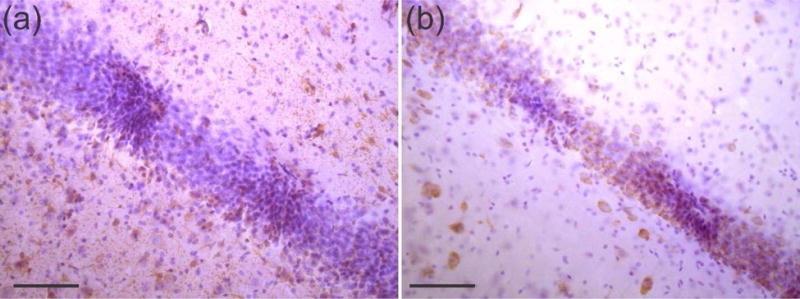
Close-up of immunohistolochemical staining of transverse, 50 μm thick hippocampal slices after sham array removal (a) stained with GFAP to highlight astrocytes surrounding probe implant sites in brown, taken at a depth of 2.7 mm, (b) stained with NeuN to highlight neurons in between probe implant sites, taken at a depth of 2.75 mm with purple corresponding to hematoxylin counter staining. Scale bars are 100 μm.
Figure 12.

Transverse, 50 μm thick hippocampal slice implanted with sham array that was stained with GFAP to highlight astrocytes in brown, taken at a depth of 2.7 mm. Purple corresponds to hematoxylin counter staining; dense purple strip is the DG of hippocampus. Array was removed prior to tissue slicing. (a) Black arrows indicate locations of five probes of the array visible in the DG of the hippocampus and (b) is the corresponding control area from the same tissue slice. (c & d) Color thresholding of (a) and (b), respectively, to measure astrocytic density in 25 μm rings around the central three probes and corresponding control regions, labelled A, B, and C. Zings reach 150 μm from probe cross-sections. Scale bars are 100 μm.
Figure 13.

Transverse, 50 μm thick slice of hippocampus implanted with sham array that was stained with NeuN to highlight neurons in brown, taken at 2.75 mm deep. Purple corresponds to hematoxylin counter staining; dense purple strip is the DG of the hippocampus. Array was removed prior to tissue slicing. (a) Black arrows indicate locations of five probes of the array visible in the DG of the hippocampus and (b) is the corresponding control area from the same tissue slice. (c & d) Color thresholding of (a) and (b), respectively, to measure density of neurons in 50 μm thick rectangles around the central three probes and corresponding control regions. Scale bars are 100 μm.
Table 2.
Density of astrocytes (area populated by astrocytes/area of ring) in rings arranged in 25 μm increments away from implanted and control regions. Average and standard deviation across three probes and control sites included.
| Radial distance (μm) | Probe A |
Control A |
Probe B |
Control B |
Probe C |
Control C |
Probe average | Control average |
|---|---|---|---|---|---|---|---|---|
| 25 | 20.7 | 3.0 | 14.3 | 2.1 | 4.7 | 0.4 | 13.2± 8.1 | 1.8± 1.3 |
| 50 | 14.8 | 6.4 | 9.9 | 2.0 | 7.7 | 0.1 | 10.8±3.6 | 2.8±3.2 |
| 75 | 15.7 | 9.4 | 14.5 | 2.0 | 14.3 | 1.5 | 14.8± 0.7 | 4.3±4.4 |
| 100 | 9.8 | 14.6 | 9.3 | 2.2 | 9.8 | 0.4 | 9.7±0.3 | 5.7±7.8 |
| 125 | 4.9 | 15.9 | 12.0 | 9.0 | 12.5 | 4.0 | 9.8±4.2 | 9.6±6.0 |
| 150 | 10.7 | 11.7 | 9.2 | 11.9 | 7.7 | 7.3 | 9.2± 1.5 | 10.3± 2.6 |
Figure 14.

Concentration of neurons in implanted and control rectangular bins. Green data points correspond to neuronal concentration in the bins surrounding the implant site. Non-solid circles correspond to the center of three probes in the array and naturally have the lowest concentration of neurons. Solid blue horizontal line represents the average neuronal concentration across all control bins; dashed lines and blue shaded region represent ± 1 standard deviation of the average concentration. Neuronal concentration returns to control levels in between probes in the array.
Figure 12 shows histology images of the implanted and control regions with astrocytes stained in brown with GFAP (first two panels). Panels (c) and (d) of Figure 12 have a superimposed color mask in red over regions populated by astrocytes. Astrocytes, a glial support cell in the brain, are known to increase in number around areas of injury and attempt to wall-off foreign implants through scar formation. An increase in astrocytic concentration around the implant site serves as an immune marker for the severity of the immune response against the individual probes in a neural array. An examination of these images reveals a small increase in astrocyte concentration at rings close to the implant site compared to control, non-implanted regions. The concentration of astrocytes in each radial ring surrounding three probes tracks, and the corresponding values from a control region, are presented in Table 2. On average, the concentration of astrocytes within 100 μm of the implanted locations was 8.5% ± 3.3% higher than their control counterparts and was shown to statistically differ between implanted and control regions (p < 0.05). However, no significant difference in astrocytic concentration beyond those in the control region was observed at distances greater than or equal to 100 μm from the probe track (p > 0.05).
A comparison of neuronal concentration (neurons were stained in brown with NeuN) is presented in Figure 13 and presented graphically in Figure 14, in order to evaluate whether or not neural death occurred near the implant site. Rectangular bins 50 μm wide whose lengths matched the varying thickness of the cell body layer were used to compare the concentration of neurons across the site of array implantation to a control region. A comparison between implanted and control sites reveals that neuronal concentrations return to normal in the ∼100 μm space between adjacent probes in the array.
4. Discussion and future work
4.1 Recording performance and immune reaction
The Parylene C arrays proved simple to handle and physically robust despite the mechanical flexibility of the base material. This is a favorable quality in a neural interface, considering the frustrating risk of fracture inherent to silicon probe arrays with similarly thin (20 μm) profiles. Despite the low elastic modulus of the Parylene structure, arrays were easy to implant with the addition of the PEG brace. Use of the dissolvable PEG brace prevented buckling or significant curving of the flexible probes during implantation and did not require introducing the brace material to the brain tissue. The success of this approach was confirmed through examination of histology data; minimal tissue was displaced due to insertion of the probes [30], unlike previously reported methods involving the use of large insertion shuttles [39, 43–46]. The use of a dissolvable brace has been described previously for thin metal microwire probes and carbon fiber probes [47] and our results confirm its efficacy for polymer-based neural probe arrays.
Electrochemical characterization confirmed the Pt electrodes exhibited adequately low impedance at 1 kHz (677 ± 297 kΩ), which corresponds well to that of commercially available stainless steel microwires (600-900 kΩ) with comparable electrode sizes (Parylene probe: 30 μm diameter, microwire: 25 μm diameter). These impedance values fall within the 50 kΩ – 1 MΩ range [36] required for the resolvable acquisition of neural recordings, and are largely determined by the exposed surface area of the Pt electrode site. The 30 μm diameter Pt electrodes were sufficiently small for the selective resolution of unitary activities and we obtained recordings from single neurons with spike amplitudes (139.3 ± 75.6 μV), noise levels (37.8 ± 6.5 μV) and SNRs (3.6 ± 1.4) similar to those of microwires deployed for hippocampal neural recordings in previous work. The observed variation in spike amplitude is attributable to variation in the distance between the recording site and adjacent neurons [48] and neuron size. The presence of high amplitude spikes indicate that the hippocampal array was implanted close to the cell body layer of interest.
The quality of this recording data was more than sufficient to fully resolve spike activites with high fidelity, and as such we believe will be suitable for acute and, ultimately, chronic applications studying hippocampal neural circuits in free moving subjects. The recorded neural data compares favorably both with commercial microwire probes and other microfabricated neural probe arrays. Due to differences in SNR calculations between research groups [49–51] a direct comparison between SNR measurements across literature is difficult. However, the SNR values of this hippocampal array is peppered with quality (SNR > 4:1) and moderate (3:1 < SNR < 4:1) units defined by the experimentally based measurements of Ludwig et. al. [50], and the values reported here are similar to prior work using silicon-based neural arrays to record from the hippocampus [48]. We also note that some noise was introduced by an unstable SSB6 connection between the two mated PCBs in the electrical packaging. In future work this connection will be removed entirely, and the SNR of the recording array may increase above that reported here.
The greatest advantages of this neural array, compared to other methods of recording hippocampal activity, are the high density of anatomically placed electrode sites (compared to microwires), and the mitigated immune response arising from the soft-polymer construction (compared to silicon-based arrays). Comparing the ratio of a single probe cross-sectional area to the number of electrode sites on that probe produces values of 707-962 μm2/electrode for microwires (Microprobes for Life Science, Gaithersburg, MD, 25 μm diameter, 2.5-5 μm insulation) compared to 275-525 μm2/electrode for the device presented here. Each Parylene probe would occupy less than half the volume of a microwire with the same number of recording sites, which displaces less tissue and may attenuate the immune response against the foreign implant [10].
The anatomically-matched design of the electrode layout enabled recording from both thin layers of the hippocampus simultaneously in all four subjects. Correct placement in both layers was confirmed through the electrophysiological detection of complex spikes, representative of hippocampal neural activity. Simultaneous multilayer recording is a key feature of the array, and required precise positioning of electrodes during the design of the probe and careful placement of the array during the implantation surgeries. Anatomical variations between rat subjects served as a potential obstacle, however recordings from both the CAI and CA3 layers in all four animals speaks to the success of the array design and efficacy of electrode redundancy. The similarity in the final depth of the four arrays could allow for future implantations to the target depth directly, rather than slowly monitoring intra-operative spike signals, reducing the complexity of surgical targeting.
An initial investigation into the foreign body response against the flexible, Parylene array was promising and indicated limited astrocytic scarring and neuronal death as compared to more rigid (silicon) implants. The analysis of transverse slices, stained with immunohistochemistry, of a hippocampus implanted with a sham hippocampal array for a single month proved to be challenging. Traditionally, when evaluating the immune response in the cortex, a transverse slice is binned into rings of increasing radii, and the increase in immune markers or decrease in neuronal population is clearly measured according to the distance away from the implant site since the tissue is homogeneous. However, in the hippocampus, neuronal cell bodies are restricted to the cell layer itself, and astrocytes add structural support to the tissue—and in the histological slices seen in Figure 12 and Figure 13, are distributed mainly in the inner area of the cell body layer. This complicates analysis of the immune response against the hippocampal array, since probes that have successfully penetrated through the cell layer itself will naturally be surrounded by greater populations of neurons and fewer astrocytes, and probes that have deviated from the cell layer will show the opposite trend. To minimize the impact of this heterogeneity on the histological analysis of the results, control regions for GFAP were chosen from the same slice, at a location > 500 μm away from the implant site, at comparable offsets from the cell layer. It is important to note, that for the hippocampal slice stained with GFAP, percent astrocyte measurements in each radial ring increase according to distance away from the probe, as rings located farther away include more of the astrocytes that hug the interior of the cell body layer. For the hippocampal slice stained with NeuN, rectangular bins were matched to the width of the cell layer in order to accurately calculate the change in concentration of neurons within the cell layer itself.
It appears that astrocytes lining the inner surface of the DG have been activated within the cell layer itself in an attempt to physically wall off the foreign implant from natural tissue. This type of immune reaction against an implanted neural probe is commonly documented and is believed to encapsulate the electrodes, electrically insulating them from surrounding neurons. This begins at 2-4 weeks post-implantation, with a chronic, glial scar of astrocytes that grows stable at 6-8 weeks post-implantation [52]. Death of nearby neurons occurs by 2 weeks post implantation [11]. While some astrocytic scarring and neuronal death surrounding the hippocampal shanks of this study are present, astrocytic concentration returns to normal at distances > 100 μm from the probe track and neuronal concentration returns to control levels in the ∼100 μm space between the edges of adjacent shanks. Histological studies that observe the four week histological response surrounding rigid silicon implants indicate a far greater disruption in neuronal density that only returns to normal within 50 [53] – 300 μm [11] from the implant surface and an increase in astrocytic concentration that can span beyond 500 μm [11] from the implant surface. Studies that have directly compared histological data between flexible and rigid probes uncover close to a two-fold improvement in astrocytic attenuation and neuronal density surrounding the flexible implants. A comparison of the immune response to silicon and softer nanocomposite probes implanted for 4 weeks found that neuronal densities return to normal at 200 μm from the rigid implant and at a distance of 100 μm for the flexible implant [22]. The histological data from our hippocampal array perhaps exceeds the results of this study in that neuronal density returns to normal within the 100 μm space between probe edges of adjacent probes. Flexible probes had twice the neuronal density of rigid ones in the first 50 μm away from the implant [21] and GFAP levels were almost half that of rigid probes up to 50 μm away from a flexible implant [54] though in this study no statistically significant difference in neuronal concentration was witnessed. Both of these two factors—astrocytic encapsulation of the neural probe and death of nearby neurons—are mechanisms that directly contribute to reduced signal quality over time. However, these immune trends continue to evolve over time as supported by this same study which observed no neuronal loss around the compliant implant at 16 weeks post-implantation [22]. This is a positive factor in predicting the continued chronic performance of the hippocampal arrays presented in this paper.
4.2 Future Directions
Future devices will be implanted in rat models and will be monitored chronically, until unitary activities are no longer visible, to determine the recording lifetime of our Parylene arrays and long-term SNR stability. Future modifications to the hippocampal array are underway and include improvements in fabrication, design of the electrical interface between the array and recording systems, and further histology staining and analysis to quantify the immune response against the flexible hippocampal array over time. Sputter deposited Pt was found to have a high compressive stress that caused array curling upon lift-off and the thickness of the insulation layer of Parylene was adjusted from 10 to 14 or 18 μm to attenuate this curvature. Future devices will use electron beam deposited Pt, so that the compressive stress of the system can be wholly overcome through a thermal annealing step while maintaining the Parylene insulation thickness at 10 μm, equal to the thickness of the Parylene base layer. Changes to the electrical packaging will eliminate the need for two PCBs, and will adapt directly from ZIF to Omnetics in a single PCB to eliminate the noise added to the system through the SSB6 connection while only increasing the footprint on the rat’s skull by a manageable 10%. Future immunohistochemical studies will stain for Cdllb, specific to microglia, the macrophages of the brain, in addition to the traditional GFAP and NeuN staining to expand understanding of the immune players. Tissue from the contralateral, native hippocampus will be used as a histological control to help account for variations in cell layer thickness.
5. Conclusion
Sortable complex spikes were successfully recorded from the CAI and CA3 layers of a rat hippocampus simultaneously using a Parylene-based neural probe array. The array featured eight electrodes on eight individual probe shanks, designed to match the variegated anatomy of the hippocampus for study of the trisynaptic hippocampal circuit. Average spike amplitudes (139.3 ± 75.6 μV), noise baselines (37.8 ± 6.5 μV), and SNR (3.6 ± 1.4) compare favorably with microwire and silicon probes implanted in hippocampal layers in terms of signal fidelity and sensitivity. Histological staining of tissue surrounding the implant at one month post-implantation reveals that astrocytic density increases near the insertion site (as compared to control), but returns to normal within 100 μm from the implant site. Neuronal density was observed to decrease in the immediate vicinity of implant sites, but returned to control levels in the ∼100 μm space between probes of the same Parylene array. Minimal damage to the neuronal tissue was observed in tissue slices at the one month mark. This data supports previous reports that thin-film flexible probes may mitigate immune response and tissue damage compared to neural implants made from stiffer materials.
This report describes one of the first examples of a polymer neural probe array recording unitary activities from deep brain structures a feat made possible from the use of a dissolvable brace to reduce probe buckling without the use of an insertion shuttle. The results bode well for the approach and have motivated continued work exploring the polymer array as a solution to the challenges facing chronic recording in deeper brain structures.
Acknowledgments
This work was sponsored by the NSF under award number CBET-1343193 and NIH under award number U01 NS099703. The authors would like to thank Dr. Donghai Zhu and members of the Center of Neural Engineering and the USC Biomedical Microsystems Laboratory for their assistance. Special thanks to Madeleine Combs for her patient assistance in the electrochemical cleaning and testing of arrays prior to implantations and to Young Ouk (Alex) Kim for his skillful soldering abilities.
References
- 1.Song D, Robinson B, Hampson R, Marmarelis V, Deadwyler S, Berger T. Sparse Large-Scale Nonlinear Dynamical Modeling of Human Hippocampus for Memory Prostheses. IEEE Transactions on Neural Systems and Rehabilitation Engineering. 2016 doi: 10.1109/TNSRE.2016.2604423. [DOI] [PMC free article] [PubMed] [Google Scholar]
- 2.Berger TW, Song D, Chan RH, Marmarelis VZ. The neurobiological basis of cognition: identification by multi-input, multioutput nonlinear dynamic modeling. Proceedings of the IEEE. 2010;98:356–374. doi: 10.1109/JPROC.2009.2038804. [DOI] [PMC free article] [PubMed] [Google Scholar]
- 3.Song D, Chan RH, Robinson BS, Marmarelis VZ, Opris I, Hampson RE, et al. Identification of functional synaptic plasticity from spiking activities using nonlinear dynamical modeling. Journal of neuroscience methods. 2015;244:123–135. doi: 10.1016/j.jneumeth.2014.09.023. [DOI] [PMC free article] [PubMed] [Google Scholar]
- 4.Robinson BS, Berger TW, Song D. Identification of stable spike-timing-dependent plasticity from spiking activity with generalized multilinear modeling. Neural computation. 2016 doi: 10.1162/NECO_a_00883. [DOI] [PubMed] [Google Scholar]
- 5.Andersen P. The Hippocampus Book. Oxford University Press; 2007. [Google Scholar]
- 6.Xu H, Hsiao M-C, Song D, Berger TW. Recording place cells from multiple sub-regions of the rat hippocampus with a customized micro-electrode array. 2014 36th Annual International Conference of the IEEE Engineering in Medicine and Biology Society. 2014:4876–4879. doi: 10.1109/EMBC.2014.6944716. [DOI] [PubMed] [Google Scholar]
- 7.Deadwyler SA, Bunn T, Hampson RE. Hippocampal ensemble activity during spatial delayed-nonmatch-to-sample performance in rats. Journal of Neuroscience. 1996;16:354–372. doi: 10.1523/JNEUROSCI.16-01-00354.1996. [DOI] [PMC free article] [PubMed] [Google Scholar]
- 8.Fekete Z. Recent advances in silicon-based neural microelectrodes and microsystems: a review. Sensors and Actuators B-Chemical. 2015 Aug;215:300–315. [Google Scholar]
- 9.Scholten K, Meng E. Materials for microfabricated implantable devices: a review. Lab on a Chip. 2015;15:4256–4272. doi: 10.1039/c5lc00809c. [DOI] [PubMed] [Google Scholar]
- 10.Kozai TD, Jaquins-Gerstl AS, Vazquez AL, Michael AC, Cui XT. Brain tissue responses to neural implants impact signal sensitivity and intervention strategies. ACS chemical neuroscience. 2015;6:48–67. doi: 10.1021/cn500256e. [DOI] [PMC free article] [PubMed] [Google Scholar]
- 11.Biran R, Martin DC, Tresco PA. Neuronal cell loss accompanies the brain tissue response to chronically implanted silicon microelectrode arrays. Experimental neurology. 2005;195:115–126. doi: 10.1016/j.expneurol.2005.04.020. [DOI] [PubMed] [Google Scholar]
- 12.Kozai TDY, Vazquez AL, Weaver CL, Kim S-G, Cui XT. In vivo two-photon microscopy reveals immediate microglial reaction to implantation of microelectrode through extension of processes. Journal of neural engineering. 2012;9:066001. doi: 10.1088/1741-2560/9/6/066001. [DOI] [PMC free article] [PubMed] [Google Scholar]
- 13.Chen R, Canales A, Anikeeva P. Neural recording and modulation technologies. Nature Reviews Materials. 2017;2:16093. doi: 10.1038/natrevmats.2016.93. [DOI] [PMC free article] [PubMed] [Google Scholar]
- 14.Williams JC, Rennaker RL, Kipke DR. Long-term neural recording characteristics of wire microelectrode arrays implanted in cerebral cortex. Brain Research Protocols. 1999;4:303–313. doi: 10.1016/s1385-299x(99)00034-3. [DOI] [PubMed] [Google Scholar]
- 15.Vetter RJ, Williams JC, Hetke JF, Nunamaker EA, Kipke DR. Chronic neural recording using silicon-substrate microelectrode arrays implanted in cerebral cortex. IEEE transactions on biomedical engineering. 2004;51:896–904. doi: 10.1109/TBME.2004.826680. [DOI] [PubMed] [Google Scholar]
- 16.Jackson A, Fetz EE. Compact movable microwire array for long-term chronic unit recording in cerebral cortex of primates. Journal of neurophysiology. 2007;98:3109–3118. doi: 10.1152/jn.00569.2007. [DOI] [PubMed] [Google Scholar]
- 17.Hassler C, Boretius T, Stieglitz T. Polymers for neural implants. Journal of Polymer Science Part B: Polymer Physics. 2011;49:18–33. [Google Scholar]
- 18.Kook G, Lee SW, Lee HC, Cho I-J, Lee HJ. Neural probes for chronic applications. Micromachines. 2016;7:179. doi: 10.3390/mi7100179. [DOI] [PMC free article] [PubMed] [Google Scholar]
- 19.Weltman A, Yoo J, Meng E. Flexible, Penetrating Brain Probes Enabled by Advances in Polymer Microfabrication. Micromachines. 2016;7:180. doi: 10.3390/mi7100180. [DOI] [PMC free article] [PubMed] [Google Scholar]
- 20.Du ZJ, Kolarcik CL, Kozai TD, Luebben SD, Sapp SA, Zheng XS, et al. Ultrasoft microwire neural electrodes improve chronic tissue integration. Acta Biomaterialia. 2017 doi: 10.1016/j.actbio.2017.02.010. [DOI] [PMC free article] [PubMed] [Google Scholar]
- 21.Harris J, Capadona J, Miller R, Healy B, Shanmuganathan K, Rowan S, et al. Mechanically adaptive intracortical implants improve the proximity of neuronal cell bodies. Journal of neural engineering. 2011;8:066011. doi: 10.1088/1741-2560/8/6/066011. [DOI] [PMC free article] [PubMed] [Google Scholar]
- 22.Nguyen JK, Park DJ, Skousen JL, Hess-Dunning AE, Tyler DJ, Rowan SJ, et al. Mechanically-compliant intracortical implants reduce the neuroinflammatory response. J Neural Eng. 2014 Oct;11:056014. doi: 10.1088/1741-2560/11/5/056014. [DOI] [PMC free article] [PubMed] [Google Scholar]
- 23.Sohal HS, Jackson A, Jackson R, Clowry GJ, Vassilevski K, O’Neill A, et al. The sinusoidal probe: a new approach to improve electrode longevity. Front Neuroeng. 2014;7:10. doi: 10.3389/fneng.2014.00010. [DOI] [PMC free article] [PubMed] [Google Scholar]
- 24.Jeon M, Cho J, Kim YK, Jung D, Yoon ES, Shin S, et al. Partially flexible MEMS neural probe composed of polyimide and sucrose gel for reducing brain damage during and after implantation. Journal of Micromechanics and Microengineering. 2014 Feb;24:025010. [Google Scholar]
- 25.Ejserholm F, Kohler P, Granmo M, Schouenborg J, Bengtsson M, Wallman L. -Foil Polymer Electrode Array for Intracortical Neural Recordings. Translational Engineering in Health and Medicine, IEEE Journal of. 2014;2:1–7. doi: 10.1109/JTEHM.2014.2326859. [DOI] [PMC free article] [PubMed] [Google Scholar]
- 26.Agorelius J, Tsanakalis F, Friberg A, Thorbergsson PT, Pettersson LM, Schouenborg J. An array of highly flexible electrodes with a tailored configuration locked by gelatin during implantation-initial evaluation in cortex cerebri of awake rats. Front Neurosci. 2015 Sep 25;9:331. doi: 10.3389/fnins.2015.00331. 2015. [DOI] [PMC free article] [PubMed] [Google Scholar]
- 27.Hara SA, Kim BJ, Kuo JT, Lee CD, Meng E, Pikov V. Long-term stability of intracortical recordings using perforated and arrayed Parylene sheath electrodes. Journal of Neural Engineering. 2016;13:066020. doi: 10.1088/1741-2560/13/6/066020. [DOI] [PubMed] [Google Scholar]
- 28.Boehler C, Kleber C, Martini N, Xie Y, Dryg I, Stieglitz T, et al. Actively controlled release of Dexamethasone from neural microelectrodes in a chronic in vivo study. Biomaterials. 2017;129:176–187. doi: 10.1016/j.biomaterials.2017.03.019. [DOI] [PubMed] [Google Scholar]
- 29.Marshall SP, Lin W-C, Patel PR, Shih AJ, Chestek CA. Effects of geometry and material on the insertion oi very small neural electrode. Engineering in Medicine and Biology Society (EMBC), 2016 IEEE 38th Annual International Conference of the. 2016:2784–2788. doi: 10.1109/EMBC.2016.7591308. [DOI] [PubMed] [Google Scholar]
- 30.Weltman A, Huijing X, Scholten Kee, Berger Theodore W, Song Dong, Meng Ellis. Deep Brain Targeting Strategy for Bare Parylene Neural Probe Arrays. 2016 Solid-State Sensors, and Actuators and Microsystems Workshop, Hilton Head Island, South Carolina. 2016:302–305. [Google Scholar]
- 31.Hirschberg AW, Xu H, Scholien K, Berger TW, Song D, Meng E. Development of an anatomically conformal parylene neural probe array for multi-region hippocampal recordings. Micro Electro Mechanical Systems (MEMS), 2017 IEEE 30th International Conference on. 2017:129–132. [Google Scholar]
- 32.Xu H, Weltman A, Scholten K, Meng E, Berger TW, Song D. Chronic multi-region recording from the rat hippocampus in vivo with a flexible Parylene-based multi-electrode array. Engineering in Medicine and Biology Society (EMBC), 2017 39th Annual International Conference of the IEEE. 2017:1716–1719. doi: 10.1109/EMBC.2017.8037173. [DOI] [PubMed] [Google Scholar]
- 33.Xu H, Weltman A, Hsiao M-C, Scholten K, Meng E, Berger TW, et al. A flexible parylene probe for in vivo recordings from multiple subregions of the rat hippocampus. Engineering in Medicine and Biology Society (EMBC), 2016 IEEE 38th Annual International Conference of the. 2016:2806–2809. doi: 10.1109/EMBC.2016.7591313. [DOI] [PubMed] [Google Scholar]
- 34.Cowley A, Woodward B. A healthy future: platinum in medical applications. Platinum Metals Review. 2011;55:98–107. [Google Scholar]
- 35.Xu H, Weltman A, Hsiao M-C, Scholten K, Meng E, Berger TW, et al. Design of a flexible parylene-based multi-electrode array for multi-region recording from the rat hippocampus. 37th Annual International Conference of the IEEE Engineering in Medicine and Biology Society (EMBC) 2015:7139–7142. doi: 10.1109/EMBC.2015.7320038. [DOI] [PubMed] [Google Scholar]
- 36.Cogan SF. Neural stimulation and recording electrodes. Annu Rev Biomed Eng. 2008;10:275–309. doi: 10.1146/annurev.bioeng.10.061807.160518. [DOI] [PubMed] [Google Scholar]
- 37.Wester B, Lee R, LaPlaca M. Development and characterization of in vivo flexible electrodes compatible with large tissue displacements. Journal of neural engineering. 2009;6:024002. doi: 10.1088/1741-2560/6/2/024002. [DOI] [PMC free article] [PubMed] [Google Scholar]
- 38.O’Brien DP, Nichols TR, Allen MG. Flexible microelectrode arrays with integrated insertion devices. The 14th IEEE International Conference on Micro Electro Mechanical Systems. 2001:216–219. [Google Scholar]
- 39.Gilgunn PJ, Khilwani R, Kozai TDY, Weber DJ, Cui XT, Erdos G, et al. An ultra-compliant, scalable neural probe with molded biodissolvable delivery vehicle. 2012:56–59. [Google Scholar]
- 40.Meng E, Li P-Y, Tai Y-C. Plasma removal of Parylene C. Journal of Micromechanics and Microengineering. 2008;18:045004. [Google Scholar]
- 41.Hara SA, Kim BJ, Kuo JT, Meng E. An Electrochemical Investigation of the Impact of Microfabrication Techniques on Polymer-Based Microelectrode Neural Interfaces. Journal of Microelectromechanical Systems. 2015;24:801–809. [Google Scholar]
- 42.Ranci JB. Studies on single neurons in dorsal hippocampal formation and septum in unrestrained rats: Part I. Behavioral correlates and firing repertoires. Experimental neurology. 1973;41:462–531. doi: 10.1016/0014-4886(73)90290-2. [DOI] [PubMed] [Google Scholar]
- 43.Lecomte A, Castagnola V, Descamps E, Dahan L, Blatché MC, Dinis TM, et al. Sill and PEG as means to stiffen a parylene probe for insertion in the brain: toward a double time-scale tool for local drug delivery. Journal of Micromechanics and Microengineering. 2015;25:125003. [Google Scholar]
- 44.Hassler C, Ehler N, Singh V, Xie Y, Martini N, Kirch RD, et al. Fabrication and implantation of hydrogel coated, flexible polyimide electrodes. Neural Engineering (EER), 2015 7th International IEEE/EMBS Conference on. 2015:561–564. [Google Scholar]
- 45.Lewitus D, Smith KL, Shain W, Kohn J. Ultrafast resorbing polymers for use as carriers for cortical neural probes. Acta biomaterialia. 2011;7:2483–2491. doi: 10.1016/j.actbio.2011.02.027. [DOI] [PubMed] [Google Scholar]
- 46.Kim BJ, Kuo JT, Hara SA, Lee CD, Yu L, Gutierrez CA, et al. 3D Parylene sheath neural probe for chronic recordings. J Neural Eng. 2013 Aug;10:045002. doi: 10.1088/1741-2560/10/4/045002. [DOI] [PubMed] [Google Scholar]
- 47.Patel PR, Na K, Zhang H, Kozai TD, Kotov NA, Yoon E, et al. Insertion of linear 8.4 μm diameter 16 channel carbon fiber electrode arrays for single unit recordings. Journal of neural engineering. 2015;12:046009. doi: 10.1088/1741-2560/12/4/046009. [DOI] [PMC free article] [PubMed] [Google Scholar]
- 48.Bragin A, Hetle J, Wilson C, Anderson D, Engel J, Buzsaki G. Multiple site silicon-based probes for chronic recordings in freely moving rats: implantation, recording and histological verification. Journal of neuroscience methods. 2000;98:77–82. doi: 10.1016/s0165-0270(00)00193-x. [DOI] [PubMed] [Google Scholar]
- 49.Suner S, Fellows MR, Vargas-Irwin C, Nakata GK, Donoghue JP. Reliability of signals from a chronically implanted, silicon-based electrode array in non-human primate primary motor cortex. IEEE Transactions on neural systems and rehabilitation engineering. 2005;13:524–541. doi: 10.1109/TNSRE.2005.857687. [DOI] [PubMed] [Google Scholar]
- 50.Ludwig KA, Uram JD, Yang J, Martin DC, Kipke DR. Chronic neural recordings using silicon microelectrode arrays electrochemically deposited with a poly (3, 4-ethylenedioxythiophene)(PEDOT) film This work was supported by the Center for Wireless Integrated Microsystems NSF EEC-9986866 and the Whitaker Foundation. Journal of neural engineering. 2006;3:59. doi: 10.1088/1741-2560/3/1/007. [DOI] [PubMed] [Google Scholar]
- 51.Vetter RJ, Williams JC, Hetke JF, Nunamaker EA, Kipke DR. Chronic neural recording using silicon-substrate microelectrode arrays implanted in cerebral cortex. Biomedical Engineering, IEEE Transactions on. 2004;51:896–904. doi: 10.1109/TBME.2004.826680. [DOI] [PubMed] [Google Scholar]
- 52.Polikov VS, Tresco PA, Reichert WM. Response of brain tissue to chronically implanted neural electrodes. Journal of neuroscience methods. 2005;148:1–18. doi: 10.1016/j.jneumeth.2005.08.015. [DOI] [PubMed] [Google Scholar]
- 53.Winslow BD, Christensen MB, Yang W-K, Solzbacher F, Tresco PA. A comparison of the tissue response to chronically implanted Parylene-C-coated and uncoated planar silicon microelectrode arrays in rat cortex. Biomaterials. 2010;31:9163–9172. doi: 10.1016/j.biomaterials.2010.05.050. [DOI] [PMC free article] [PubMed] [Google Scholar]
- 54.Lee HC, Ejserholm F, Gaire J, Currlin S, Schouenborg J, Wallman L, et al. Histological evaluation of flexible neural implants; flexibility limit for reducing the tissue response? Journal of Neural Engineering. 2017;14:036026. doi: 10.1088/1741-2552/aa68f0. [DOI] [PubMed] [Google Scholar]