Abstract
In recent years, there has been growing demand for wearable chemosensors for their important potential applications in mobile and electronic healthcare, patient self‐assessment, human motion monitoring, and so on. Innovations in wearable chemosensors are revolutionizing the modern lifestyle, especially the involvement of both doctors and patients in the modern healthcare system. The facile interaction of wearable chemosensors with the human body makes them favorable and convenient tools for the detection and long‐term monitoring of the chemical, biological, and physical status of the human body at a low cost with high performance. In this Minireview, we give a brief overview of the recent advances and developments in the field of wearable chemosensors, summarize the basic types of wearable chemosensors, and discuss their main functions and fabrication methods. At the end of this paper, the future development direction of wearable chemosensors is prospected. With continued interest and attention to this field, new exciting progress is expected in the development of innovative wearable chemosensors.
Keywords: analytical methods, biosensors, electronic healthcare, sensors, wearable chemosensors
1. Introduction
The development of wearable chemosensors has drawn a lot of attention in recent years. From research institutions to industry, research and development investments have been significantly increased in the design and manufacturing of various wearable chemosensors.1, 2, 3 These inventions are targeted to various purposes, including healthcare, patient self‐assessment, human motion monitoring, and so on.4, 5, 6 Among the multiple usages, the most principal application of wearable chemosensors is to acquire human body information to meet the demands of the world's aging population and of increasing medical expenses.1, 7 Wearable chemosensors can be extremely useful in the medical field and show great potential to revolutionize our life.
Unlike traditional invasive methods such as blood tests and fingersticks, wearable chemosensors can provide essential body information conveniently and painlessly in real time. With the rapid development of wearable chemosensors, thus far, they have intensively been investigated in the field of healthcare for the analysis of key physical parameters, such as heart rate, respiration rate, blood pressure, body temperature, blood oxygen, blood pressure, bodily motion, weight, electrocardiogram, and so on.8, 9, 10, 11, 12, 13, 14, 15, 16, 17, 18, 19 As shown in Figure 1, wearable sensors depend on wireless materials to establish smart‐body sensors to obtain the physiological information.20, 21, 22, 23, 24 Afterwards, the obtained measurements are transferred through wireless communication or the internet to a mobile phone or a computer belonging to a patient at home or a researcher or doctor at a remote center. In this case, the personal physiological information of the wearer can be obtained and monitored in real time.25, 26
Figure 1.
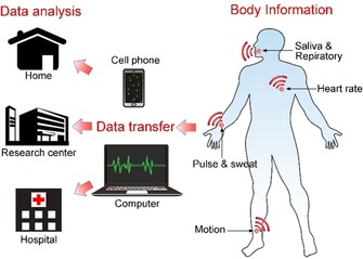
Acquisition of body information with wearable chemosensors. Health‐related body information is obtained by wireless wearable chemosensors and is converted into readable data by a mobile phone or a computer for further analysis.
Given that a lot of attention has been placed on the research of wearable chemosensors in recent years, these devices are more easily accessed in a variety of forms. Generally, wearable chemosensors can be sorted by the target stimuli to which they respond, including body fluids, body movements, physiological vital signs, and so on. In this Minireview, we summarize recent developments of wearable chemosensors and discuss their fabrication technology and medical applications.
2. Background
2.1. Composition of Typical Chemosensors
A typical chemosensor is composed of two basic functional units: a signal receptor and a physicochemical transductor.12, 27 Chemosensors are defined by the International Union of Pure and Applied Chemistry (IUPAC) as “a device that transforms chemical information, ranging from the concentration of a specific sample component to total composition analysis, into an analytically useful signal”. As shown in Figure 2, the receptor selectively catches the target analytes, and then the concentration of the analytes can be read out by various sensors. The raw data from the sensors are processed and are then showed on a display. Wearable chemosensors are designed on the basis of various types of chemosensor systems. Therefore, they can be classified on the basis of the fabrication principles of their receptors, catalytic or affinity principles, or type of sensors, such as electrochemical, piezoelectric, calorimetric, pressure sensitive, or optic sensors. Over decades, electro‐chemosensors have developed rapidly and have maintained a dominant position in clinical monitoring and diagnosis. Because of the high portability, compatibility, and flexibility of electro‐chemosensors, considerable efforts have been made to design wearable chemical sensors based on electrochemical sensors for the in situ monitoring of human health.12
Figure 2.

Schematic illustration of a chemosensor.
2.2. Key Enabling Technologies of Wearable Chemosensors
A wearable chemosensor for remote detection is usually composed of three basic parts: a sensing block used to obtain the physiological signals, a communication block to transmit the data information to a remote receptor (such as a smart phone or computer), and a signal converter to extract useful information from the signals collected by the sensing block.2
A major sensing technology for the successful establishment of wearable chemosensors is the miniaturization of electronic devices. Typically, the size of electronic devices can be significantly reduced by using batch fabrication techniques. With the rapid development of microelectronics, researchers are able to design miniature electronic circuits holding the three basic building blocks required by a typical wearable chemosensor.
As shown in Figure 3, flexible microcircuit‐based chips enable researchers to obtain original physiological signals and to transmit these signals to a remote receptor wirelessly by a low‐power radio. The signal amplifier, microcontroller (microprocessor), radio chip, and antenna are integrated simultaneously on a single chip, which is especially favorable for the system‐on‐chip implementation of wearable chemosensors.2, 28
Figure 3.
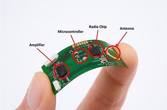
Illustration of a flexible wireless electronic sensor with a fully functional microcontroller developed by Interuniversity Microelectronics Centre (Courtesy of IMEC, the Netherlands). Reproduced from Ref. 2 with permission of the BioMed Central.
The stretchability of electrodes, defined as the ability of an electrode to maintain its conductivity under mechanical deformation, is another key factor for the successful building of wearable electronics.29, 30 Due to the high demand for human‐wearable device interfaces (usually curvilinear), large stretchability is needed to maintain the performance of the electrode.29 Stretchable electrodes can directly collect electronic signals for monitoring of physiological indicators.31, 32 For example, Chen et al.31 have developed a highly stretchable electrode with good conductivity on the basis of the highly stretchable sinusoidal structure of gold nanobelts, and they can be applied to record electrocorticograms. A unique out‐of‐plane tripod polydimethylsiloxane (PDMS) structure is used to support the conductive gold belts, which allows the suspended gold nanobelts to be used as stretchable electrodes (Figure 4).
Figure 4.
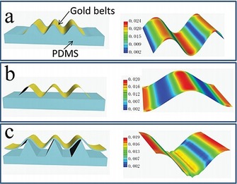
Schematic drawing of different prestretched structures and analysis of the relevant strain distribution by a full 3D finite element modeling (FEM) analysis method. a) Wrinkled structure, b) suspending structure, and c) tripod PDMS bending structure. Reproduced from Ref. 31 with permission of Wiley‐VCH.
However, as it is difficult to find fully conductive materials with high stretchability, composites of stretchable polymers with a conductive metal or carbon are used to obtain stretchability. Yet, the problem is the extremely different properties of the metal and the polymer, which causes poor adhesion between the electrodes and the substrates.29, 33 To solve this problem, one method is to form chemical bonds between the metal and the polymer substrate, typically disulfide bonds between the gold film and the polymer. The disadvantage of this method is that disulfide bonds are not stable under physiological conditions. In this case, a physical interlocking layer between the metal and the polymer is necessary to achieve high adhesion. Thus, the physical method may generate more stretchable electrodes for the design of wearable devices.
3. Fabrication Methods
Wearable chemosensor technologies are essential to realize real‐time monitoring of an individual's health states and activities; thus, much effort has been expended into developing fabrication methods for various wearable chemosensors. The most widely used sensor systems are based on electrochemical sensors. Here, we want to introduce several typical fabrication technologies.
3.1. Screen Printing
The limitations of large solid‐state electrodes include unsatisfactory sensitivity and quick patient fatigue.34 To solve the disadvantages encountered with solid‐state electronic devices, screen‐printed electrodes have been developed due to their convenient fabrication at an industrial scale, low cost, favorable electroanalytical performance, and good compatibility with wearable devices.35, 36 Screen‐printed electrodes have been adaptively applied in glucose detection, medical diagnosis, and so on.
Windmiller and Wang37 describe basic methods for the fabrication of textile‐based screen‐printed electrodes and the fundamental requirements. The fabrication of flexible screen‐printed electrodes includes three basic steps: first, a design is proposed and optimized according to the demands of the application; second, the design is then fabricated on laser‐cut stainless steel or chemically etched polymeric‐mesh‐screen stencils; third, the printing parameters are finally optimized.
As shown in Figure 5, after optimizing the printing parameters, the textile substrate is placed on the substrate platform. An ink based on Ag/AgCl is applied for the formation of the conductive underlayer, which also works as the reference electrode patterned directly on the substrate textile. Afterwards, a metal/carbon‐based ink is covered on the Ag/AgCl layer. Each printing step is performed in a temperature‐controlled convection oven at the optimized temperature to evaporate the solvent to ensure the purity of the solids contents. Scanning electron microscopy is usually employed to characterize the surface morphology of the printed electrodes.
Figure 5.
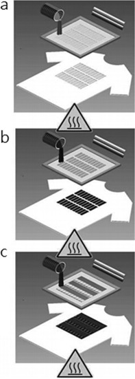
Steps involved in screen printing electrochemical sensors and biosensors on textile substrates. Reproduced from Ref. 37 with permission of Wiley‐VCH.
Electrode arrays composed of a large number of small screen‐printed electrodes are gaining popularity due to their potential to deliver selective electrical stimulation to underlying muscles.38 Yang et al.39 present a flexible and breathable fabric electrode array based entirely on screening‐printing electrodes directly printed on a standard fabric.
As shown in Figure 6, the printed fabric electrode array is fabricated on bespoke polymer‐based screen‐printable pastes that are compatible with textiles. All the materials with skin contact are biocompatible. Relative to the performance of a flexible printed circuit board (PCB) array on polycarbonate with a hydrogel layer (Fatronik‐Tecnalia, Spain, Figure 6 b), the performance of the fabric electrode array is significantly improved, especially as regards the flexibility, breathability, and comfort. This fabric electrode array shows great potential for printable polymer materials to realize comfortable, wearable, and cost‐effective functional systems in healthcare applications.
Figure 6.
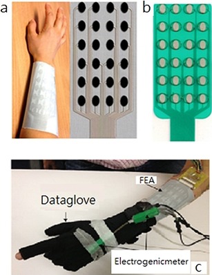
a) Fabric electrode array. b) Flexible printed circuit board (PCB) array from Fatronik–Tecnalia. c) Monitoring system for a fabric electrode array (FEA) based on hand movements. Reproduced from Ref. 39 with permission of Elsevier.
Freeman40 developed the first model‐based electrode arrays to give functional electrical stimulation to underling muscles. As shown in Figure 7 a, the hardware consists of an element electrode array, and each array element can be routed to one functional electrical stimulation channel. Routing is achieved by using custom‐made hardware that can generate a 5 V, 40 Hz square pulse train with variable pulsewidths. The electrode array is positioned as shown in Figure 7 b to cover the wrist and finger extensor muscles, including the extensor carpi radialis longus, extensor carpi radialis brevis, extensor digitorum, extensor pollicis longus, extensor pollicis brevis, extensor indius, and flexor digitorum profundus.
Figure 7.
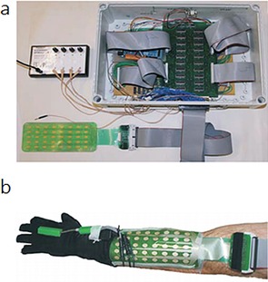
a) Electrode array, multiplexor hardware, and stimulator. b) Electrode array, data glove, and electrogoniometer. Reproduced from Ref. 40 with permission of Elsevier.
3.2. Droplet‐Based Printing
Droplet‐based printing, typically inkjet and aerosol jet printing, have developed rapidly in recent years. As a promising fabrication technique for the design of electrochemical devices, the droplet‐based printing method may enable precise thin‐layer deposition and system integration of a microcircuit.41
Inkjet printing is based on a two‐dimensional printer that uses a jet to deposit tiny drops of ink onto a substrate. Originally appearing in the 1970s, the ink consists of a dye of pigments and has mainly been used to produce digital images generated by computers.42 Since the beginning of the 21st century, inkjet printing has further been used in the printing of inks consisting of functional materials, including metallic nanoparticles, polymers, carbon nanotubes, and so on with applications in the fields of organic electronics, cell culturing, and tissue engineering.43 As shown in Figure 8, the inks are deposited drop by drop to form functional layers, and then a three‐dimensional device is obtained layer by layer.
Figure 8.
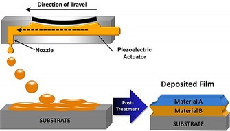
Schematic depiction of the creation of a multilayer material through drop‐on‐demand printing. Individual ink drops coalesce to form wet layers. Solvent from the wet layer evaporates to form dry layers. These dry layers may serve as substrates for deposition of the next material. After all layers are deposited, postprinting treatment may be used to remove residual solvent or additives or to cross‐link polymers. Reproduced from Ref. 41 with permission of Wiley‐VCH.
Similar to inkjet printing, aerosol jet printing is a material‐deposition technique for the precise, controlled deposition of drops in well‐defined locations.42 The main process of the droplet‐based printing of functional materials includes four parts: ink formulation, drop deposition, wet film layer formation, and consolidation.41 Inkjet and aerosol jet printing have different working mechanisms for printing. For inkjet printing, the ink is stored in a cartridge and is pushed out from the nozzles drop by drop, and then the drops are co‐deposited to form functional layers. In aerosol jet printing, the ink is stored in a reservoir and is then atomized into a mist (Figure 9). For both inkjet and aerosol jet printing, thousands of drops are sent to the substrate surface per second, whereas the drying process takes seconds to minutes.44 In this case, the final drop overlap is dependent on drop impact, capillary forces, the surface morphology of the substrate, the temperature of the substrate, and the interaction between the ink and the substrate.45 The final step of the printing process is consolidation of the wet printed layer by removing the additives in the ink, such as solvents, surfactants, and dispersant. For both inkjet and aerosol jet printing, the consolidation step works separately and is mainly dependent on the plate temperature, the thickness of the printed layers, the composition of the functional layers, and the substrate structure.
Figure 9.
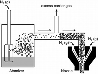
Schematic of the aerosol jet deposition process. In the atomizer, the carrier gas (here depicted as N2) flows rapidly above a nozzle immersed in the ink reservoir. The rapidly flowing gas creates a region of low pressure that results in the formation of aerosol droplets. Small droplets are entrained in the carrier gas, whereas larger droplets return to the ink reservoir. As the stream of entrained droplets progresses toward the nozzle, it is concentrated through the removal of excess carrier gas. In the nozzle, a flowing sheath gas (here depicted as N2) focuses the concentrated aerosol. Reproduced from Ref. 41 with permission of Wiley‐VCH.
3.3. Lithography Printing
As a printing technology, lithography was initially invented in 1796 as a cheap method to print text onto paper or another material on the basis of the immiscibility of oil and water. In modern times, lithography has been used in the fabrication of integrated circuits and micro/nanoelectronic devices.46 Photolithography, also called optical lithography or UV lithography, uses light to transfer a geometric pattern onto a photomask to a light‐sensitive substrate, typically a thin film.47 Then, the desired pattern is transferred to the substrate layer. Currently, photolithography is the standard patterning technique in the industry and is the most reliable technique.46, 47 However, the achievable resolution is limited and is unsuitable for nanoscale fabrication.48, 49 For nanoscale lithography, the most common method is electron beam lithography (EBL).50, 51 Yet, the operation of EBL needs ultrahigh vacuum and high energy, and the throughput of EBL is far behind industry standards. Therefore, significant effort has been put into inventing alternative lithography techniques. A new lithography technique, electrolithography, has been proposed, and it is based on the electromigration of a liquid in thin metal films.48 Electromigration is a material‐transport process that is controlled by an electric current, and it can be used to generate hillocks and voids in metals.52
Pratap et al.48 report an electrolithography technique by passing electric current through an infinite Cr thin film deposited on a SiO2‐Si substrate (Figure 10). By applying a high electric current, the molten Cr compound flows quickly outward from the cathode to form a ring‐shaped pattern around the tip.
Figure 10.
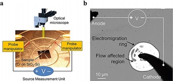
Electromigration‐induced radially symmetric flow. a) Schematic illustration of the experimental setup for passing an electric current through a thin Cr film deposited on a substrate. b) An optical image showing formation of a typical electromigration ring around the cathode probe (solid black parts are needle probes). The ring is created on a 20 nm Cr film deposited on a SiO2‐Si substrate. Reproduced from Ref. 48 with permission of Nature Publication Group.
As shown in Figure 11, as the cathode tip moves along a path, the radial symmetry of the flow breaks, and liquid Cr flows away from the path and forms a trench pattern through the etching process. Afterwards, the polymer layer of the etched region between the metal and the substrate is removed, and then new material is deposited onto the exposed substrate. After the pattern is printed to the top material, the remaining polymer together with the Cr film are removed.
Figure 11.
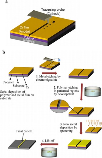
Important steps in the standard electrolithography process. a) Electromigration‐driven metal etching by a traversing probe. As the negatively biased tip moves, the Cr compound formed below the cathode melts and flows away from the path, which creates a groove along the path traversed. The dashed arrow shows the direction in which the tip is traversed. b) Process flow of the standard electrolithography technique. The process starts with a substrate spin coated with a polymer followed by deposition of a Cr thin‐film top layer. 1) In the first step, the top Cr layer is etched in the desired pattern by using electromigration. 2) Next, the polymer is etched in the patterned region by dipping it in an appropriate solvent. The inset shows the zoomed view of the trench made in the polymer. 3) Subsequently, the desired material is deposited. 4) Lift off is used to transfer the final pattern onto the desired material. Reproduced from Ref. 48 with permission of Nature Publication Group.
3.4. Pick‐and‐Place‐Based Methods
A pick‐and‐place machine is a robotic assembly device that can lift a component to a correct orientation and then place it on a circuit board or substrate. It is a convenient technique to generate an electronic assembly. For nanoscale deposition, the most widely used technique is scanning probe lithography, as it can deposit nanoparticles or molecules selectively onto a substrate by pick‐and‐place operations.53 Typically, an atomic force microscope (AFM) probe is utilized to transfer a substance to the substrate surface for patterning nanoscale features.54 Traditionally, probe tips are made of hard materials such as silicon and silicon nitride. The sharp probe is wrapped with a thin film of a certain chemical substance by immersing the cantilever in the solution, and then functional molecules are deposited onto the surface of the substrate during contact between the tip and the substrate (Figure 12).53, 54
Figure 12.
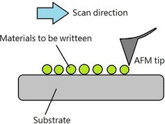
Schematic illustration of scanning‐probe‐based lithography.
Nanomanipulation based on pick and place is slow relative to the time needed to grow structures directly on the target device. However, pick‐and‐place nanomanipulation shows great potential and favorable flexibility and allows customized assembly of a wide range of nanomaterials with different morphologies and sizes in different cases.
4. Substrates for Wearable Chemosensors
4.1. Electronic Textiles
Electronic textiles refer to a broad field of textile products, such as filaments and fibers, that are capable of featuring electronics.55 Electronic textiles have physical flexibility and a typical size that cannot be achieved by traditional electronic techniques.55 The special properties of electronic textiles make them conveniently adaptable to sensing requirements for wearable chemosensors. Over the past decade, scientists have developed different techniques and materials for the design and fabrication of smart textiles with various properties and functions. These electronic textiles are based on a variety of different technologies such as embroidery, sewing, weaving, and so on (Figure 13).
Figure 13.
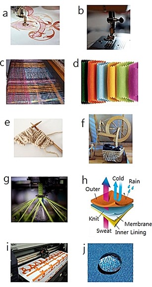
Different kinds of textile/fabric manufacturing. a) Embroidery, b) sewing, c) weaving, d) nonwoven, e) knitting, f) spinning, g) braiding, h) coating/laminating, i) printing, and j) chemical treatment. Reproduced from Ref. 55 with permission of MDPI.
Wang et al.56 have developed a wearable, flexible, and stretchable glove‐based electrochemical biosensor for the detection of organophosphorus chemicals. As shown in Figure 14, they present the first design for performing fingertip enzymatic assays. The glove‐based sensor uses different fingers to perform the sampling and biosensing steps; the enzyme is fixed on the index finger, and the thumb is used to collect residue. This flexible, wearable “lab‐on‐a‐glove” combines an enzyme‐immobilized biosensing detection finger, a sampling finger, and wireless real‐time data transmission to a smart phone.
Figure 14.
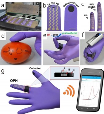
Flexible glove biosensor: fabrication, design, and performance. a) Image of the serpentine stencil design employed for printing the glove‐based stretchable device. b) Schematic of (left) the biosensing scan finger (index finger) containing a smiling face shape carbon‐based counter (CE), working electrode (WE), and Ag/AgCl‐based reference electrode (RE), and (right) collecting thumb with its printed carbon pad; scale bar: 10 mm. c) Photographs of the biosensing index finger under 0 % (left) and 50 % (right) linear stretch; scale bar: 10 mm. d) On‐glove swiping protocol for sampling chemical threat residues from tomato and stainless‐steel surfaces. e) On‐glove sensing procedure by joining the index finger (scan) and thumb (collector) to complete the electrochemical cell. f, g) Photographs of the wearable glove biosensor consisting of a sensing finger containing the immobilized organophosphorus hydrolase (OPH) enzyme layer and the collector/sampling finger. The electrodes are connected by an adjustable ring bandage to the portable potentiostat (attached to the back of the hand) for on‐site detection with wireless communication to a smart phone for rapid presentation of the voltammetric results. The inset shows a schematic of the interface between potentiostat and glove sensor. The connections consist of a Velcro fabric (iii) containing the aluminum‐tape based pins (ii) that are adjusted as a ring with the glove sensing connectors and the wiring (i) with the potentiostat. Reproduced from Ref. 56 with permission of the American Chemical Society.
4.2. Tattoo‐Based Wearable Electrochemical Devices
The skin provides us with the sense of touch and protects our internal body systems from the surrounding environment as a strong barrier.57 The design of skin‐wearable devices must be flexible to fit the special morphology of human skin. Although many textile‐based electronic sensors have been developed as skin sensors, they are limited in use, as they cannot contact every region on the body continuously.57, 58, 59 In this case, epidermal tattoos (E‐tattoos) have developed quickly in recent years; they are ultrasoft and thin, and this enables them to match human skin intimately with long‐term, highly sensitive, and stable biosensing abilities. E‐tattoos provide a new approach for “printing” electrochemical devices directly onto human skin without influence to the wearer's daily routine.57
Wang's group60 has developed the first temporary tattoo‐based electrochemical sensors for both physiological analysis and environmental monitoring. As shown in Figure 15, they print active ink materials such as carbon and Ag/AgCl on tattoo papers to obtain sensor electrodes with various functions. This synthetic epidermal sensor design can be conveniently applied to a wearer's skin just like a tattoo (Figure 16).
Figure 15.
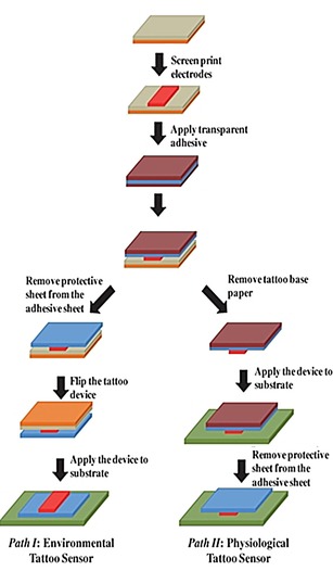
Fabrication of printable tattoo‐based electrochemical devices. Reproduced from Ref. 60 with permission of Wiley.
Figure 16.
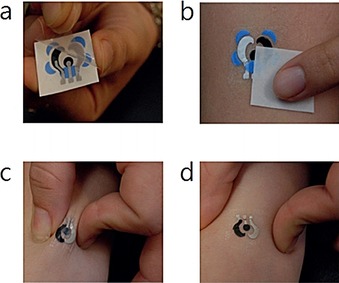
Photographs showing standard steps of a) removing the transparent protective sheet and b) gently sliding the tattoo‐based paper after dabbing it with water to apply a tattoo device to human skin. Images showing extent of mechanical stress experienced by a tattoo applied to a human subject during c) stretching and d) twisting of the underlying skin. Reproduced from Ref. 60 with permission of Royal Society of Chemistry.
Lu et al.61 report a stretchable and transparent graphene E‐tattoo (GET) sensor that is sub‐micrometers in thickness. The GET is fabricated by a simple “wet transfer, dry patterning” process directly onto tattoo paper, which enables the GET to contact human skin like a temporary tattoo. As shown in Figure 17, “wet transfer” refers to the copper‐etching step, which ensures high continuity of the large‐area graphene grown on copper foil, and “dry patterning” refers to the application of a programmable mechanical cutter plotter to carve out the designed shapes on the graphene sheet.61 This design requires no skin preparation or skin adhesive, and the ultrathin GET can attach to human skin closely through van der Waals interactions. The GET has successfully been applied to the detection of electrocardiogram (ECG), electromyogram (EMG), electroencephalogram (EEG), skin temperature, and skin hydration.
Figure 17.
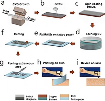
Fabrication process of a GET. a, b) Graphene is grown on copper foil by using atmospheric pressure chemical vapor deposition (CVD). c) A layer of poly(methyl methacrylate) (PMMA) less than 500 nm thick is spin coated on graphene. d) Copper is etched away. e) Graphene/PMMA (Gr/PMMA) is transferred onto tattoo paper with PMMA touching the paper and graphene facing up. f) Gr/PMMA is cut by a mechanical cutter plotter. g) Extraneous Gr/PMMA is peeled off from the tattoo paper. h) Mounting GET on skin like a temporary transfer tattoo. i) GET on skin. Reproduced from Ref. 61 with permission of the American Chemical Society.
5. Applications
Wearable chemosensors have many advantages over conventional rigid electrodes due to their flexible and even stretchable properties, and this gives them strong potential to be used in body sensing. Here, we would like to introduce the recent medical applications of wearable chemosensors. This part provides a review of the recent advantages of wearable chemosensor systems and is organized into three subsections to introduce applications focused on sweat‐based analysis, saliva‐based analysis, and tear‐based analysis.
5.1. Sweat‐Based Analysis
Human sweat, an easily accessible body fluid, contains a variety of chemical biomarkers reflecting the state of human health.62, 63, 64 Changes in the chemical composition of sweat can show a variety of clinical conditions in the human body. Measurements of human sweat are noninvasive, easy, and can be done without risk of infection. Recently, several noninvasive methods have been designed to detect the chemical markers in sweat.
Electronic chemosensors are especially attractive for the design of diagnostic devices, owing to their ease of fabrication, integration, low cost, and good portability.65 Potentiometric sensors with simple fabrication techniques such as screen printing provide a relatively simple and convenient method for on‐body sweat measurement. Searson et al.66 show a typical noninvasive potentiometric sweat sensor as a means to measure chloride in on‐body sweat. Potentiometric detection is a well‐established analytical method and relies mainly on correlations between ion concentration and electrochemical potential of the electrode. This wearable potentiometric sensor comprises a reference chamber with a solution of known concentration and a test solution (Figure 18 a). The incorporation of a salt bridge is the key to control the equilibration rate between the reference and test solutions (Figure 18 b), which can cause a decrease in cell voltage.
Figure 18.
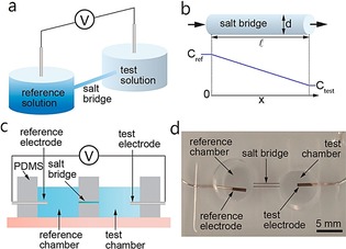
Potentiometric sensor. a) A potentiometric sensor measures the potential between the reference and test solutions. b) The geometry of the salt bridge controls equilibration between the reference and test solutions. c) Schematic illustration of a sensor for parametric studies. d) Sensor for parametric studies. Reproduced from Ref. 66 with permission of the American Chemical Society.
Changes in the concentrations of the chloride ions in the reference and test solutions per unit time can be measured by the flux of ions (J) and the salt bridge geometry [Eqs. (1), (2)]:
| (1) |
| (2) |
in which C test(t) and C ref(t) are the concentrations of the reference and test solutions, respectively; J [mol m−2 s−1] is the flux of ions; A eff is the effective cross‐sectional area of the salt bridge; t is time; d is the diameter of the salt bridge; p is the porosity of the hydrogel; and v test and v ref are the volumes of the test and reference solutions, respectively.
The concentration drift rate, Q [M h−1], through the salt bridge can be calculated by the following equation [Eq. (3)]:
| (3) |
in which i represents the test and reference solutions. The ion flux is dominated by diffusion; thus, Equation (3) can be simplified to [Eq. (4)]:
| (4) |
in which D is the diffusion coefficient of chloride ions and C(x,t) is the concentration distribution of chloride ions within the salt bridge.
Given that the concentration gradient in the salt bridge is linear at steady state, the concentration drift rate can be described as [Eq. (5)]:
| (5) |
in which l is the length of the salt bridge. From Equation (5), Q is proportional to the square of the diameter of the salt bridge and the concentration difference between the reference and the test solution and is inversely proportional to the length of the salt bridge. Given that the concentration of the reference solution (1 m) is much larger than that of the test solution (10 mm), sensor voltage changes are dominated by the concentration of the test solution. The sensor voltage at room temperature is given as [Eq. (6)]:
| (6) |
The change in sensor voltage is given by [Eq. (7)]:
| (7) |
From Equation (7), the change in chloride ion concentration in the test solution can be measured from the change in sensor voltage.
Figure 19 a, b shows the fabricated on‐body sensor, which is composed of Ag/AgCl reference and test electrodes, a reference chamber, and a salt bridge filled with hydrogel (1 m KCl). Calibration curves are highly reproducible upon using 10, 50, and 100 mm NaCl solutions, with a slope of 50 mV dec−1 (Figure 19 c). Dose–response curves show fast response (Figure 19 d).
Figure 19.
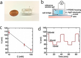
Chloride sensor for on‐body sweat tests. a) Photograph of a sensor. b) Schematic illustration of the sensor with an optimized salt bridge. c) Representative calibration curve (N=13). d) Representative dose–response curve. Reproduced from Ref. 66 with permission of the American Chemical Society.
Gao et al.67 have develop a flexible and fully integrated sensor array for multiplexed sweat analysis in situ, and it can simultaneously measure several sweat chemicals (e.g., glucose and lactate), electrolytes (including sodium and potassium ions), and skin temperature. This wearable system can be used to measure the detailed sweat profile in real time. As shown in Figure 20, they present a wearable flexible integrated sensing array (FISA) for the simultaneous and selective detection of several chemical biomarkers in sweat, including temperature and glucose, lactate, Na+, and K+ levels. Signal transduction, conditioning, and processing in addition to wireless transmission are integrated on a flexible printed circuit board (FPCB) with a flexible and conforming sensor integrated on a plastic substrate.
Figure 20.
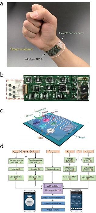
Images and schematic illustration of the FISA for multiplexed perspiration analysis. a) Photograph of a wearable FISA on a subject's wrist, integrating the multiplexed sweat sensor array and the wireless FPCB. b) Photograph of a flattened FISA. The red dashed box indicates the location of the sensor array, and the white dashed boxes indicate the locations of the integrated circuit components. c) Schematic of the sensor array for multiplexed perspiration analysis. GOx: glucose oxidase, LOx: lactate oxidase. d) System‐level block diagram of the FISA showing the signal transduction (orange) [with potential (V), current (I), and resistance (R) outputs], conditioning (green), processing (purple), and wireless transmission (blue) paths from sensors to the custom‐developed mobile application (numbers in parentheses indicate the corresponding labeled components in panel b). ADC, analogue‐to‐digital converter. The inset images show the home page (left) and real‐time data display page (right) of the mobile application. Reproduced from Ref. 67 with permission of Nature Publication Group.
As shown in Figure 20 a, the FISA can simultaneously detect a panel of metabolites and electrolytes in human perspiration in addition to skin temperature. A stable sensor–skin contact can be obtained by fabricating the sensor on a flexible polyethylene terephthalate (PET) substrate (Figure 20 b). Figure 20 c shows the schematic design of the multiplexed sensor array (each electrode is 3 mm in diameter) for sweat analysis. For the detection of glucose and lactate, amperometric glucose and lactate sensors are based on glucose oxidase and lactate oxidase, respectively, which are immobilized within a permeable film of polysaccharide chitosan. A Ag/AgCl electrode is used as a shared reference electrode and counter electrode. For the measurement of Na+ and K+, ion‐selective electrodes (ISEs) are used coupled with a polyvinyl butyral (PVB)‐coated reference electrode. A resistance‐based temperature sensor is established by fabricating Cr/Au metal microwires by using parylene as an insulating layer to prevent electrical contact between the metal lines and skin. Figure 20 d shows the signal conditioning path for each sensor with analogue circuits, which are integrated to ensure the final output. The transceiver enables convenient wireless data transmission to a Bluetooth smart phone. With a custom‐developed application (mobile APP), the multiplexed sensor array can show real‐time measurement results on a mobile phone. This platform can also be applied for the in situ analysis of other biomarkers in sweat and other human fluid samples.
5.2. Saliva‐Based Analysis
Saliva is a watery substance secreted by the salivary glands in the mouths of animals. Human saliva contains 99.5 % water, electrolytes, mucus, white blood cells, epithelial cells, glycoproteins, enzymes, and tec.12 Therefore, saliva is an effective sample that can be used to monitor human health.68 Recently, rapid developments have been achieved in the field of wearable salivary analysis.
Up to now, electrochemical sensors have been much more attractive than optical approaches due to their easy fabrication and integration. The fabrication of wearable salivary sensing has witnessed considerable progress, aimed primarily towards the incorporation of electrochemical minidevices with partial dentures. McAlpine et al.69 have developed a novel dental tattoo for the continuous wireless monitoring of bacteria in saliva by using graphene‐modified silk tattoo substrates functionalized with antimicrobial peptides. As shown in Figure 21, large‐area graphene monolayers are integrated with silk fibroin films through transfer printing. The thin film fabricated on silk can be integrated on a human molar for the real‐time noninvasive detection of bacteria through antimicrobial peptides functionalized on the silk tattoo substrate.
Figure 21.
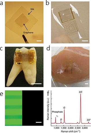
Illustration of the wireless tattoo‐based resistive sensor for Staphylococcus aureus. Reproduced from Ref. 69 with permission of Nature Publication Group.
Wang's group70, 71 has designed a series of wearable mouth‐guard biosensors capable of noninvasively detecting lactate70 and uric acid56 levels in human saliva with good sensitivity and selectivity.
5.3. Tear‐Based Analysis
In humans, tears are made up of a variety of chemical components, including proteins, electrolytes, and lipids. Therefore, tears can be used for the noninvasive monitoring of human health. Traditional in vitro tear detection requires the use of extracted human tear samples.72, 73 However, there are several disadvantages of in vitro sensors. For example, the concentration of the analytes in tears can be severely affected by fast evaporation of the tear samples during the detection process. Therefore, wearable tear sensors, which can work directly on the retina, may solve the problem. Early forms of wearable tear sensors were based on bare electrodes fabricated on flexible substrates by using standard lithographic techniques.74
As shown in Figure 22, Iguchi et al.74 have developed a flexible and wearable sensor for the analysis of glucose levels in tear fluids on the eye of a rabbit. The sensor is made by immobilizing glucose oxidase (GOD) onto a flexible oxygen electrode, which is fabricated onto a polymer film, with a detection linear range of 0.025 to 1.475 mm.
Figure 22.
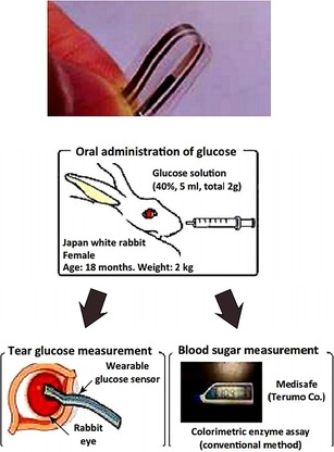
A flexible strip‐based glucose sensor and the method for applying the sensor for tear glucose measurements in the eye of a rabbit. Reproduced from Ref. 74 with permission of Springer.
However, most strip‐based sensors are fabricated on partially flexible substrates, which may cause eye irritation.74, 75, 76 In this case, soft‐contact‐lens‐based wireless sensors have been developed to solve the above limitations. Parviz's group has designed contact lens glucose sensors based on wireless electronics, which are now developed by Google.77, 78 As shown in Figure 23, Google has developed smart contact lenses made of a common lens hydrogel material that is embedded with a tiny wireless chip, a miniaturized glucose sensor, and a tiny battery; this device realizes noninvasive glucose analysis through measurement of tears.78
Figure 23.
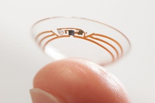
Google smart lens for noninvasive blood‐glucose monitoring by detection of tear fluid. Reproduced from Ref. 78 with permission of Nature Publication Group.
6. Conclusions and Future Prospects
In this Minireview, we summarized some recent developments and progress in the design of wearable chemosensors. The wide application of wearable chemosensors in the healthcare system makes them convenient tools for the detection and long‐term monitoring of the chemical, biological, and physical status of the human body in real time. An increasing amount of attention is being focused on concrete clinical applications of wearable chemosensors with high sensitivity and stability. With the participation of big business groups, such as Google, the commercialization of wearable, noninvasive electro‐chemosensors is expected to be realized in the near future.
Wearable chemosensors belong to a cross‐disciplinary research field comprising chemistry, biology, materials science, and electronics. At present, a great deal of work directed towards the development of wearable chemosensors has been published, and some devices have been applied in clinical healthcare. Nevertheless, there are still several challenges that need to be addressed to improve the performance of wearable chemosensors, such as long‐term stability, stretchability of the electrodes, biocompatibility, comfort level, system integration, costs, and so on. For example, stretchability is an important factor that may influence the performance of epidermal sensors, especially during intense physical body movements. Much effort is still needed to improve the performance of the materials in wearable sensors. In addition, much attention has been paid to bioanalytes such as pathogens, amino acids, and enzymes, and we believe the potential application fields of wearable chemosensors can be further expanded to the exploration of the pathogenesis of various diseases, such as cancer. At the same time, the integration of multiple technologies will be significantly improved with the development of novel techniques. Therefore, more work is needed to improve the quality of wearable chemosensors for better practical use.
Conflict of interest
The authors declare no conflict of interest.
Biographical Information
Ruo‐Can Qian graduated with a BS degree from Nanjing University (PR China) in 2009. She received her PhD in Analytical Chemistry from the same university in 2014. After completing her two‐year postdoctoral research work at East China University of Science and Technology (Shanghai, PR China), she was appointed as an Associate Research Fellow at the same university. Her current research interests mainly focus on cell pathway analysis, single cell imaging, biosensors, and nanoelectrochemical analysis.

Biographical Information
Yi‐Tao Long received his PhD in Bioelectroanalytical Chemistry from Nanjing University (PR China) in 1998. After completing his two‐year postdoctoral studies at Heidelberg University (Germany), he moved to Canada and worked for five years as a Research Scientist at the University of Saskatchewan and University of Alberta. Dr. Long was appointed as Full Professor at East China University of Science and Technology (Shanghai, PR China) in 2007 after he worked in the Department of Bioengineering at UC Berkeley (USA). His main research expertise involves nanopore single‐molecule analysis, nanospectroscopy, spectroelectrochemistry, integrated biosensors, and biointerphases.

Acknowledgements
This research was supported by the National Natural Science Foundation of China (21421004, 21327807, 21605048), the Program of Introducing Talents of Discipline to Universities (B16017), Innovation Program of Shanghai Municipal Education Commission (2017‐01‐07‐00‐02‐E00023), the Fundamental Research Funds for the Central Universities (222201718001, 222201717003), Chenguang Program (16CG35), and Shanghai Education Development Foundation and Shanghai Municipal Education Commission.
R.-C. Qian, Y.-T. Long, ChemistryOpen 2018, 7, 118.
References
- 1. Pantelopoulos A., Bourbakis N. G., IEEE Trans. Sys. Man Cybernet. 2010, 40, 1–12. [Google Scholar]
- 2. Patel S., Park H., Bonato P., Chan L., Rodgers M., J. NeuroEng. Rehabil. 2012, 9, 21. [DOI] [PMC free article] [PubMed] [Google Scholar]
- 3. Gatzoulis L., Iakovidis I., IEEE Eng. Med. Biol. Mag. 2007, 26, 51–56. [DOI] [PubMed] [Google Scholar]
- 4. Bonato P., J. NeuroEng. Rehabil. 2005, 2, 2. [DOI] [PMC free article] [PubMed] [Google Scholar]
- 5. Bonato P., IEEE Eng. Med. Biol. Mag. 2003, 22, 18–20. [DOI] [PubMed] [Google Scholar]
- 6. Mukhopadhyay S. C., IEEE Sens. J. 2015, 15, 1321–1320. [Google Scholar]
- 7. Hao Y., Foster R., Phys. Meas. 2008, 29, 27–56. [DOI] [PubMed] [Google Scholar]
- 8. Rienzo M. D., Rizzo F., Parati G., Brambilla G., Ferratini M., Castiglioni P., IEEE Eng. Med. Bio. 2005, 27, 7167–7169. [DOI] [PubMed] [Google Scholar]
- 9. Salvo P., Di Francesco F., Costanzo D., Ferrari C., Trivella M. G., De Rossi D., IEEE Sens. J. 2010, 10, 1557–1558. [Google Scholar]
- 10. Mariani B., Jiménez M. C., Vingerhoets F. J. G., Aminian K., IEEE Trans. Biomed. Eng. 2013, 60, 155–158. [DOI] [PubMed] [Google Scholar]
- 11. Xu S., Zhang Y., Jia L., Mathewson K. E., Jang K. I., Kim J., Fu H., Huang X., Chava P., Wang R., Bhole S., Wang L., Na Y. J., Guan Y., Flavin M., Han Z., Huang Y., Rogers J. A., Science 2014, 344, 70–74. [DOI] [PubMed] [Google Scholar]
- 12. Bandodkar A. J., Wang J., Trends Biotechnol. 2014, 32, 363–371. [DOI] [PubMed] [Google Scholar]
- 13. Bandodkar A. J., Jeerapan I., Wang J., ACS Sens. 2016, 1, 464–482. [Google Scholar]
- 14. Jin H., Abu-Raya Y. S., Haick H., Adv. Healthcare Mater. 2017, 6, 1700024. [DOI] [PubMed] [Google Scholar]
- 15. Rodgers M. M., Pai V. M., Conroy R. S., IEEE Sens. J. 2015, 15, 3119–3126. [Google Scholar]
- 16. Pang C., Lee C., Suh K. Y., J. Appl. Polym. Sci. 2013, 130, 1429–1441. [Google Scholar]
- 17. Leonov V., IEEE Sens. J. 2013, 13, 2284–2291. [Google Scholar]
- 18. Inomata A., Yaginuma Y., FUJITSU Sci. Technol. 2014, 50, 78–83. [Google Scholar]
- 19. Chen B.-R., IEEE Trans. Biomed. Eng. 2011, 58, 831–836. [DOI] [PubMed] [Google Scholar]
- 20. Patel S., IEEE Trans. Inf. Technol. Biomed. 2009, 13, 864–873. [DOI] [PMC free article] [PubMed] [Google Scholar]
- 21. Shany T., Redmond S. J., Narayanan M. R., Lovell N. H., IEEE Sens. J. 2012, 12, 658–670. [Google Scholar]
- 22. Raveendranathan N., IEEE Sens. J. 2012, 12, 583–593. [Google Scholar]
- 23. Fontana J. M., Farooq M., Sazonov E., IEEE Trans. Biomed. Eng. 2014, 61, 1772–1779. [DOI] [PMC free article] [PubMed] [Google Scholar]
- 24. Teng X.-F., Zhang Y.-T., Poon C. C. Y., Bonato P., IEEE Rev. Biomed. Eng. 2008, 1, 62–74. [DOI] [PubMed] [Google Scholar]
- 25. Dobkin B. H., Dorsch A., Neurorehabil. Neural Repair 2011, 25, 788–798. [DOI] [PMC free article] [PubMed] [Google Scholar]
- 26. Appelboom G., Camacho E., Abraham M. E., Bruce S. S., Dumont E. L. P., Zacharia B. E., D'Amico R., Slomian J., Reginster J. Y., Bruyère O., E. S. Connolly Jr. , Arch. Public Health 2014, 72, 28. [DOI] [PMC free article] [PubMed] [Google Scholar]
- 27. Turner A., Trends Biotechnol. 2013, 31, 119–120. [DOI] [PubMed] [Google Scholar]
- 28. Brand O., P. IEEE 2006, 94, 1160–1176. [Google Scholar]
- 29. Chen X., Small Methods 2017, 1, 1600029. [Google Scholar]
- 30. Liu Y., He K., Chen G., Leow W. R., Chen X., Chem. Rev. 2017, 17, 12893–12941. [DOI] [PubMed] [Google Scholar]
- 31. Qi D., Liu Z., Yu M., Liu Y., Tang Y., Lv J., Li Y., Wei J., Liedberg B., Yu Z., Chen X., Adv. Mater. 2015, 27, 3145–3151. [DOI] [PubMed] [Google Scholar]
- 32. Guo C. F., Sun T., Liu Q., Suo Z., Ren Z., Nat. Commun. 2014, 5, 3132. [DOI] [PubMed] [Google Scholar]
- 33. Huang Y., Huang Y., Meng W., Zhu M., Xue H., Lee C.-S., Zhi C., ACS Appl. Mater. Interfaces 2015, 7, 2569–2574. [DOI] [PubMed] [Google Scholar]
- 34. Malešević N., Maneski L. Z., Ilic V., Jorgovanovic N., Bijelic G., Keller T., Popovic D., Neuroeng. Rehabil. 2012, 9, 66. [DOI] [PMC free article] [PubMed] [Google Scholar]
- 35. Metters J. P., Kadara R. O., Banks C. E., Analyst 2011, 136, 1067–1076. [DOI] [PubMed] [Google Scholar]
- 36. Alonso-Lomillo M. A., Renedo O. D., Martinez M. J. A., Talanta 2010, 82, 1629–1636. [DOI] [PubMed] [Google Scholar]
- 37. Windmiller J. R., Wang J., Electroanalysis 2013, 25, 29–46. [Google Scholar]
- 38. Heller B. W., Clarke A. J., Good T. R., Healey T. J., Nair S., Pratt E. J., Reeves M. L., van der Meulen J. M., Barker A. T., Med. Eng. Phys. 2013, 35, 74–81. [DOI] [PubMed] [Google Scholar]
- 39. Yang K., Freeman C., Torah R., Beeby S., Tudor J., Sens. Actuators A 2014, 213, 108–115. [Google Scholar]
- 40. Freeman C. T., Control Eng. Prac. 2014, 23, 32–43. [Google Scholar]
- 41. Deiner L. J., Reitz T. L., Adv. Eng. Mater. 2017, 19, 1600878. [Google Scholar]
- 42. Fundamentals of Inkjet Printing: The Science of Inkjet and Droplets (Ed.: S. D. Hoath), Wiley-VCH, Weinheim, 2016. [Google Scholar]
- 43. Singh M., Haverinen H. M., Dhagat P., Jabbour G. E., Adv. Mater. 2010, 22, 673–685. [DOI] [PubMed] [Google Scholar]
- 44. Derby B., J. Eur. Ceram. Soc. 2011, 31, 2543–2550. [Google Scholar]
- 45. Li Y.-F., Sheng Y.-J., Tsao H.-K., Langmuir 2013, 29, 7802–7811. [DOI] [PubMed] [Google Scholar]
- 46. Pease R. F., Chou S. Y., Proc. IEEE. 2008, 96, 248–270. [Google Scholar]
- 47. Chiu G. L. T., Shaw J. M., IBM J. Res. Dev. 1997, 41, 3–6. [Google Scholar]
- 48. Talukder S., Kumar P., Pratap R., Sci. Rep. 2015, 5, 17753. [DOI] [PMC free article] [PubMed] [Google Scholar]
- 49. Pimpin A., Srituravanich W., Eng. J. 2012, 16, 36–55. [Google Scholar]
- 50. Tseng A. A., Chen K., Chen C. D., Ma K. J., IEEE T. Electron. Pa. M. 2003, 26, 141–149. [Google Scholar]
- 51. Altissimo M., Biomicrofluidics 2010, 4, 026503. [DOI] [PMC free article] [PubMed] [Google Scholar]
- 52. Lloyd J. R., Semicond. Sci. Technol. 1997, 12, 1177–1185. [Google Scholar]
- 53. Pimpin A., Srituravanich W., Eng. J. 2012, 16, 38–55. [Google Scholar]
- 54. Piner R. D., Zhu J., Xu F., Hong S., Mirkin C. A., Science 1999, 283, 661–663. [DOI] [PubMed] [Google Scholar]
- 55. Stoppa M., Chiolerio A., Sensors 2014, 14, 11957–11992. [DOI] [PMC free article] [PubMed] [Google Scholar]
- 56. Mishra R. K., Hubble L. J., Martín A., Kumar R., Barfidokht A., Kim J., Musameh M. M., Kyratzis I. L., Wang J., ACS Sens. 2017, 2, 553–561. [DOI] [PubMed] [Google Scholar]
- 57. Bandodkar A. J., Jia W., Wang J., Electroanalysis 2015, 27, 562–572. [Google Scholar]
- 58. Scilingo E. P., Lorussi F., Mazzoldi A., De Rossi D., IEEE Sens. J. 2003, 3, 460–467. [Google Scholar]
- 59. Yang Y. L., Chuang M. C., Lou S. L., Wang J., Analyst 2010, 135, 1230–1234. [DOI] [PubMed] [Google Scholar]
- 60. Windmiller J. R., Bandodkar A. J., Valdes-Ramirez G., Parkhomovsky S., Martinez A. G., Wang J., Chem. Commun. 2012, 48, 6794–6796. [DOI] [PMC free article] [PubMed] [Google Scholar]
- 61. Ameri S. K., Ho R., Jang H., Tao L., Wang Y., Wang L., Schnyer D. M., Akinwande D., Lu N., ACS Nano 2017, 11, 7634–7641. [DOI] [PubMed] [Google Scholar]
- 62. Jia W., Bandodkar A. J., Valdes-Ramirez G., Windmiller J. R., Yang Z., Ramirez J., Chan G., Wang J., Anal. Chem. 2013, 85, 6553–6560. [DOI] [PubMed] [Google Scholar]
- 63. Lamas-Ardisana P. J., Loaiza O. A., Anorga L., Jubete E., Borghei M., Ruiz V., Ochoteco E., Cabanero G., Grande H. J., Biosens. Bioelectron. 2014, 56, 345–351. [DOI] [PubMed] [Google Scholar]
- 64. Anastasova S., Crewther B., Bembnowicz P., Curto V., Ip H. M. D., Rosa B., Yang G.-Z., Biosens. Bioelectron. 2017, 93, 139–145. [DOI] [PubMed] [Google Scholar]
- 65. McCaul M., Glennon T., Diamond D., Curr. Opin. Electrochem. 2017, 3, 46–50. [Google Scholar]
- 66. Choi D.-H., Kim J. S., Cutting G. R., Searson P. C., Anal. Chem. 2016, 88, 12241–12247. [DOI] [PubMed] [Google Scholar]
- 67. Gao W., Emaminejad S., Nyein H. Y. Y., Challa S., Chen K., Peck A., Fahad H. M., Ota Hi., Shiraki H., Kiriya D., Lien D.-H., Brooks G. A., Davis R. W., Javey A., Nature 2016, 529, 509–514. [DOI] [PMC free article] [PubMed] [Google Scholar]
- 68. Aguirre A., Testa-Weintraub L. A., Banderas J. A., Haraszthy G. G., Reddy M. S., Levine M. J., Crit. Rev. Oral Biol. Med. 1993, 4, 343–350. [DOI] [PubMed] [Google Scholar]
- 69. Mannoor M. S., Tao H., Clayton J. D., Sengupta A., Kaplan D. L., Naik R. R., Verma N., Omenetto F. G., McAlpine M. C., Nat. Commun. 2012, 3, 763–770. [DOI] [PubMed] [Google Scholar]
- 70. Kim J., Valdés-Ramírez G., Bandodkar A. J., Jia W., Martinez A. G., Ramírez J., Mercier P., Wang J., Analyst 2014, 139, 1632–1636. [DOI] [PubMed] [Google Scholar]
- 71. Kim J., Imani S., de Araujo W. R., Warchall J., Valdés-Ramírez G., Paixão T. R. L. C., Mercier P. P., Wang J., Biosens. Bioelectron. 2015, 74, 1061–1068. [DOI] [PMC free article] [PubMed] [Google Scholar]
- 72. Yan Q., Peng B., Su G., Cohan B. E., Major T. C., Meyerhoff M. E., Anal. Chem. 2011, 83, 8341–8346. [DOI] [PubMed] [Google Scholar]
- 73. Choy C. K., Cho P., Chung W. Y., Benzie I. F., Invest. Ophthalmol. Vis. Sci. 2001, 42, 3130–3134. [PubMed] [Google Scholar]
- 74. Iguchi S., Kudo H., Saito T., Ogawa M., Saito H., Otsuka K., Funakubo A., Mitsubayashi K., Biomed. Microdevices 2007, 9, 603–609. [DOI] [PubMed] [Google Scholar]
- 75. Chu M. X., Shirai T., Takahashi D., Arakawa T., Kudo H., Sano K., Sawada S., Yano K., Iwasaki Y., Akiyoshi K., Mochizuki M., Mitsubayashi K., Biomed. Microdevices 2011, 13, 603–611. [DOI] [PubMed] [Google Scholar]
- 76. Kagie A., Bishop D. K., Burdick J., La Belle J. T., Dymond R., Felder R., Wang J., Electroanal. 2008, 20, 1610–1614. [Google Scholar]
- 77. Yao H., Liao Y., Lingley A. R., Afanasiev A., Lähdesmäki I., Otis B. P., Parviz B. A., J. Micromech. Microeng. 2012, 22, 75007–75016. [Google Scholar]
- 78. Senior M., Nat. Biotechnol. 2014, 32, 856. [DOI] [PubMed] [Google Scholar]


