Abstract
This study examined the synergic effect of alloying the element Cr and the environmental element Mg2+ ions on the corrosion property of a low-alloy steel in seawater at 60 °C, by means of electrochemical impedance spectroscopy (EIS), linear polarization resistance (LPR) tests and weight-loss tests. The Mg2+ ions in seawater played an important role in lowering the electron transfer of the rust layer in the Cr-containing steel. The corrosion resistance of the Cr-containing steel is superior to that of blank steel in Mg2+ ions containing seawater. XPS and XRD results indicated that the formation of MgFe2O4 and a mixed layer (Cr oxide + FeCr2O4 + MgCr2O4) improved the corrosion resistance of the low-alloy steel in the seawater.
Keywords: low-alloy steel, EPMA, electrochemistry, corrosion, rust layer
1. Introduction
The water ballast tank (WBT) is a structure that is used for controlling vessel weight with seawater to provide vessel balance and stability. The repetition of the seawater inflow and outflow induces the exposure of the WBT to various marine environments, and the seawater acts as a corrosion factor, due to the various aggressive ions and organisms [1,2,3,4,5].
In recent years, numerous studies have attempted to improve the service life of the WBT. The primary focus of these studies comprises the following two parts: coating technologies and corrosion-resistant alloy designs. A zinc (Zn) epoxy-primer coating is mainly used in the ballast tank for the prevention of corrosion; however, this coating is not an ideal protector of the ballast tank because of existing defects, and therefore high-corrosion-resistant steel is required [6,7,8,9,10,11]. Many studies on the alloying elements in carbon steels have been undertaken because it is widely used in seawater structures due to its high availability, simple fabrication process, and low cost [12,13,14,15,16,17,18,19,20].
The typical alloying elements that are used to increase the corrosion resistance are not only chromium (Cr), aluminum (Al), and nickel (Ni), but a combination of the three elements is also used. In particular, regarding the effect of Cr in the high-strength low-alloy (HSLA) steels that are reported by Blekkenhorst et al. [21], it was mentioned that, as an alloying element, Cr is beneficial for general corrosion. Furthermore, Zhang et al. [22] and Yamashita et al. [23] reported that Cr promotes the formation of α-CrxFe1-xOOH, called Cr-goethite, and this compact rust layer protects the matrix from chloride anions by changing the surface property under the cation-selectivity condition.
The corrosion of carbon steel is influenced by various seawater constituents. The chloride and sulfate ions are representative anions that cause serious corrosive problems. The major cations that contribute to the corrosion property are calcium (Ca) and magnesium (Mg) ions, as they produce local alkaline surface conditions, due to the precipitative effects of calcium carbonate (CaCO3) and magnesium hydroxide (Mg(OH)2). CaCO3 and Mg(OH)2 are attributed to the cathodic reduction of oxygen (O). The deposits impede the transport of dissolved O to the metal surface and eventually decrease the corrosion rate. The precipitate formations are derived according to the following reactions [24,25]:
| Ca2+ + HCO3− + OH− → CaCO3 + H2O | (1) |
| Mg2+ + 2OH− → Mg(OH)2 | (2) |
Although the research regarding these deposits has received much attention [25,26], little attention has been paid to the relationship between the alloy elements and the seawater cations, in terms of corrosion resistance. Thus, the purpose of this study is the evaluation of the relationship between the Cr-alloying element and the seawater cation in synthetic seawater, for which electrochemical tests and surface analyses were used.
2. Results and Discussion
2.1. Interaction between Cr and Seawater Cation
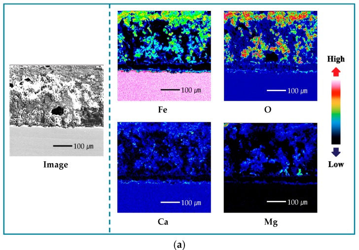
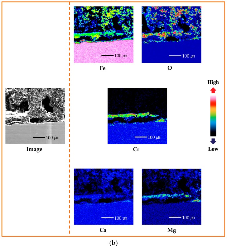
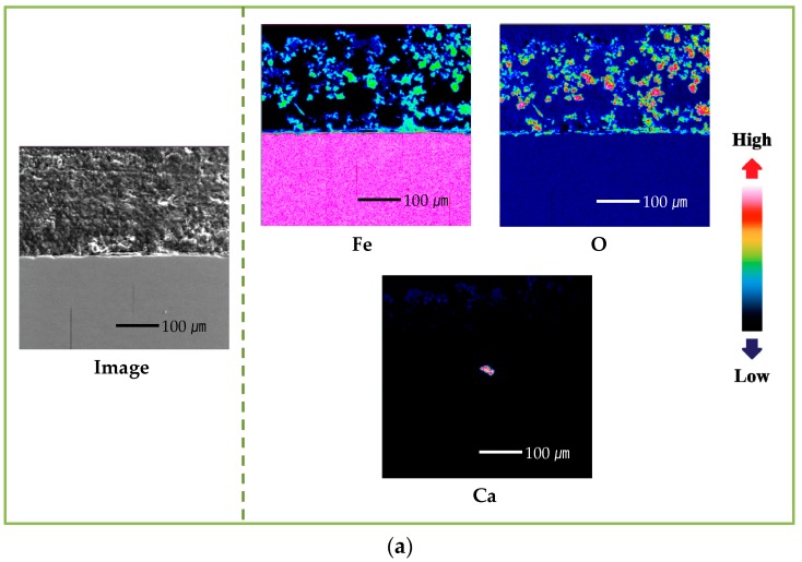
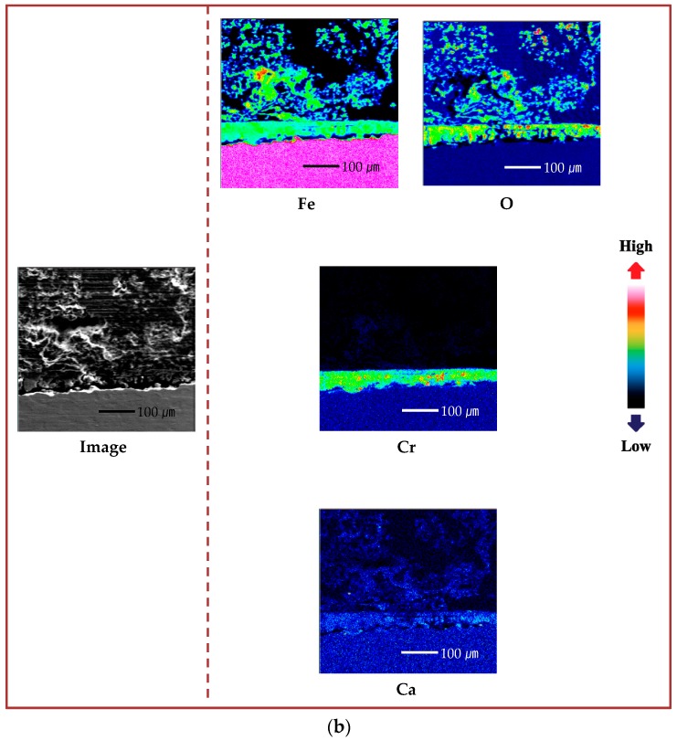
To identify the distribution and the concentration of the alloying elements, the rust layer of the specimens that were immersed in seawater for 30 days were analyzed using an electron probe microanalyzer (EPMA). Figure 1 shows the cross-sectional EPMA-mapping results for blank and Cr-alloying steels. The distribution of iron (Fe) is nonuniform, and the concentration is lower than that of the substrate, indicating that a part of the Fe in the rust layer had dissolved and the Fe-forming rust layer was produced by dissolution of the substrate. Also, the Fe in the Cr-alloying steel is distributed more closely to the substrate, compared with that of the blank steel. Due to the higher distribution and concentration of O compared with the substrate, oxide and hydroxide were formed in the rust layer. The localization of Cr in the rust layer near the substrate suggests that the alloying element, Cr, forms an enrichment layer, which is expected to improve corrosion resistance [21,22,23,27].
Figure 1.
Electron probe microanalyzer (EPMA) cross-sectional mapping results of specimens after 30 days immersion in seawater with Mg2+ ions: (a) blank steel and (b) 0.7-wt.%-Cr steel.
In regard to the seawater cation, Ca is distributed in the rust layers on both the blank- and 0.7-wt.%-Cr steel rust layers. Mg, however, showed a different trend in both of the specimens, as follows: It is distributed throughout the rust layer on the blank steel, but it is condensed in the 0.7-wt.%-Cr steel; furthermore, the concentrated-Mg region is included in the Cr-enrichment layer. From this result, it was expected that both the Mg and the Cr would contribute to the corrosion resistance. Thus, to identify the Cr–Mg synergic effect, the experiment was conducted in both the presence and the absence of the Cr-alloying element and the Mg2+ ions, in seawater.
2.2. Corrosion Rate Calculation
The corrosion rates of the specimens after 30 days of immersion were calculated using electrochemical impedance spectroscopy (EIS) and the linear polarization resistance (LPR) test. By fitting the EIS data and using the slopes of the potential and the current, the polarization resistance (Rp) can be obtained from the EIS and LPR data. Then, the Rp is transferred to the corrosion-current density, using the following equation [28]:
| (3) |
where and are the anodic and cathodic Tafel slopes, respectively, and icorr is the corrosion current density (μA/cm2). The impedance parameters of each specimen, including the Rp, are listed in Table 1. The corrosion rate can be determined from the icorr through Faraday’s law [28], as follows:
| (4) |
where M is the molar mass of the metal (g/mol), z is the number of transferred electrons per metal atom, F is Faraday’s constant, and ρ is the metal density (g/cm3).
Table 1.
EIS parameters of the specimens immersed in 60 °C seawater for 1 day and 30 days under an aerated condition.
| Specimen | Period | Rs (Ω∙cm2) | Constant Phase Element 1 | Rrust (Ω∙cm2) | Constant Phase Element 2 | RCr (Ω∙cm2) | Constant Phase Element 3 | Rct (Ω∙cm2) | Rp (Ω∙cm2) | |||
|---|---|---|---|---|---|---|---|---|---|---|---|---|
| Crust (F/cm2) | n (0–1) | CCr (F/cm2) | n (0–1) | Cdl (F/cm2) | n (0–1) | |||||||
| Blank steel (Seawater) |
1 day | 2.286 | - | - | - | - | - | - | 0.58 × 10⁻⁴ | 0.7818 | 400.9 | 400.9 |
| 30 days | 5.349 | 4.23 × 10⁻³ | 0.7643 | 30.51 | - | - | - | 28.20 × 10⁻³ | 0.4801 | 632.7 | 663.21 | |
| (α = 21.213) | ||||||||||||
| Blank steel (Mg2+ ions-free Seawater) |
1 day | 1.93 | - | - | - | - | - | - | 0.38 × 10⁻⁴ | 0.7991 | 406.6 | 406.6 |
| 30 days | 4.164 | 3.48 × 10⁻³ | 0.7463 | 23.26 | - | - | - | 13.76 × 10⁻³ | 0.5292 | 310.7 | 333.96 | |
| (α = 22.833) | ||||||||||||
| 0.7-wt.%-Cr steel (Seawater) |
1 day | 2.202 | - | - | - | - | - | - | 0.65 × 10⁻⁴ | 0.7806 | 420.7 | 420.7 |
| 30 days | 3.456 | 3.68 × 10⁻³ | 0.3949 | 3.64 | 0.68 × 10⁻³ | 0.8063 | 32.88 | 6.20 × 10⁻³ | 0.6321 | 769.3 | 805.82 | |
| (α = 17.433) | ||||||||||||
| 0.7-wt.%-Cr steel (Mg2+ ions-free Seawater) |
1 day | 2.077 | - | - | - | - | - | - | 0.75 × 10⁻⁴ | 0.7480 | 415.7 | 415.7 |
| 30 days | 5.563 | 1.59 × 10⁻³ | 0.5022 | 9.51 | 0.45 × 10⁻³ | 0.7646 | 55.95 | 1.19 × 10⁻³ | 0.7432 | 262.3 | 327.76 | |
| (α = 21.186) | ||||||||||||
Also, the weight loss-calculated corrosion rate was determined using the following equation [28]:
| (5) |
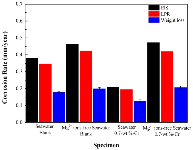
where 87,600 is the metric- and time-conversion factor, W is the weight loss (g), A is the exposure area (cm2), t is the immersion time (h), and ρ is the density (g/cm3). Figure 2 shows the corrosion rates of the blank and 0.7-wt.%-Cr steels after the 30-day immersion in seawater, with and without the Mg2+ ions. The corrosion rates calculated by EIS, LPR, and weight loss tests showed the similar trend in all three experiments: The average corrosion rates of the steels decreased in the following order: 0.7-wt.%-Cr steel without the Mg2+ ions ≈ blank steel without the Mg2+ ions > blank steel with the Mg2+ ions > 0.7-wt.%-Cr steel with the Mg2+ ions. This result shows that the Cr-alloying element only improved the corrosion resistance in the seawater containing the Mg2+ ions. The difference in the corrosion rates of the blank steel, in the presence and absence of the Mg2+-containing seawater, is due to the Mg(OH)2 that acts as a physical barrier. In the 0.7-wt.%-Cr steel, the difference in corrosion rate between the Mg2+-containing and Mg2+-free seawater solutions is larger than that of the blank steel, which can be explained by not only the Mg2+-containing effect, but also the barrier effect between the Mg2+, Fe2+, and Cr3+ ions. As shown in Figure 1b, it is expected that the Mg2+, Fe2+, and Cr3+ ions that are concentrated near the substrate will form a compound and act as a barrier against corrosion.
Figure 2.
Corrosion rates of specimens, measured by electrochemical impedance spectroscopy (EIS), linear polarization resistance (LPR) and weight-loss measurements for 30 days.
2.3. Electrochemical Impedance Spectroscopy (EIS)
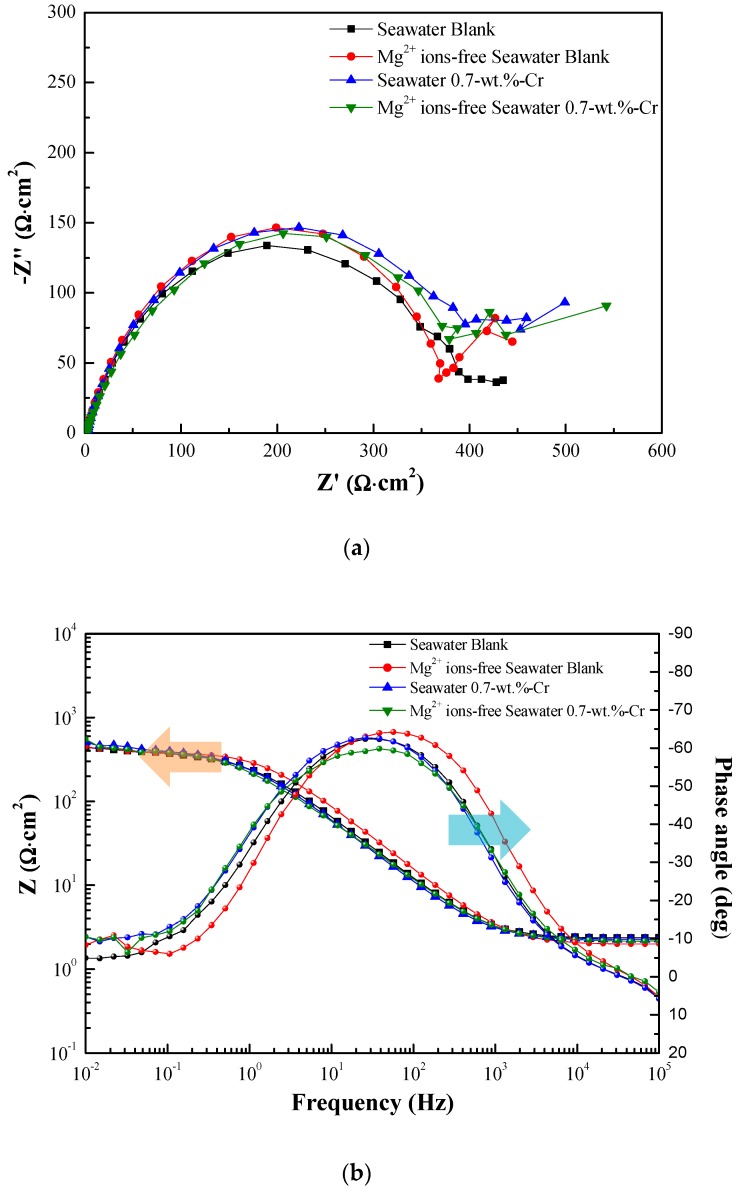
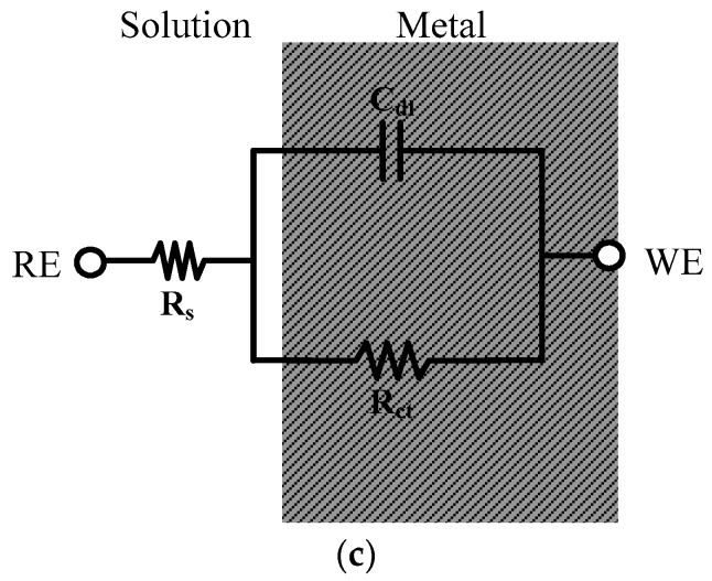
The Nyquist and Bode plots of the specimens after 1 day of immersion are shown in Figure 3a,b. Since the formation of the rust layer is insignificant, the impedance results can be fitted to the circuit model that is shown in Figure 3c, as one time constant, and the impedance parameters that are listed in Table 1.
Figure 3.
Impedance spectra data of specimens immersed in 60 °C seawater for 1 day: (a) Nyquist plots, (b) Bode plots and (c) equivalent circuit.
The equivalent circuit consists of the following elements: Rs represents the solution resistance, Cdl is the capacitance that is generated by the electric double layer, and Rct is the charge-transfer resistance. The RE is the reference electrode (saturated calomel electrode), and WE is the working electrode (specimens). The experiment results show that the Rp values are similar, regardless of the presence of the Cr-alloying element and the Mg2+ ions in the seawater.
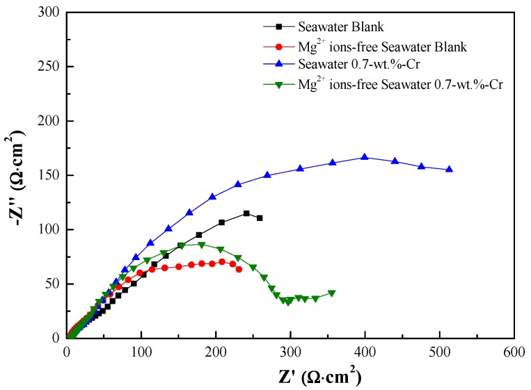
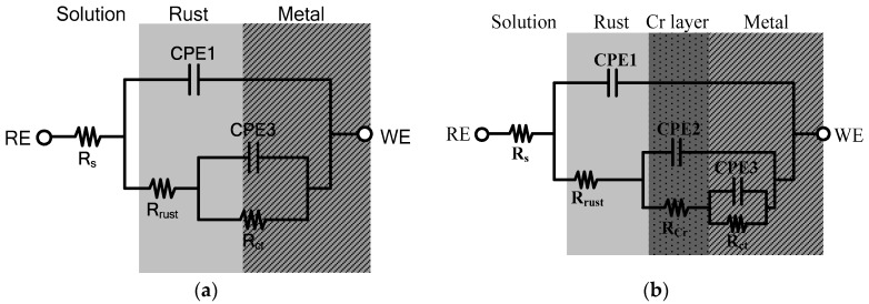
Also, the Nyquist plot impedance spectra after the 30 days of immersion are shown in Figure 4. According to the different rust layers, the equivalent electrical circuits were used to fit the results of the EIS tests, as shown in Figure 1. Figure 5 shows each of the equivalent electrical circuits of the blank and 0.7-wt.%-Cr steels. Due to the Cr-enrichment layer, the spectra of the 0.7-wt.%-Cr steel exhibited a three-time constant, while the blank steel exhibited a two-time constant. The equivalent circuit consists of the following elements: Rs represents the solution resistance, Crust is the rust capacitance, Rrust is the rust resistance, Cdl is the capacitance that is generated by the electric double layer, and Rct is the charge-transfer resistance. The RE is the reference electrode (saturated calomel electrode), and WE is the working electrode (specimens). Also, CCr is the capacitance that is formed by the Cr-enrichment layer and RCr is the Cr-enrichment-layer resistance. In this instance, the capacitors were replaced with the constant phase elements (CPEs) for more accurate EIS-data fitting, where not only a double layer capacitance (C) but also a phenomenological coefficient (n) have been included. The CPE impedance takes the following form:
| (6) |
where Q is an effective CPE coefficient, ω is the sine-wave-modulation angular frequency, j is an imaginary number, and n is the phenomenological coefficient that characterizes the phase shift [29,30,31,32]. Thus, in this paper, Crust, CCr, and Cdl were replaced with CPE1, CPE2, and CPE3, respectively.
Figure 4.
Nyquist plots for specimens immersed in 60 °C seawater for 30 days.
Figure 5.
Equivalent circuit models for interpretation of the impedance spectra after 30 days: (a) blank steel and (b) 0.7-wt.%-Cr steel.
In the Nyquist plot, the degree of depression of the semicircle, with a center below the real axis, determines the depression angle (α). The depression angle is an empirical factor that represents the deviation from the ideal capacity [33,34]. The increase in the depression angle means there is an increase in surface inhomogeneity, due to surface roughness and layer porosity [35,36]. The depression angle that is calculated by the following equation is associated with the phenomenological coefficient (n) [29,32,33]:
| (7) |
Table 1 lists the fitted EIS data from the 1-day and 30-day immersions, which determined the optimized values that were obtained using the ZSimpwin program (Princeton Applied Research, USA), according to each of the equivalent electrical circuits in Figure 5 [37,38]. The total polarization resistance (Rp) that is represented in Table 1 is equal to Rrust + Rct for the blank steel and Rrust + RCr + Rct for the 0.7-wt.%-Cr steel. In the 0.7-wt.%-Cr steel, the calculated depression-angle value of the Mg2+-containing seawater specimen is 17.433° and that of the Mg2+-free specimen is 21.186°. This result means that the characteristics of the Cr-enrichment layers that formed on both specimens are different, as follows: The 0.7-wt.%-Cr steel with the Mg2+ ions comprises a dense layer compared with that without the Mg2+ ions. Also, the depression-angle values of the blank steel are 21.213° and 22.833°, with and without the Mg2+ ions, respectively. This porosity difference, regarding the rust layer, is due to the physical barrier that is caused by the Mg2+ ions in the seawater, which also causes the corrosion rate difference for the blank steel.
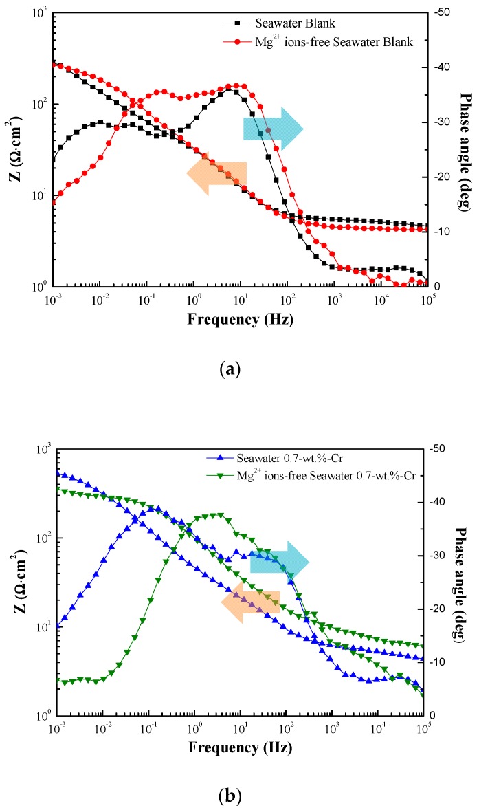
Figure 6 shows the EIS Bode plots of the blank and 0.7-wt.%-Cr steels, with and without the Mg2+ ions, for the 30-day immersion in the synthetic seawater at 60 °C. The splitting of the phase angle frequency curve indicates the presence of other phases.
Figure 6.
Bode plots for the specimens immersed in 60 °C seawater for 30 days. Specimens are (a) blank steels, with and without Mg2+ ions and (b) 0.7-wt.%-Cr steels with and without Mg2+ ions. The splitting of the phase angle to lower frequency means the change of capacitance.
In Figure 6, each of the split shoulders on the phase angle are shifted to the lower frequency, compared with the Mg2+-free seawater, meaning that the capacitance values of the Mg2+-containing seawater are larger, as identified in Table 1. In the blank steel, the Crust value is larger in the Mg2+-containing seawater. Because the capacitance is inversely proportional to the thickness, the rust layer in the Mg2+-free seawater is thicker, due to the greater corrosion. Also, the Cdl value, which is formed as the ions are absorbed onto the electrode surface, is larger in the Mg2+-containing seawater. Thus, the different values are reasonable because the Mg2+-containing seawater comprises a higher quantity of adsorbable ions. In the 0.7-wt.%-Cr steel, the capacitance values—Crust, CCr, and Cdl—are larger in the Mg2+-containing seawater. The Crust that represents the rust layer thickness shows the formation of a thin rust layer, due to the lower level of corrosion. The Cdl difference can be associated with ion absorption due to the Mg2+ ions in the seawater. The Cdl values between the blank and 0.7-wt.%-Cr steels, however, indicate a significant difference. This phenomenon means that the Cr-enrichment layer interrupts ionic absorption on the metal surface. Here, the CCr, the thickness of the Cr-enrichment layer, represents the production of a thin Cr-enrichment layer in the Mg2+-containing seawater that is identified by the detected Cr element in Figure 1b and Figure 6b. The Rct is a resistance value that prevents electron transfer from the metal layer to the rust layer, thereby indicating its relation to the metal corrosion rate. The larger Rct values of the blank and 0.7-wt.%-Cr steels in the Mg2+-containing seawater indicate the suppression of the electron transfer compared with the Mg2+-free seawater.
2.4. Surface Analysis
Figure 7 shows the cross-sectional EPMA-mapping results for the Mg2+-free seawater during the 30-day immersion. The tendencies, distributions, and concentrations of the Fe, oxygen (O), and Cr between the rust layer and the substrate are similar to those of the Mg2+-containing seawater, as shown in Figure 1. The 0.7-wt.%-Cr steel, with and without the Mg2+ ions, represents the Cr-enrichment layer, and the average thicknesses are approximately 25 μm and 45 μm, respectively. The Cr-enrichment layers are produced by the corrosion of the specimens, and the Cr3+ ions are redeposited onto the steel surface through reduction reactions [39]. Thus, the thicker thickness of the Cr-enrichment layer without the Mg2+ environment means that more corrosion occurred on the steel surface. This result means that the corrosion rate is more affected by the porosity than the thickness of the Cr-enrichment layer. The Rp values that were measured at the 1- and 30-day immersions, which are shown in Table 1, indicate that the rust layer porosity affects the corrosion rate. In the Mg2+-containing seawater environment, both the blank and 0.7-wt.%-Cr steels increased the Rp over time, whereas the Rp decreased for both of the specimens in the Mg2+-free-seawater environment; this is because the base steel corrosion continues through the porous region of the rust layer.
Figure 7.
EPMA cross-sectional mapping results of specimens after 30 days immersion in seawater without Mg2+ ions: (a) blank steel and (b) 0.7-wt.%-Cr steel.
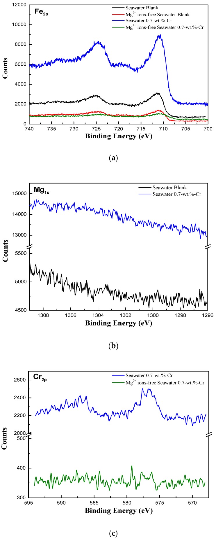
To determine the chemical composition of the corrosion product after the 30-day immersion test, X-ray photoelectron spectroscopy (XPS) and X-ray diffraction (XRD) measurements were carried out. The local area near the Cr-enrichment layer was detected using XPS with the cross-section specimen, and the whole area was detected by XRD with a top-view specimen. Figure 8 shows the XPS spectra of the specimens. The Fe peaks were commonly found in all of the specimens, but the Mg and Cr peaks appeared in accordance with the experimental environment and the alloying element. The steel surface products that were obtained from the analysis of the XPS peaks are listed in Table 2. In Figure 8a, a proportional relationship is evident between the intensity values of the chemical compounds, such as magnetite (Fe3O4), iron(III) oxide (Fe2O3), and iron hydroxide (FeOOH), and the corrosion resistance. The increase in the amount of the Fe oxide products resulted in an enhanced corrosion resistance because the Fe oxide products act as the corrosion protection layer of the steels [34,40]. Similarly, in Figure 8b,c, the high intensity values of the Mg and Cr peaks mean that the effects of the Mg and Cr barriers react more significantly on the 0.7-wt.%-Cr steel in seawater. The difference in the intensity value is due to not only the amounts of the Mg(OH)2, chromium(III) oxide (Cr2O3), chromium hydroxide (CrOOH), and iron(II) chromite (FeCr2O4), but it is also owing to the formation of Mg and the Cr-containing product, magnesium(II) chromite (MgCr2O4). MgCr2O4, the structure of which is spinel, is known for its corrosion resistance improvement property [41,42,43,44]. It also acts as a p-type-semiconductor corrosive film that prevents the corrosion reaction [45]. Thus, the formation of MgCr2O4 increases the corrosion resistance of the 0.7-wt.%-Cr steel in seawater.
Figure 8.
XPS spectra for the cross-sectional products of the specimens after 30 days immersion according to seawater conditions and alloying elements: (a) Fe, (b) Mg and (c) Cr.
Table 2.
Analysis of the XPS peaks for the surface of the specimens.
| Analyses of the XPS Spectra | Product | Binding Energy (eV) |
|---|---|---|
| Spectrum of Fe2p | FeOOH | 711.5, 724.3 |
| Fe2O3 | 711.0, 724.0, 710.8 | |
| Fe3O4 (Fe2+) | 708.3 | |
| Fe3O4 (Fe3+) | 710.2 | |
| Spectrum of Mg1s | Mg(OH)2 | 1302.7 |
| MgO | 1303.9 | |
| Spectrum of Cr2p | Cr2O3 | 576.5, 576.8, 587.4 |
| CrOOH | 576.8, 577 | |
| FeCr2O4 | 576.0 | |
| MgCr2O4 | 576.4 |
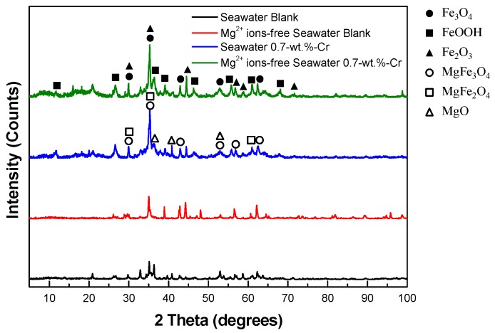
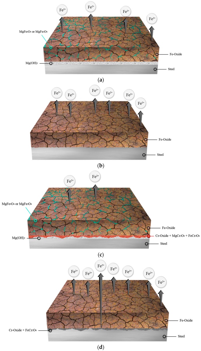
The XRD spectra of the specimens are shown in Figure 9. The Fe corrosion products show the same XPS results, but the other corrosion products, such as magnesium magnetite (MgFe3O4) and magnesium iron oxide (MgFe2O4), which are not shown in the XPS data, were detected. Wang et al. [46] reported that the existence of MgFe2O4 in the rust layer exerts a protective effect on weathering steel. Also, since the structure of MgFe2O4 is spinel, like that of MgCr2O4, this improves the corrosion resistance. The MgFe2O4 acts as an n-type-semiconductor corrosive film that works as a cation-selective rust layer [42,47,48]. Based on the surface analysis, the schematic diagrams of the corrosion products that affect the corrosion property are represented in Figure 10. Due to the corrosion barriers, such as MgFe3O4, the MgFe2O4 with Fe oxide, Cr oxide, FeCr2O4, and Mg(OH)2, the corrosion resistance of the 0.7-wt.%-Cr steel is the highest in seawater. In particular, for the 0.7-wt.%-Cr steel in seawater, the Cr oxide, FeCr2O4, and MgCr2O4 mixed layers contributed to the enhancement of the corrosion resistance. The corrosion resistance of the blank steel in seawater is the second highest, due to the MgFe3O4, the MgFe2O4 with Fe oxide, and Mg(OH)2. The corrosion resistance of the blank steel in the Mg2+-free seawater, which only comprises an Fe oxide corrosion barrier, is lower. Although the 0.7-wt.%-Cr steel in the Mg2+-free seawater consists of Fe oxide, Cr oxide, and FeCr2O4 barriers, the corrosion resistance is similar to that of the blank steel under the same seawater conditions. This phenomenon is due to the less-protective Cr oxide and FeCr2O4 layers and the galvanic-corrosion effect. On the steel surface, the Cr oxide and FeCr2O4 layers without the MgCr2O4 comprise the porosity property, as shown in the EIS results. Also, since the Cr oxide and the FeCr2O4 do not cover the steel surface perfectly, the Cr oxide behaves as the large cathode and the bare-steel surface behaves as the small anode. Thus, the large ratio of the cathode-to-anode surface area accelerated the galvanic-reaction corrosion of the 0.7-wt.%-Cr steel [28].
Figure 9.
XRD spectra for the top-view products of specimens after 30 days immersion according to seawater conditions and alloying elements.
Figure 10.
Schematic diagrams of corrosion products on specimens after 30 days immersion in seawater: (a) blank steel in seawater; (b) blank steel in Mg2+ ions-free seawater; (c) 0.7-wt.%-Cr steel in seawater and (d) 0.7-wt.%-Cr steel in Mg2+ ion-free seawater.
3. Materials and Methods
3.1. Materials and Test Condition
Table 3 summarizes the chemical compositions of the low-alloy steels that were used in the experiment. The specimens were produced by a thermomechanical control process (TMCP), which is a widely applied process for offshore structures and vessels, because of its superior mechanical properties, whereby both the rolling and cooling conditions are controlled [49,50,51]. Since the low-alloy steel is produced by vacuum melting, there is no contamination from the surroundings and the gas content of the steel is low. In addition, since the low-alloy steels were produced in small quantities to improve the product quality, the alloying elements were evenly distributed at the time of production. The plate of the low-alloy steels was cut into pieces of approximately 1 × 1 × 1.5 cm. The specimens were abraded with silicon carbide (SiC) papers, with grit sizes from 60 to 600, followed by rinsing with ethanol and distilled water, and finally drying was performed with a drying machine. The prepared specimen was immersed in the synthetic seawater at 60 °C and a pH of 8.2, under aerated conditions for 30 days; this temperature was selected because the inner part of the WBT can be reached by solar heat up to 60 °C [27,52]. The synthetic seawater solution was prepared based on the American Society for Testing and Materials (ASTM) standard D1141 [53]. Magnesium chloride (MgCl2) was excluded from the D1141 standard for the preparation of the Mg2+-free seawater, and the chlorine (Cl) concentration was adjusted with sodium chloride (NaCl).
Table 3.
Chemical compositions of low-alloy steels (wt.%).
| Specimen | Fe | C | Si | Mn | P | S | Nb | Ti | Cr |
|---|---|---|---|---|---|---|---|---|---|
| Blank steel | Balance | 0.07 | 0.3 | 1 | 0.012 | 0.003 | 0.01 | 0.015 | - |
| 0.7-wt.%-Cr steel | Balance | 0.07 | 0.3 | 1 | 0.012 | 0.003 | 0.01 | 0.015 | 0.7 |
3.2. Electrochemical Test
The EIS analysis and the LPR test were performed using the EG&G PAR VMP2 potentiostat/galvanostat (Princeton Applied Research, VMP2 & VMP2/Z multichannel potentiostats, BioLogic science instruments, Knoxville, TN, USA). To perform the electrochemical tests, the three-electrode electrochemical system consists of a low-alloy steel, two pure graphites, and a saturated calomel electrode (SCE) that served as the working, counter, and reference electrodes, respectively. The EIS analysis was carried out to calculate the corrosion rate and to observe the change in the rust layer with an amplitude of 10 mV, at frequencies ranging from 100 kHz to 1 mHz (or 10 mHz in the 1-day case). With the use of the Zsimpwin software (v3.2, Princeton Applied Research, Oak Ridge, TN, USA), the impedance plots were interpreted on the basis of the equivalent circuit, according to a suitable fitting procedure. The LPR tests were carried out at a potential sweep of 0.166 mV/s, from an initial potential of −20 mVocp, to a final potential of 20 mVocp. The polarization resistance was obtained from the slope of the potential versus the current-density curve.
3.3. Weight-Loss Test
Weight-loss measurements were performed according to the ASTM standard, G31 [54]. The lengths of three sides of rectangular specimens were measured up to two decimals. Every specimen was immersed in the synthetic seawater after a plastic wire hanging. After the immersion period of 30 days, the specimens were removed and then cleaned with a 10-min immersion in a 1000-mL solution that was composed of 3.5 g of hexamethylene tetramine (C6H12N4), 500 mL of hydrogen chloride (HCl), and balanced distilled water. These specimens were also degreased for 10 min in an ultrasonic cleaner with ethanol, followed by cleaning with distilled water and drying with N2, and then their final mass was measured to four decimal places. To improve the reliability, this experiment was performed repetitively in triplicate.
3.4. Surface Analysis
To investigate the effect of Cr and the relationship between Cr and the seawater cation, a surface analysis was carried out. The corroded surface features after the 30-day immersion in the 60 °C synthetic seawater, depending on the solution states, were observed using the JXA-8900R EPMA (JEOL, Tokyo, Japan). The chemical composition of the rust layer was identified using the ESCALAB 250 XPS instrument (Thermo Fisher Scientific, Waltham, MA, USA) with a monochromatic Al-Kα energy source and the D/Max 2500 V PC XRD instrument (Rigaku Corporation, Tokyo, Japan) with a scan rate of 3°/min from 5–100°.
4. Conclusions
This study investigated the synergic effect of the alloying element, Cr, and the environment element, Mg2+, on the corrosion of low-alloy steels in synthetic seawater at 60 °C, using EIS, LPR tests, weight-loss tests, and a surface analysis. Based on the previously presented results, the following conclusions can be drawn:
From the EPMA results in the seawater, the 0.7-wt.%-Cr steel represents the Cr-enrichment layer, and the Mg2+ ions in the seawater are also concentrated on the Cr-enrichment layer.
The EIS analysis, LPR tests, and weight-loss tests, with and without the Cr-alloying element and the Mg2+-containing seawater, revealed the following order for the average corrosion rates of the steels: 0.7-wt.%-Cr steel without the Mg2+ ions ≈ blank steel without the Mg2+ ions > blank steel with the Mg2+ ions > 0.7-wt.%-Cr steel with the Mg2+ ions. The Cr-alloying element only improved corrosion resistance in the Mg2+-containing seawater, and the reason is not only the Mg2+-containing effect, but also the barrier effect between the Mg2+, Fe2+, and Cr3+ ions.
The EIS interpretation of the blank and 0.7-wt.%-Cr steels suggests that both of the steels under the seawater condition show a rust layer, with a relatively nonporous corrosion on the steel surface.
The XPS and XRD analyses showed that the rust layer of the 0.7-wt.%-Cr steel in the seawater comprises effective protection barriers, such as MgFe3O4, MgFe2O4, MgCr2O4 with Fe oxide, Cr oxide, FeCr2O4, and Mg(OH)2. Also, the high-porosity condition of the Cr oxide layer was changed to a low-porosity condition.
Author Contributions
Jung-Gu Kim conceived and designed the experiments; Sol-Ji Song performed the experiments; Jung-Gu Kim and Sol-Ji Song analyzed the data; Jung-Gu Kim contributed reagents/materials/analysis tools; Sol-Ji Song wrote the paper.
Conflicts of Interest
The authors declare no conflict of interest.
References
- 1.David M., Gollash S. Global Maritime Transport and Ballast Water Management. Volume 8. Springer Science; Dordrecht, The Netherlands: 2015. [Google Scholar]
- 2.Prange G.J., Pereira N.N. Ship ballast tank sediment reduction methods. Nav. Eng. J. 2013;125:127–134. [Google Scholar]
- 3.Goncalves A.A., Gagnon G.A. Recent technologies for ballast water treatment. Ozone Sci. Eng. 2012;34:174–195. doi: 10.1080/01919512.2012.663708. [DOI] [Google Scholar]
- 4.Soares C.G., Garbatov Y., Zayed A., Wang G. Influence of environmental factors on corrosion of ship structures in marine atmosphere. Corros. Sci. 2009;51:2014–2026. doi: 10.1016/j.corsci.2009.05.028. [DOI] [Google Scholar]
- 5.Nanayakkara K.G.N., Zheng Y.M., Alam A.K.M.K., Zou S., Chen J.P. Electrochemical disinfection for ballast water management: Technology development and risk assessment. Mar. Pollut. Bull. 2011;63:119–123. doi: 10.1016/j.marpolbul.2011.03.003. [DOI] [PubMed] [Google Scholar]
- 6.Kim S.J., Lee S.J. Anticorrosion characteristics of a Zn-primer coating in a ballast tank under various chloride concentrations. Phys. Scr. 2010;T139:1–4. doi: 10.1088/0031-8949/2010/T139/014034. [DOI] [Google Scholar]
- 7.Melchers R.E., Jiang X. Estimation of models for durability of epoxy coatings in water ballast tanks. Ships Offshore Struct. 2006;1:61–70. doi: 10.1533/saos.2004.0006. [DOI] [Google Scholar]
- 8.Lee D.G., Kim B.C. Investigation of coating failure on the surface of a water ballast tank of an oil tanker. J. Adhes. Sci. Technol. 2005;19:879–908. doi: 10.1163/1568561054929946. [DOI] [Google Scholar]
- 9.Sorensen P.A., Kiil S., Johansen K.D., Weinell C.E. Anticorrosive coatings: A review. J. Coat. Technol. Res. 2009;6:135–176. doi: 10.1007/s11998-008-9144-2. [DOI] [Google Scholar]
- 10.Baere K.D., Verstraelen H., Rigo P., Passel S.V., Lenaerts S., Potters G. Study on alternative approaches to corrosion protection of ballast tanks using an economic model. Mar. Struct. 2013;32:1–17. doi: 10.1016/j.marstruc.2013.02.003. [DOI] [Google Scholar]
- 11.Heyer A., D’Souza F., Zhang X., Ferrari G., Mol J.M.C., de Wit J.H.W. Biodegradation of ballast tank coating investigated by impedance spectroscopy and microscopy. Biodegradation. 2014;25:67–83. doi: 10.1007/s10532-013-9641-6. [DOI] [PubMed] [Google Scholar]
- 12.Hou B., Li Y., Li Y., Zhang J. Effect of alloy elements on the anti-corrosion properties of low alloy steel. Bull. Mater. Sci. 2000;23:189–192. doi: 10.1007/BF02719908. [DOI] [Google Scholar]
- 13.Melchers R.E. Effect on marine immersion corrosion of carbon content of low alloy steels. Corros. Sci. 2003;45:2609–2625. doi: 10.1016/S0010-938X(03)00068-4. [DOI] [Google Scholar]
- 14.Zhou Y., Chen J., Xu Y., Liu Z. Effects of Cr, Ni and Cu on the corrosion behavior of low carbon microalloying steel in a Cl− containing environment. J. Mater. Sci. Technol. 2013;29:168–174. doi: 10.1016/j.jmst.2012.12.013. [DOI] [Google Scholar]
- 15.Schultze W.A., Wekken C.V.D. Influence of alloying elements on the marine corrosion of low alloy steels determined by statistical analysis of published literature data. Br. Corros. J. 1976;11:18–24. doi: 10.1179/bcj.1976.11.1.18. [DOI] [Google Scholar]
- 16.Fozan S.A.A., Malik A.U. Effect of seawater level on corrosion behavior of different alloys. Desalination. 2008;228:61–67. doi: 10.1016/j.desal.2007.08.007. [DOI] [Google Scholar]
- 17.Melchers R.E. Effect of small compositional changes on marine immersion corrosion of low alloy steels. Corros. Sci. 2004;46:1669–1691. doi: 10.1016/j.corsci.2003.10.004. [DOI] [Google Scholar]
- 18.Nishimura T., Tahara A., Kodama T. Effect of Al on the corrosion behavior of low alloy steels in wet/dry environment. Mater. Trans. 2001;42:478–483. doi: 10.2320/matertrans.42.478. [DOI] [Google Scholar]
- 19.Nishimura T., Katayama H., Noda K., Kodama T. Effect of Co and Ni on the corrosion behavior of low alloy steels in wet/dry environment. Corros. Sci. 2000;42:1611–1621. doi: 10.1016/S0010-938X(00)00018-4. [DOI] [Google Scholar]
- 20.Chen X., Dong J., Han E., Ke W. Effect of Ni on the ion-selectivity of rust layer on low alloy steel. Mater. Lett. 2007;61:4050–4053. doi: 10.1016/j.matlet.2007.01.014. [DOI] [Google Scholar]
- 21.Blekkenhorst F., Ferrari G.M., Wekken C.V.D., Ijsseling F.P. Development of high strength low alloy steels for marine applications: Part 1: Results of long term exposure tests on commercially available and experimental steels. Br. Corros. J. 1986;21:163–176. doi: 10.1179/000705986798272136. [DOI] [Google Scholar]
- 22.Zhang Q.C., Wu J.S., Wang J.J., Zheng W.L., Chen J.G., Li A.B. Corrosion behavior of weathering steel in marine atmosphere. Mater. Chem. Phys. 2002;77:603–608. doi: 10.1016/S0254-0584(02)00110-4. [DOI] [Google Scholar]
- 23.Yamashita M., Konishi H., Mizuki J., Uchida H. Nanostructure of protective rust layer on weathering steel examined using synchrotron radiation X-rays. Mater. Trans. 2004;45:1920–1924. doi: 10.2320/matertrans.45.1920. [DOI] [Google Scholar]
- 24.Moller H., Boshoff E.T., Froneman H. The corrosion behavior of a low carbon steel in natural and synthetic seawaters. J. S. Afr. Inst. Min. Metall. 2006;106:585–592. [Google Scholar]
- 25.Cottis R.A., Graham M.J., Lindsay R., Lyon S.B., Richardson J.A., Scantlebury J.D., Stott F.H. Shreir’s Corrosion. Volume 2. Elsevier; Amsterdam, The Netherlands: 2010. [Google Scholar]
- 26.Wolfson S.L., Hartt W.H. An initial investigation of calcareous deposits upon cathodic steel surface in seawater. Corrosion. 1981;37:70–76. doi: 10.5006/1.3593848. [DOI] [Google Scholar]
- 27.Kim D.W., Kim H.S. Effects of alloying elements on corrosion resistance of low alloyed steels in a seawater ballast tank environment. Korean J. Met. Mater. 2010;48:523–532. doi: 10.3365/KJMM.2010.48.06.523. [DOI] [Google Scholar]
- 28.Jones D.A. Principles and Prevention of Corrosion. 2nd ed. Prentice-Hall; Upper Saddle River, NJ, USA: 1996. [Google Scholar]
- 29.Lvovivh V.F. Impedance Spectroscopy: Applications to Electrochemical and Dielectric Phenomena. Wiley; Hoboken, NJ, USA: 2012. [Google Scholar]
- 30.Bentissa F., Lebrini M., Vezin H., Chai F., Traisnel M., Lagrene M. Enhanced corrosion resistance of carbon steel in normal sulfuric acid medium by some macrocyclic polyether compounds containing a 1,3,4-thiadiazole moiety: AC impedance and computational studies. Corros. Sci. 2009;51:2165–2173. doi: 10.1016/j.corsci.2009.05.049. [DOI] [Google Scholar]
- 31.Nam N.D., Kim J.G. Effect of niobium on the corrosion behavior of low alloy steel in sulfuric acid solution. Corros. Sci. 2010;52:3377–3384. doi: 10.1016/j.corsci.2010.06.010. [DOI] [Google Scholar]
- 32.Yuan X.Z., Song C., Wang H., Zhang J. Electrochemical Impedance Spectroscopy in PEM Fuel Cells: Fundamentals and Applications. Springer; New York, NY, USA: 2010. [Google Scholar]
- 33.Roberge P.R., Halliop E., Sastri V.S. Corrosion of mild steel using electrochemical impedance spectroscopy data analysis. Corrosion. 1992;48:447–454. doi: 10.5006/1.3315959. [DOI] [Google Scholar]
- 34.Lee D.Y., Kim W.C., Kim J.G. Effect of nitrite concentration on the corrosion behavior of carbon steel pipelines in synthetic tap water. Corros. Sci. 2012;64:105–114. doi: 10.1016/j.corsci.2012.07.005. [DOI] [Google Scholar]
- 35.Lebrini M., Lagrenée M., Vezin H., Traisnel M., Bentiss F. Experimental and theoretical study for corrosion inhibition of mild steel in normal hydrochloric acid solution by some new macrocyclic polyether compounds. Corros. Sci. 2007;49:2254–2269. doi: 10.1016/j.corsci.2006.10.029. [DOI] [Google Scholar]
- 36.Flis J., Pickering H.W., Osseo-Asare K. Interpretation of impedance data for reinforcing steel in alkaline solution containing chlorides and acetates. Electrochem. Acta. 1998;43:1921–1929. doi: 10.1016/S0013-4686(97)10004-4. [DOI] [Google Scholar]
- 37.Hong S.J., Lee S., Jang J.S., Lee J.S. Heterojunction BiVO4/WO3 electrodes for enhanced photoactivity of water oxidation. Energy Environ. Sci. 2011;4:1781–1787. doi: 10.1039/c0ee00743a. [DOI] [Google Scholar]
- 38.Yin Z.F., Zhao W.Z., Lai W.Y., Zhao X.H. Electrochemical behaviour of Ni-base alloys exposed under oil/gas filed environments. Corros. Sci. 2009;51:1702–1706. doi: 10.1016/j.corsci.2009.04.019. [DOI] [Google Scholar]
- 39.Park S.A., Ji W.S., Kim J.G. Effect of chromium on the corrosion behavior of low-alloy steels containing copper in FGD environment. Int. J. Electrochem. Sci. 2013;8:7498–7509. doi: 10.1007/s12540-012-6009-0. [DOI] [Google Scholar]
- 40.Cook D.C., Oh S.J., Balasubramanian R., Yamashita M. The role of goethite in the formation of the protective corrosion layer on steels. Hyperfine Interact. 1999;122:59–70. doi: 10.1023/A:1012685320582. [DOI] [Google Scholar]
- 41.Palanna O.G. Engineering Chemistry. McGraw Hill; New Delhi, India: 2009. [Google Scholar]
- 42.Shreir L.L. Corrosion: Metal/Environment Reactions. Volume 1. Newnes-Butterworths; London, UK: Boston, MA, USA: 1976. [Google Scholar]
- 43.Fernández A.G., Pérez F.J. Improvement of the corrosion properties in ternary molten nitrate salts for direct energy storage in CSP plants. Sol. Energy. 2016;134:468–478. doi: 10.1016/j.solener.2016.05.030. [DOI] [Google Scholar]
- 44.Hon M.H., Hsu C.C., Wang M.C. Corrosion of magnesia-chrome brick in molten MgO-Al2O3-SiO2-CaO-FetO slag. Mater. Chem. Phys. 2008;110:247–255. doi: 10.1016/j.matchemphys.2008.02.001. [DOI] [Google Scholar]
- 45.Craig B.D. Fundamental Aspects of Corrosion Films in Corrosion Science. Plenum Press; New York, NY, USA: 1991. [Google Scholar]
- 46.Wang J., Wang Z.Y., Ke W. Corrosion behaviour of weathering steel in diluted Qinghai salt lake water in a laboratory accelerated test that involved cyclic wet/dry conditions. Mater. Chem. Phys. 2010;124:952–958. doi: 10.1016/j.matchemphys.2010.07.069. [DOI] [Google Scholar]
- 47.Sato N. Basic of Corrosion Chemistry. In: Sharma S.K., editor. Green Corrosion Chemistry and Engineering. Wiley; Weinheim, Germany: 2012. pp. 19–24. [Google Scholar]
- 48.Fujimoto S., Tsuchiya H. Semiconductor Property of Passive Films and Corrosion Behavior of Fe-Cr Alloys. In: Waseda Y., Suzuki S., editors. Characterization of Corrosion Products on Steel Surfaces. Springer; New York, NY, USA: 2006. pp. 33–50. [Google Scholar]
- 49.Nobuo S., Shinji M., Shigeru E. Recent development in microstructural control technologies through the thermo-mechanical control process (TMCP) with JFE Steel’s high-performance plates. JFE Tech. Rep. 2008;11:1–6. [Google Scholar]
- 50.Yanchun L., Fuxian Z., Yanmei L., Guodong W. Effect of TMCP parameters on the microstructure and properties of an Nb-Ti microalloyed steel. ISIJ Int. 2005;45:851–857. doi: 10.2355/isijinternational.45.851. [DOI] [Google Scholar]
- 51.Imai S. General properties of TMCP steels; Proceedings of the Twelfth International Offshore and Polar Engineering Conference; Kitakyushu, Japan. 26–31 May 2002; Cupertino, CA, USA: International Society of Offshore and Polar Engineers (ISOPE); 2002. pp. 392–396. [Google Scholar]
- 52.Paik J.K. Corrosion analysis of seawater ballast tank structures. Int. J. Marit. Eng. 2004;146:1–12. doi: 10.3940/rina.ijme.2004.a1.804. [DOI] [Google Scholar]
- 53.ASTM D1141-98: Standard Practice for the Preparation of Substitute Ocean Water. ASTM Inernational; West Conshohocken, PA, USA: 2013. [Google Scholar]
- 54.ASTM G31-72: Standard Practice for Laboratory Immersion Corrosion Testing of Metals. ASTM Inernational; West Conshohocken, PA, USA: 2002. [Google Scholar]


