Abstract
The prominent advantage of meshfree method, is the way to build the representation of computational domain, based on the nodal points without any explicit meshing connectivity. Therefore, meshfree method can conveniently process the numerical computation inside interested domains with large deformation or inhomogeneity. In this paper, we adopt the idea of meshfree representation into cardiac medical image analysis in order to overcome the difficulties caused by large deformation and inhomogeneous materials of the heart. In our implementation, as element-free Galerkin method can efficiently build a meshfree representation using its shape function with moving least square fitting, we apply this meshfree method to handle large deformation or inhomogeneity for solving cardiac segmentation and motion tracking problems. We evaluate the performance of meshfree representation on a synthetic heart data and an in-vivo cardiac MRI image sequence. Results showed that the error of our framework against the ground truth was 0.1189 ± 0.0672 while the error of the traditional FEM was 0.1793 ± 0.1166. The proposed framework has minimal consistency constraints, handling large deformation and material discontinuities are simple and efficient, and it provides a way to avoid the complicated meshing procedures while preserving the accuracy with a relatively small number of nodes.
Keywords: Meshfree, segmentation, cardiac motion analysis
We evaluate the performance of meshfree representation and computation of cardiac image analysis. We present results on a synthetic heart data and an in-vivo cardiac MRI image sequence.
I. Introduction
The development of cardiac image analysis algorithms to assess the regional function of the heart constitutes a promising strategy for evaluating normal and abnormal cardiac physiology and mechanics [1]–[5]. However, in the presence of the limitations of the existing imaging techniques such as image noise, intensity inhomogeneity, etc, the complexity of the cardiac dynamics and the lack of unambiguous reference landmarks within the myocardium, it remains challenging to robustly and reliably solve these problems. To address these difficulties, methods derived from various energy minimization formulations in the forms of partial differential equations (PDEs) have been extensively studied and widely used, offering a unified framework which combines knowledge from physically/mathematically motivated regularization, image-based/derived data, representation and computation theory.
In the past two decades, though there is a rapidly growth in external model constraints, relatively little attention has been paid to representation and computation strategy for cardiac image analysis [6]–[11]. Over decades, finite element methods (FEMs), and, to a lesser extent, boundary element methods (BEMs), are the most commonly computational strategies for cardiac image analysis because meshing of analysis domains among discrete points has become the standard numerical representation. These two methods both provide numerical solutions through the discretization of the analysis domains into meshes with predefined connectivity/ordering between nodes. For examples, there are a large number of mesh-based computational strategies in the past, including cardiac image segmentation [12]–[19], material properties estimation [20]–[24], motion and deformation analysis [25]–[33], and cardiac image registration [34]–[36].
A. Finite Element Methods
The first step of FEM mesh representation is to approximate a continuous function  by subdividing the analysis domain into a finite number of smaller and simple elements, such as triangle. Then, FEM methods use variational methods to approximate analytic solution by assembling these simple interpolation equations from the meshing element into a larger system of algebraic equations with enforced image-derived boundary conditions.
Although subdivision of the analysis domain into a finite number of elements has been proven really ingenious and well-suited for many cardiac image analysis works, mesh generation of irregular cardiac geometry is always difficult and time consuming [20], [21]. Furthermore, the explicit connectivity of mesh brings a great difficult to handle the large deformation, and material and/or kinematics discontinuities, especially in three-dimensional (3D) cardiac image analysis [22]–[24]. For example, in cardiac segmentation and motion analysis, because of the large deformation of cardiac motion, the skewed or compressed shape of FEM mesh drastically damage the numerical accuracy of FEM computation. Thus, re-meshing or adaptive node refinement along with the discontinuities is always required in FEM implementation to restore the shape of mesh [37], in order to increase the numerical accuracy [38]. However, remeshing or adaptive node refinement along with the discontinuities is a computational intense procedure [38]. Moreover, field variables need to be properly passed over between two successive meshes. As the cardiac motion is one periodic and large deformation, it is become burdensome to do re-mesh at each step in 3D cardiac image analysis.
B. Meshfree Methods
Different meshfree methods have been developed in computational mechanics analysis, such as the partitions of unity methods, the diffuse element methods, the reproducing kernel particle methods, the smooth particle hydrodynamics methods, and the element free Galerkin methods. These meshfree methods provide another choice to handle the challenging problems confronted by the FEMs. Furthermore, one textbook has also extensively explained the benefit and efficiency of these meshfree methods in numerical computation over complex domain [39].
In FFMs, the interpolating shape function is explicitly enforced into its mesh structure, which means that shape function will not change over the same FEM mesh. Therefore, a number of predefined shape functions are developed for different numerical analysis. However, large deformation of problem domain can easily destroy these predefined shape functions because of distortion of FEM mesh structure. The meshfree representation of problem domain uses a limited number of nodal points without explicit mesh connectivity. Moreover, the specific pairwise characterization of the nodal interrelationship is no longer needed in this meshfree representation [40]. Therefore, it is convenient to approximate the field function  using nodal points inside a particular point of interest (POI) with different particle-derived interpolating shape functions. Because the size of POI is adaptive, the computation of meshfree shape function can be done all the time through the numerical analysis.
Because of adaptive POI for shape reconstruction, meshfree methods can efficiently handle the changes of problem domain, including free surfaces and large deformations [39], [41]. This advantage of meshfress method allows it to simplify spatial adaptivity (nodal addition or elimination) and shape function polynomial order adaptivity (approximation/interpolation types), and handle moving boundaries and material/kinematics discontinuities. Recently, a number of works proposed to incorporate the wavelet based basis function into meshfree method for solving the problems involving widely varying scales [42], [43], which indicates that meshfree methods can be used in scale-space computer vision research.
C. Contributions
We developed a meshfree computation framework to handle continuous object deformation over its meshfree particle representation. The performance of this framework was validated in a serial of cardiac image analysis tasks. Comparing to the traditional finite element methods, this meshfree framework require no explicit connectivity between its nodes. Therefore, our meshfree framework can better handle the discontinuity and large deformation efficiently without re-mesh operation. Moreover, high numerical accuracy of our meshfree framework can be achieved through adaptive node and polynomial shape function refinement.
In the following sections, the details of our meshfree framework using element-free Galerkin method will discussed, including the construction of shape function using moving least square approximation, the penalty enforcement of boundary conditions, and Galerkin weak form formulation. Eventually, the performance of our framework is validated in different cardiac motion tracking applications in two- and three-dimensional spaces separately.
II. Material and Methods
A. Shape Representation and Shape Function Construction With Meshfree Framework
There are a number of implementations of meshfree methods [40], [41], and the common feature of these methods is that no explicit nodal connectivity is required. However, We use the element-free Galerkin method (EFGM) in this work for demonstrate the efficiency of meshfree method because EFGM is a relatively well developed and robust method [44]. The performance of EFGM in handling moving boundaries has been widely verified in many other fields [39].
Like all other meshfree method, EFGM use a limited number of nodes without explicit connectivity to present the entire analysis domain. In EFGM implementation, its shape function is constructed using the moving least square (MLS) approximations inside local influence domain of interested location. Though the assembling system matrices in EFGM from Galerkin weak form over the analysis domain still requires background cells, this process can be easily created in practice [44]. Furthermore, the enforcement of boundary conditions in EFGM can be done by Lagrange multipliers [44] or penalty methods [45]. Therefore, after translating the cardiac segmentation and motion tracking problems into evolution and domain mapping problems respectively using elastic continuum mechanical model constraint, we demonstrate that EGGM can be one powerful computational tools for cardiac image analysis.
1). Meshfree Representation
Typically, ECG-gated cardiac image sequences are acquired over the heart cycle, which are in 16 – 20 frames consisting of 10 – 16 slices each. The endocardial and epicardial boundaries of cardiac image at first frame are segmented using existing framework. After in-between contours at the desired distance are generated, the endocardial and epicardial surfaces are then reconstructed using Delaunay triangulation and smoothed using the non-shrinking algorithm.
The analysis domain bounded by endocardial and epicardial surfaces is discretized using a limited number of sampling nodes. The density of the nodal distribution is usually determined by desired numerical accuracy and available computational hardware. In particular areas with sharp shape variation or larger field variable gradient, a denser distribution of sampling nodes can be applied. Because there is no explicit connectivity between sampling nodes, the density of nodal distribution can be adaptively adjusted during the computational process [39].
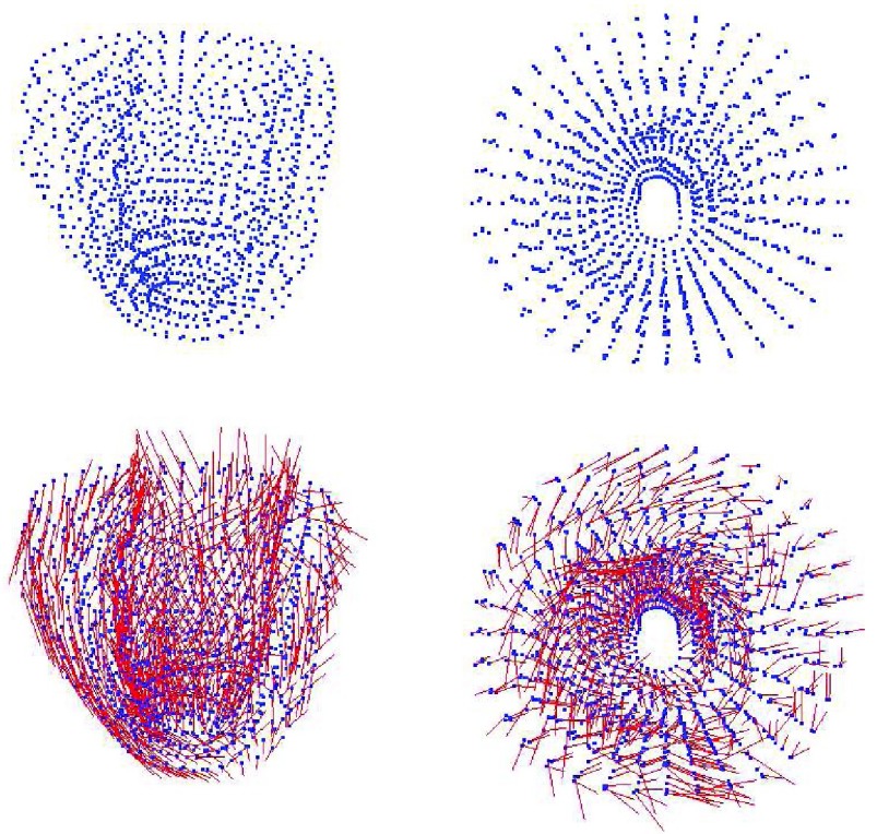
Many studies have provded that 70% of myocardium consist of myocytes, which are connected together by collagen to form muscle [46], [47]. These studies also show that the physical properties along and cross the myocardial fiber are different [48]. By taking advantaging of EFGM, we can efficiently construct the representation of anisotropic myocardial fibers by defining different local fiber orientation in each sampling node according its location inside myocardium (See Fig. 1 for examples).
FIGURE 1.
Top row: meshfree representations of the left ventricle (front view and top view), Bottom row: the fiber model of the left ventricle (front view and top view).
Influence domain: In the implementation of EFGM, every node will come with a domain of influence. Similar to FEM, neighboring nodes in that area can be used to approximate the current nodal values through shape function. That area is usually called the influence domain, with typically circular or rectangular shapes in 2D.
2). Construction of EFGM Shape Function
Just like the shape function in FEMs, the shape function of EFGM is used to generate approximation of the field variables using the values at sampling nodes inside the local influence domain. In FEMs, the shape functions are constructed using the mesh of elements. But in EFGM, the shape functions need to be constructed from sampling nodes without any predefined nodal connectivity. Furthermore, the following criteria should be obeyed during the construction of EFGM shape function: 1) Kronecker delta function: for easier imposing of essential boundary conditions; 2) compatibility: the approximated solution field is smooth and continuous in the entire problem domain; and 3) consistency: the ability of the approximated solution field to exactly represent the polynomial with desired order [39]. In EFGM, the moving least squares (MLS) approximation is applied to construct the shape function because it can be implemented easily with proper compatibility and consistency properties [49], [50].
a: MLS approximation
MLS approximation is mathematical method that can turn finite series representation of field variable into a local regression problem. The details of MLS approximation has been extensively explained in [7], [39], and [44]. One attractive feature of EFGM is that its shape function is continuous with first  derivatives if weight functions
  is continuous with first
  derivatives [49]. Furthermore, the numerical scheme for shape and its derivatives construction can be accelerated using more efficient [51].
b: Choice of basis and weight functions
The main purpose of basis functions is to enforce the consistency and accuracy of numerical results using special terms such as singularity functions. The basis functions in EFGM is always monomials of the lowest orders for minimum completeness [7], [39], [44]. In order to generate solution with special features, such as singularity, a singular enhancement function can be added into the basis function for the MLS approximation [49]. The weight functions is another important part to generate EFGM shape functions. Here are the properties of weight functions used in EFGM: The weight functions should be positive for a unique solution. In order to maintain a proper local neighbor influence, the magnitude of weight functions should be decreased when the distance increases. In order to satisfy the compatibility condition of the Hamilton’s principle, nodes should leave or enter the local influence domains defined by the weight functions in a smooth manner. In our implementation, the size of influence domain can be settle down after enough neighbor nodes are found to calculate the shape function. This notion is similar to the scale-space concept in vision. Moreover, it can facilitate the node distribution adaptively as well. The cubic spline function is used in the following cardiac image analysis works. In the demonstration of two-dimensional cardiac image analysis, we use tensor product concepts to establish the influence domains and calculate the weighting functions [52], [53].
The EFGM shape functions do not satisfy the Kronecker delta criterion, which results in that it actually approximates, rather than interpolate, the field variables. The approximation of field variables is determined by the parameters of all the nodes within the influence domain of node. Therefore, it is more difficult to enforce essential boundary conditions in EFGM than FEMs. Different techniques, such as penalty method or modified interpolating MLS approximations have been developed in order to remove this difficulty [54].
c). Modelling material discontinuities
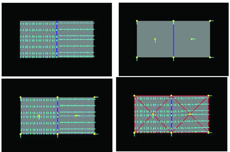
Fig. 2 shows that even only a few nodes are used, meshfree gives very good fiber fitting results, while FEM gives a much poor result for the same number of nodes. Meshfree result was obtained with linear basis functions using the same mesh points as FEM and the circular influence domain for each node. Given a point  and a real number
  , an influence domain was defined based on an ordering of all points according to Euclidean distance to the point
  , in which we were given a point
  and must return some point
  such that
  , if such a point existed. In FEM, linear triangular elements were used. This result is illustrated in Fig. 2 (bottom left) that the approximated fiber orientations are almost the same as the ground truth in Fig. 2 (top left), while in Fig. 2 (bottom right) the fiber orientations in the elements which comprised by nodes with different material properties deviate a lot form the ground truth. In FEM, a point inside one element need to use all the nodes of this for interpolation, even if the material properties are different inside this element. In the case of meshfree representation, since the points are not bounded by meshes and the influence domain size is adaptively determined, they can choose only the nodes with the same properties for approximation, as long as they get enough nodes so that the
  matrix is invertible.
FIGURE 2.
Comparison of fiber fitting results between FEM and EFGM. Top left: A composite object formed by two materials with different fibreous components, with the blue line indicating the interface (the ground truth). Top right: The 8 nodes (yellow) with fiber orientations (cyan) used for FEM interpolation or EFGM approximation. Bottom left: Fiber fitting result of EFGM, using the 8 nodes (yellow) meshfree representation. Bottom right: Fiber fitting result of FEM, using the 8 nodes (yellow) mesh (red).
Remeshing is a spatial subsampling strategy in FEM for achieving better approximation of field variables, i.e., because the order of polynomial interpolation function is determined by the elements used in the FEM mesh, more elements in the refined mesh can produce better discretization accuracy. However, the degrees of complication and implementation difficulty might greatly increase after the number of elements increased sharply with remesh. As a result, the efficiency and accuracy of FEM are largely determined by the remeshing method. Furthermore, because of complexity and large deformation of cardiac geometry, meshing or remshing method cannot be an automatic procedure, which means that it is a time consuming and labor-intensive procedure.
B. Meshfree Formulation
In this section, a meshfree computation strategy for cardiac image segmentation and cardiac motion analysis. A proper mathematical model of deformation and correlative solution algorithm are derived by using a defined shape function approximation about the deformation as mentioned above part. They together allow computationally efficiently handle large deformation and discontinuities with ease.
1). Meshfree Representation of Deformation Field
As discussed above, the cardiac geometry is first discretized by using a number of nodes whose displacements will completely define the shape’s deformation. After determining  nodes
nodes  inside the influence domain of interested location,
  shape functions, the deformation
  , and the deformed cardiac geometry can be defined using Eq. (1):
 |
Because EFGM uses a MLS shape functions constructed from the nodes inside the influence domain only, meshfree method for cardiac image analysis should find enough nodal displacement vectors  to approximate continuous field
  . In the following we will define these goal properties and show how
  can be solved using an energy minimization procedure. Because the EFGM shape funcition’s continuity is determined by the continuity of the weighting functions used in the MLS approximation, our meshfree method can have higher-order continuous approximation using a lower order polynomial basis
  for cardiac image analysis. Thus, after applying our meshfree method for cardiac motion analysis, we can directly calculate stress and strain fields without post-process like FEMs.
2). Construction of Weak Form in Meshfree
In order to obtain numerical solution, a Galerkin weak form of our meshfree method needs to be built over analysis domain in an integral sense [55]. For an elastic body of a given shape, its potential energy is defined as the energy of the deformation of the body (the strain energy) minus the work done on the body by the external forces.
Since a linear elastic material property under the Hamilton?s principle of work is used here [55], we can use material constitutive equation  to describe the relation between stress tensor
  and strain tensor
  with a material matrix
  . The strain tensor is either infinitesimal or finite type in this work. Therefore, strain tensor
  can be calculated from the displacement
  through equation
  where
where  is a differential operator matrix dependent on the strain types. Moreover, the strain energy
  can calculated from the strain and stress tensors in a linear elastic material property:
 |
where  is the problem domain. The work done by the external forces, including the body forces
  , the surface traction
  and the concentrated forces
 |
Therefore, we have equilibrium through variational derivative [7], [39], [44]
 |
In this application of left ventricle, the body forces  consist of gravity, surface traction
  and concentrated forces
  include pressures caused by intra-ventricular blood flow and the reaction forces caused by neighboring organs such as the lung.
Additionally, the inertia and damping forces are also considered as another part of the body forces, we obtain
 |
Here,  no longer includes inertia and damping forces,
  is mass density of the myocardium, and
  is the damping ratio.
3). Enforcement of Essential Boundary Conditions
Because the shape function of EFGM is contrasted from MLS approximation, it has no Kronecker delta function property like the FEM shape functions. Therefore, essential boundary conditions of displacement or kinematics can?t be directly enforced into problem domain. Thus, we add a penalty function into the Galerkin weak form formulation of Equation 6 to enforce essential boundary conditions.
We transform the enforcement of essential boundary condition into an optimization problem by minimizing the cost function  with respect to unknown variable
  with essential boundary conditions
  in problem domain
  . Therefore, a penalty function
  is added into
  :
:
 |
Then the modified Galerkin weak form can be obtained as:
 |
We use Dirichlet boundary condition as one example to enforce essential boundary condition here: if displacement  is prescribed on the boundary
  , we will add
  into Equation 8 as a penalty function. The value of penalty factor
  should be probably adjusted in different applications. Too small or too large values of penalty factor
  will result in an improper boundary condition or numerical instability. We have used the general rule of taking
  to be of order of
  as suggested in [56], with consistency of order
  and characteristic distance
  between nodal points in a meshfree method (The EFGM method is with bilinear consistency and
  ). We will demonstrate the performance of imposing boundary conditions using this penalty method with a FEM approach in the following experimental section.
4). Assemble of Governing System Equations
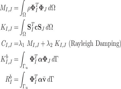
a: System equations
Taking Equation 2 into Equation 8, we can obtain a governing system equations under the principles of minimum work [55]:
 |
where  ,
,  , and
, and  are the mass matrix, the damping matrix, and the stiffness matrix respectively;
  is the displacement vector with
  nodes;
  is the external force including
  ,
,  and
and  ;
;  is the boundary condition penalty matrix;
  is the boundary condition force. All these vectors and matrices can be defined as:
 |
with in 2D
 |
where  and
and  are the derivatives of the EFGM shape functions with respect to
  and
and  respectively. In 3D case, with
 |
where  ,
, , and
, and  are the derivatives of EFGM shape function with respect to
  ,
,  , and
, and  respectively.
b: Integrals on background cells
In order to assemble the system matrices, we need to integrate the Galerkin weak form over the problem domain. This process can be achieved using a number of numerical techniques including Gauss quadrature [55]. In EFGM, the Gauss quadrature of Galerkin weak form is applied using a mesh of non-overlapping cells, called the background mesh. Obviously, the background mesh is not used for interpolation or approximation of field variable like EFGM shape function [44]. The popular background mesh of EFGM is regular-grid cell structure. However, there will be such a cell that only a portion belongs to the problem domain. We use a visibility scheme to separate the portion of cell that lies outside the problem domain. The density of regular-grid cell, i.e.  cells, is determined by the total number of nodes (
 ) inside the problem domain using the following principle
  [44]. Since we use Gauss quadrature over the background mesh, the number of quadrature points is also determined by the number of nodes inside each cell, i.e.
  quadrature points are used in two-dimensional cell where
  and
and  is the number of nodes in a cell. In three-dimensional cell, we use
  cells, where
  as defined above. In each cell, we use
  quadrature points.
III. Experiments and Results
In this section, we will apply EFGM framework to cardiac image segmentation and non-rigid cardiac motion analysis.
A. Handling Large Deformation in Segmentation
We solve the cardiac segmentation problem using an active deformable model with the bio-mechanical constraint. In this bio-mechanical constraint, an external image force defined by the EFGM-derived PDEs is used to evolve the boundary like classical Snakes model [57].
For annulus-shape object (such as shown in Fig. 3), we integrate an elastic solid mechanical model as a bio-mechanical constraint for imaging segmentation. In a meshfree formulation, the object is defined by the two boundaries and scattered particles in-between, so that the snake is divided into “snaxels”. Field variables in each point can be represented smoothly using EFGM shape function  and neighboring nodal variables
  . Then, the field variables of all the points are assembled respectively into the snake nodal variable vector
  , and thus Equation (9) can be defined as:
 |
where external image force can be defined as  , and
, and  is the image force.
FIGURE 3.
FEM (left) and EFGM (right) solutions of the annulus-shaped elastic solid model segmentation for synthetic image: initialization (top) and final results (bottom).
We consider the external image force as one kind of image gradient vector flow (GVF). We compare the performance of standard linear FEM and meshfree method to solve equilibrium state using similar strategy in [13] in the following experiments. We integrate equation (20) using an explicit Euler procedure with time step  . Specifically, this evolution process can be defined as:
 |
and therefore,
 |
where  and
and  are the displacement at step
  and
and  respectively,
  is an identity matrix, and
  is the force vector at step
  . The evolution will stop if the external force
  becomes smaller and/or when the displacement difference between iterations
  is below certain threshold. In our implementation, step
  and
and  are used to indicate two successive cardiac frames in the sequence.
1). Experiments on Synthetic Data
Large deformation issues is always encountered in cardiac segmentation because of cardiac contraction. Fig. 3 shows the results of annulus-shaped elastic solid model-constrained segmentation using linear standard FEM (without adaptive remeshing) and EFGM on synthetic image. Because the elemental shape function is used to build interpolation of filed variables of nodes, it is necessary to construct an approximation of field variable within the element using all the nodes of this element. On the contrary, because there is no explicit elemental connectivity in EFGM method, the relations between nodes are approximated by the field variable of nodes inside influence domains. The number of Gauss points and sizes of influence domains can be adjusted to achieve the desired accuracy. As the demonstration, linear FEM method without adaptive remeshing is unable to handle large geometrical changes, while meshfree framework ensure the snake moves much more smoothly over the image to capture the object boundary efficiently.
In the next experiment, we apply both FEM and meshfree framework to detect and track 3D myocardial boundary from a synthetic data set. The canine heart model provided by University of Auckland with both the in vitro geometry and fibrous-sheet architecture of 79,860 points, was adopted to generate the synthetic data [47]. A representation of this heart model over 1746 nodes was built from this canine heart model with neglecting apex elements, as shown in Fig. 4. The Young’s moduli was set to be 75kPa. The Poisson’s ratio had been set to be 0.47 to simulate incompressibility. We use this heart model as geometrical definition, and simulate the heart motion as the ground truth using one physiome platform from [58]. 50 frames of the whole cardiac cycle in 450 ms were obtained, and these motion data were then converted into a gray scale as an image sequence of 50 frames with image size  , space resolution
  . We also added 5dB SNR noises into these generated synthetic images.
FIGURE 4.
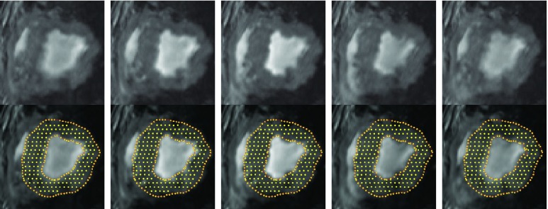
Top row: MR images at frames #1, #4, #7, #10 and #13; Bottom row: corresponding segmentation results.
The original canine heart model was used to track the boundary of the heart through the synthetic image sequence for both FEM (linear tetrahedra elements, without refinement) and meshfree framework (linear bases, without refinement). Fig. 3 shows the results under FEM framework and provides the meshfree solution results with quantitative evaluation of average positional errors compiled across all time frames for the complete 3D geometry. The positional error is defined as the distance between the estimated boundary point and ground truth. The positional error of each data is shown by the mean ± standard deviation. Overall, results obtained with meshfree representation tends to stick to true object boundary. It has been proved that the segmented shape of the whole heart with meshfree representation is more close to the boundary defined in the image. It is concluded refinement is necessary for the FEMs to handle large geometrical changes even with accurate snake initialization. Furthermore, meshfree representation even without refinement can tolerate more large geometrical changes.
2). Experiments on MRI Data
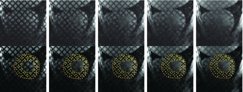
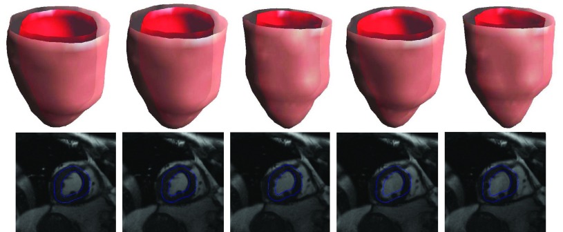
As shown in Fig. 4, the proposed meshfree framework is capable of segmenting the myocardial boundaries in an MRI image sequence. In Fig. 5, we show the results of segmentation of left ventricle from a tagging MRI image sequence. Note that, because of blurred tagging lines and inhomogeneity of intensity, meshfree method encounters difficulties to give better results. This problem can be overcome by using more complicated external forces. To test the ability of the new representation and computation strategy in segmenting 3D object, we also use the proposed method to the segmentation of left ventricle on a human MRI image data. The results in Fig. 6 look promising. However, the FEM using linear basis fails to process these kinds of data because the distortion of mesh caused by large deformation
FIGURE 5.
Top row: Tagging images at frames #1, #4, #7, #10, and #13; Bottom row: segmentation results at frames #1, #4, #7, #10, and #13;.
FIGURE 6.
Experimental results at frames #3, #6, #9, #12, and #16 using meshfree framework. Top: selected volume segmentation results. Bottom: segmentation results (blue contours) overlaid on the original image.
B. Handling Discontinuities in Cardiac Motion Analysis
Cardiac motion analysis is still one hot topic in our researching community. Please note there is a discontinuity in fiber angle because of the merging of right ventricular wall and left ventricular wall in septum. Moreover, myocardial fibers are placed in connected layers or sheets and there is substantial discontinuity between each layer. How to handle this discontinuity usually associated with large deformation for the heart in computation environment is an important issue, because this affects the numerical accuracy, computational feasibility and implementation difficulty. In order to overcome these difficulties, we use meshfree method to extract left ventricular motion with a bio-mechanical constraint through a state-space scheme that can generate optimal multi-frame estimation using Kalman filter [7].
If a linear time-invariant stochastic system is assumed [7], the system dynamics described by Equation 9 can converted into a discrete-time state-space representation. Then, we can define the system dynamics and measurement  using the following discrete-time equations:
 |
where  and
and  , with
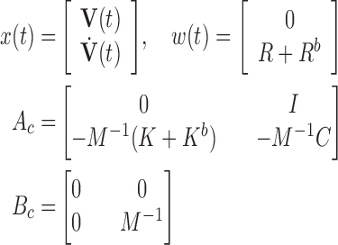 |
Where  is the measurement matrix,
  is the white process (
 ,
,  ),
),  is the white measurement noise (
 ,
,  ), and
  is the constant time interval. A Kalman filtering processing is then executed to generate optimal estimation [7].
In general, the myocardium has complicated, anisotropic mechanical properties in terms of its realistic constitutive laws ([2]). For computational feasibility, we adopt the linear elastic model in this paper to illustrate the potentials of our framework. For such material, the stress ( ) and strain (
 ) relationship (the constitutive law) obeys Hooker’s law, which states that the stress tensor is linearly proportional to the stain tensor:
 |
where the material matrix  composes a fourth-rank tensor and reduce to
  matrix for an anisotropic material.
Because of varying fiber orientations inside myocardium, the anisotropic biomechanical model should be used to describe the intrinsic behavior of the myocardium. Thus, the relation of stress and strain at different locations can be different under the same coordinates system, and  is changing at different location. Fig. 1 shows the fiber structure of the canine data.
Let us define  as the material matrix with
  (along
  -axis) fiber orientation:
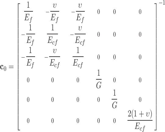 |
Here,  and
and  are the along fiber and across fiber Young’s modulus respectively.
  is Poisson’s ratio, which is a measure of incompressibility.
  describes the shearing property.
The stress-strain relationship in Equation (27) is defined in a material coordinate with respect to local fiber direction because the fiber direction changes largely from epicardium and endocardium [47]. In order to assemble the system matrix, we will transform stress-strain tensors from a material coordinate to a global coordinate in EFGM. Assuming the local coordinate system has  degrees horizontal angle and
  degrees vertical angle apart from the global coordinate system, then the corresponding stiffness matrix in the global coordinate can be given as:
 |
 is a combination transformation matrix of
  and
and  :
:
 |
with:
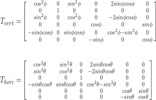 |
 is a matrix responsible for the transformation between strain and engineering strain:
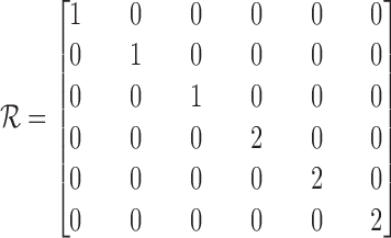 |
1). Experiments on Synthetic Data
A 2D deformable object formed by two pieces of materials with the same fibrous material property ( ) but different fiber orientations has been used.
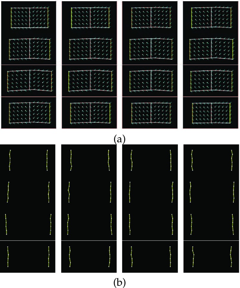
The fiber orientations of the left part are −45°, while the right part are 45°. We set the Young’s moduli along the fiber to 75kPa and cross the fiber to 25kPa separately. The Poisson’s ratio has been set to be 0.47. The object has 66 nodes in total and forces are applied outwards and horizontally to the six nodes on the left edge and the six nodes on the right edge to make it deform cyclically, and there have been sixteen frames capturing one whole cycle of the deformation (Fig. 7(a)). The resulting displacements on the left and right edges have been set to be the boundary displacements as input, and noises (SNR = 2.912dB) have been added on them to simulate the measurement errors (Fig. 7(b)). The displacement fields were recovered by the Kalman filter approach with meshfree and FEM representation.
FIGURE 7.
(a). The sixteen frames of the motion cycle of the ground truth (left to right, up to down). The yellow lines indicate the locations of applying forces, and the cyan lines indicate the fiber orientations. (b). The noise added boundaries of the sixteen frames serve as the noisy observations (SNR = 2.912dB).
In the first experiment, we compare the penalty method for the imposing of boundary conditions in EFGM method with the linear triangular standard finite element approach, where both of them employ the isotropic material model constraints. In this example, the distance between nodal points is  , thus the penalty parameter
  can be determined. Table 1 summarizes the means and standard deviations of the nodal position differences between the results of the two algorithms and the ground truth. Under the same boundary displacements and the same isotropic material model, very similar results are obtained.
TABLE 1. Comparison of Results Obtained With the Penalty Method for the Imposing of Boundary Conditions in EFGM Method and a FEM Approach. Each Data Cell Represents Mean and Standard Deviation of the Position Differences Between the Ground Truth and Corresponding Algorithms. The Total Mean and Standard Deviation for Each Algorithm are Calculated Using all the Nodal Differences of the Sixteen Frames. EFGM: Total Mean: 0.2298, Total s.d.: 0.1878. FEM: Total Mean: 0.2279, Total s.d.: 0.1936.
| EFGM(frame#1 – 4) | 0.0225 ± 0.0628 | 0.1547 ± 0.0797 | 0.1867 ± 0.0610 | 0.1702 ± 0.1021 |
| EFGM(frame#5 – 8) | 0.2991 ± 0.1769 | 0.2943 ± 0.1771 | 0.3214 ± 0.2011 | 0.3314 ± 0.2467 |
| EFGM(frame#9 – 12) | 0.3310 ± 0.2701 | 0.4111 ± 0.2812 | 0.3112 ± 0.1978 | 0.3324 ± 0.1950 |
| EFGM(frame#13 – 16) | 0.2117 ± 0.1396 | 0.1502 ± 0.0871 | 0.1511 ± 0.0748 | 0.1276 ± 0.0590 |
| FEM(frame#1 – 4) | 0.0245 ± 0.0328 | 0.1267 ± 0.0482 | 0.1611 ± 0.1123 | 0.2110 ± 0.1423 |
| FEM(frame#5 – 8) | 0.2396 ± 0.1819 | 0.2944 ± 0.2211 | 0.3199 ± 0.2507 | 0.3581 ± 0.3001 |
| FEM(frame#9 – 12) | 0.3994 ± 0.3111 | 0.3641 ± 0.2691 | 0.3102 ± 0.2275 | 0.2887 ± 0.2108 |
| FEM(frame#13 – 16) | 0.2488 ± 0.1689 | 0.1994 ± 0.1176 | 0.1473± 0.0698 | 0.0990 ± 0.0392 |
In the second experiment, the same condition as described above has been used, except that an anisotropic material model taking into account fiber orientations is employed. From Table 2, it can be seen that the displacement fields estimated using meshfree representation are better. This is mainly because the meshfree representation can naturally handle fiber discontinuous and has the nature to avoid the problem caused by element skewing.
TABLE 2. Comparison of Results Between EFGM (Linear Bases) and Linear Triangular Finite Element Approach. Each Data Cell Represents Mean and Standard Deviation of the Position Differences Between the Ground Truth and Corresponding Algorithms. The Total Mean and Standard Deviation for Each Algorithm are Calculated Using All the Nodal Differences of the Sixteen Frames. EFGM: Total Mean: 0.1189, Total s.d.: 0.0672. FEM: Total Mean: 0.1793, Total s.d.: 0.1166.
| EFGM(frame#1 – 4) | 0.0987 ± 0.0565 | 0.1097 ± 0.0589 | 0.0971 ± 0.0591 | 0.1291 ± 0.0478 |
| EFGM(frame#5 – 8) | 0.0704 ± 0.0696 | 0.1478 ± 0.0599 | 0.1201 ± 0.0500 | 0.0689 ± 0.0212 |
| EFGM(frame#9 – 12) | 0.1097 ± 0.0705 | 0.1511 ± 0.0562 | 0.0679 ± 0.0502 | 0.1616 ± 0.0571 |
| EFGM(frame#13 – 16) | 0.1198 ± 0.0501 | 0.1493 ± 0.0671 | 0.1267 ± 0.0605 | 0.1109 ± 0.0876 |
| FEM(frame#1 – 4) | 0.0218 ± 0.0598 | 0.1043 ± 0.0611 | 0.1074 ± 0.0634 | 0.1308 ± 0.0581 |
| FEM(frame#5 – 8) | 0.1032 ± 0.0701 | 0.1871 ± 0.0901 | 0.2299 ± 0.0898 | 0.2693 ± 0.1096 |
| FEM(frame#9 – 12) | 0.3987 ± 0.1075 | 0.2016 ± 0.0918 | 0.2749 ± 0.0960 | 0.1712 ± 0.0801 |
| FEM(frame#13 – 16) | 0.1506 ± 0.1018 | 0.2018 ± 0.1231 | 0.1305 ± 0.0923 | 0.1105 ± 0.0992 |
2). Experiments on MRI Data
We have implemented the algorithm on normal canine cardiac MRI data set. The in-plane image resolution is 1.64 mm/pixel. The inter-plane image resolution is 5 mm/pixel. The temporal resolution is 40 msec/frame. 2D contours of the first frame’s image data are extracted using level set method. Then a set of sample points are allocated in the myocardium domain bounded by endo- and epicardial boundaries. We register the fiber orientations from the Cardiac Mechanics Research Group at UCSD1 into our cardiac MRI data using the principle warps, as shown in Fig. 1. Because we treat the myocardium as an anisotropic linear elastic material, ee set the Young’s moduli along the fiber to 75kPa and cross the fiber to 25kPa separately. The Poisson’s ratio has been set to be 0.47 [59], [60]. Following the procedures established in [61], endocardial and epicardial boundaries, and the boundary point displacements between consecutive frames are extracted. Then, given these partial, image-derived measurements on the cardiac kinematics, the meshfree estimation framework described above and the traditional standard FEM method are employed to recover the dense displacement field over the entire cardiac cycle. Details on these procedures can be found in our papers [7], [30].
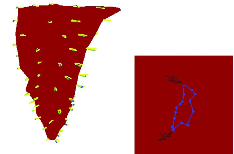
The EFGM estimated complete trajectories of subsampled points over the cardiac cycle (16 temporal frames) superimposed onto the rendered endocardial surfaces at end of systole (ES) are shown in Fig. 8. Evidently, the trajectories of all the points are almost a complete loop, meaning the points move back to where they begin. Also these points move outside during the contraction phase (end of diastole (ED) to ES) and they move inside during the expansion phase (ES to ED).
FIGURE 8.
Left: complete trajectories of selected points over the cardiac cycle (sixteen temporal frames) shown against the endocardial surface at ES obtained by EFGM method. Right: closeup which illustrates a trajectory of one point.
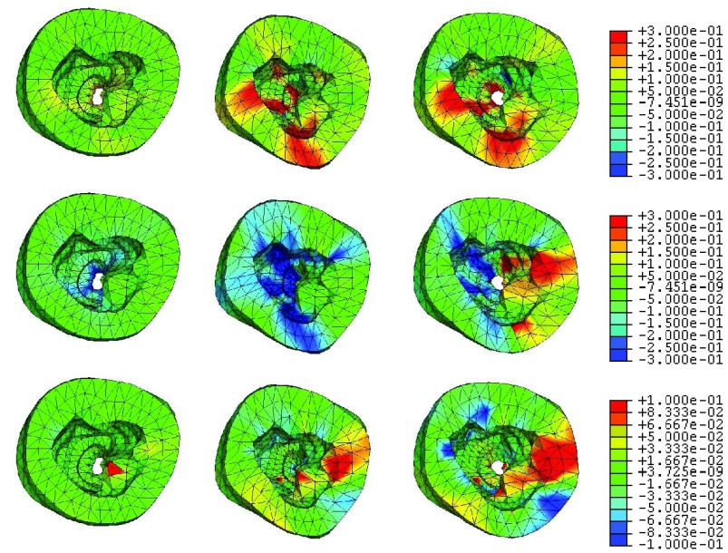
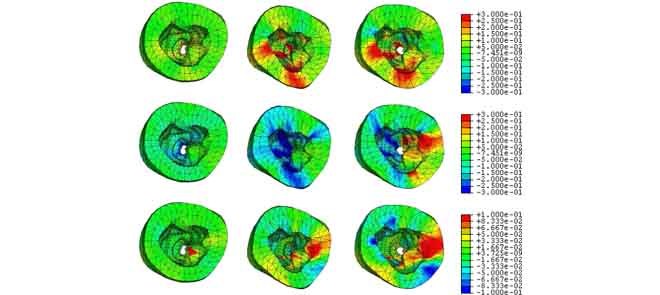
The top view of the strain maps of certain frames are shown in Fig. 9 (EFGM method) and Fig. 10 (FEM method). For the EFGM results, we find that the average value of the radial strain is large at ES, the longitudinal strain is small, and the circumferential strain reaches minimum at ES. Comparing with linear FEM results, the strains obtained by EFGM method are much consistent over the cardiac cycle.
FIGURE 9.
EFGM framework estimated strain maps overlaid the corresponding deformed heart with respect to end-diastole (canine MR images, frames #3, #9, #14 (left to right)): radial strains (top), circumferential strains (middle), and longitudinal strains (bottom).
FIGURE 10.
FEM method estimated strain maps overlaid the corresponding deformed heart with respect to end-diastole (canine MR images, frames #3, #9, #14 (left to right)): radial strains (top), circumferential strains (middle), and longitudinal strains (bottom).
Because of linear interpolation used in linear FEM element, the displacement field and fiber orientation can only be described by a linear shape function. However, our EFGM framework has a good  -adaptivity, where
  and
and  are the sizes of influence domains and the order of polynomial respectively. The
  -adaptivity of EFGM can ensure a higher order continuity using polynomial bases
  with more nodes. In our FEGM framework, more nodes can be conveniently acquired by simply increase the size of the influence domains. In the contrary, FEMs need to change the element type to introduce higher order polynomial. Moreover, element with higher order polynomial bases will increase the complexity of mesh, which lead to more labor-intensive meshing procedure. Therefore, the EFGM framework can efficiently process cardiac image because of meshfree methods’ flexible node distribution. Furthermore, our EFGM framework can better approximate myocardial fiber orientation using a cubic spline weight function with fewer nodes.
Additionally, different patients’ data require different meshes, and even for the same patient, different mesh might be required for different image modalities. Therefore, we do not recommend FEM to process a large volume of cardiac image analysis because of great meshing difficulty. In this sense, meshfree representation presents an effective, simple way to represent the complicated architecture of the heart.
IV. Conclusion and Perspectives
In this paper, we use a meshfree particle computational method for cardiac image analysis with the energy minimization formulations in the Lagrangian sense to solve the fundamental problem about the optimal mathematical description in cardiac image analysis on a digital computer. This meshfree method only uses the nodal points to discretize problem domain without any pre-defined meshing structure. In our experiments, the performance of this meshfree is verified in cardiac image segmentation and cardiac motion analysis. Since meshfree representation have minimal consistency constraints, handling large deformation and material discontinuities are simple and efficient.
It should be noted that the computationally complexity of meshfree is higher than FEM for the same number of nodes. However, as above demonstration the meshfree method with linear base provides more accurate results than linear standard FEM when using the same number of nodes. In other words, the meshfree method with fewer nodes can achieve the same accuracy as the FEM with more nodes. In a conclusion, the efficiency of meshfree method is better than FEM using the same numerical accuracy requirement. As a result, meshfree methods provide a way to avoid the complicated meshing procedures while preserving the accuracy with a relatively small number of nodes.
However, there are notable efforts aimed at developing fast, automatic meshing algorithms for high order elements [62]. With the further development of the meshing strategy, the other interesting directions for future research are improving the implementation efficiency of meshfree methods.
Funding Statement
This work was supported in part by the National Key Technology Research and Development Program of China under Grant 2016YFC1300302, Grant 2017YFE0104000, and Grant 2016YFC1301700, the National Natural Science Foundation of China under Grant 61525106, Grant 61427807, Grant 61701436, and Grant 61771464, the Shenzhen Innovation Funding under Grant JCYJ20170413114916687 and Grant JCYJ20170306090501763, the Science and the Technology Planning Project of Guangdong Province under Grant 2014A020212257 and Grant 2013A022100036, the Guangzhou Science and Technology Planning Project under Grant 201704020079, and the Project funded by China Postdoctoral Science Foundation under Grant 2017M620394.
Footnotes
References
- [1].Pourmorteza A., Schuleri K. H., Herzka D. A., Lardo A. C., and McVeigh E. R., “Regional cardiac function assessment in 4D CT: Co mparison between SQUEEZ and ejection fraction,” in Proc. Annu. Int. Conf. IEEE Eng. Med. Biol. Soc. (EMBC), Aug./Sep. 2012, pp. 4966–4969. [DOI] [PubMed] [Google Scholar]
- [2].Glass L., Hunter P., and McCulloch A., Theory Heart. Berlin, Germany: Springer-Verlag, 1991. [Google Scholar]
- [3].Frangi A. F., Niessen W. J., and Viergever M. A., “Three-dimensional modeling for functional analysis of cardiac images: A review,” IEEE Trans. Med. Imag., vol. 20, no. 1, pp. 2–5, Jan. 2001. [DOI] [PubMed] [Google Scholar]
- [4].Wang H. and Amini A. A., “Cardiac motion and deformation recovery from MRI: A review,” IEEE Trans. Med. Imag., vol. 31, no. 2, pp. 487–503, Feb. 2012. [DOI] [PubMed] [Google Scholar]
- [5].Young A. A. and Prince J. L., “Cardiovascular magnetic resonance: Deeper insights through bioengineering,” Annu. Rev. Biomed. Eng., vol. 15, no. 5, pp. 433–461, 2013. [DOI] [PubMed] [Google Scholar]
- [6].Folgoc L. L., Delingette H., Criminisi A., and Ayache N., “Current-based 4D shape analysis for the mechanical personalization of heart models,” in Proc. Int. MICCAI Workshop Med. Comput. Vis. (MCV), 2012, pp. 283–292. [Google Scholar]
- [7].Liu H. and Shi P., “Meshfree representation and computation: Applications to cardiac motion analysis,” in Proc. Biennial Int. Conf. Inf. Process. Med. Imag. (IPMI), 2003, pp. 487–498. [DOI] [PubMed] [Google Scholar]
- [8].Wang X.et al. , “Meshless deformable models for 3D cardiac motion and strain analysis from tagged MRI,” Magn. Reson. Imag., vol. 33, no. 1, pp. 146–160, 2015. [DOI] [PMC free article] [PubMed] [Google Scholar]
- [9].Wang X., Chen T., Zhang S., Metaxas D., and Axel L., “LV motion and strain computation from tMRI based on meshless deformable models,” in Proc. Int. Conf. Med. Image Comput. Comput.-Assist. Intervent (MICCAI), 2008, pp. 636–644. [DOI] [PubMed] [Google Scholar]
- [10].Wang X., Metaxas D., Chen T., and Axel L., “Meshless deformable models for LV motion analysis,” in Proc. IEEE Conf. Comput. Vis. Pattern Recognit. (CVPR), Jun. 2008, pp. 1–8. [Google Scholar]
- [11].Wong K. C. L., Wang L., Zhang H., Liu H., and Shi P., “Meshfree implementation of individualized active cardiac dynamics,” Comput. Med. Imag. Graph., vol. 34, no. 1, pp. 91–103, 2010. [DOI] [PubMed] [Google Scholar]
- [12].Suinesiaputra A.et al. , “A collaborative resource to build consensus for automated left ventricular segmentation of cardiac MR images,” Med. Image Anal., vol. 18, no. 1, pp. 50–62, 2014. [DOI] [PMC free article] [PubMed] [Google Scholar]
- [13].Cohen L. D. and Cohen I., “Finite-element methods for active contour models and balloons for 2-D and 3-D images,” IEEE Trans. Pattern Anal. Mach. Intell., vol. 15, no. 11, pp. 1131–1147, Nov. 1993. [Google Scholar]
- [14].Young A. A., Kraitchman D. L., Dougherty L., and Axel L., “Tracking and finite element analysis of stripe deformation in magnetic resonance tagging,” IEEE Trans. Med. Imag., vol. 14, no. 3, pp. 413–421, Sep. 1995. [DOI] [PubMed] [Google Scholar]
- [15].Montagnat J. and Delingette H., “4D deformable models with temporal constraints: Application to 4D cardiac image segmentation,” Med. Image Anal., vol. 9, no. 1, pp. 87–100, Feb. 2005. [DOI] [PubMed] [Google Scholar]
- [16].Sermesant M., Delingette H., and Ayache N., “An electromechanical model of the heart for image analysis and simulation,” IEEE Trans. Med. Imag., vol. 25, no. 5, pp. 612–625, May 2006. [DOI] [PubMed] [Google Scholar]
- [17].Ecabert O.et al. , “Automatic model-based segmentation of the heart in CT images,” IEEE Trans. Med. Imag., vol. 27, no. 9, pp. 1189–1201, Sep. 2008. [DOI] [PubMed] [Google Scholar]
- [18].Zhu Y., Papademetris X., Sinusas A. J., and Duncan J. S., “Segmentation of the left ventricle from cardiac MR images using a subject-specific dynamical model,” IEEE Trans. Med. Imag., vol. 29, no. 3, pp. 669–687, Mar. 2010. [DOI] [PMC free article] [PubMed] [Google Scholar]
- [19].Gopal S. and Terzopoulos D., “A unified statistical/deterministic deformable model for LV segmentation in cardiac MRI,” in Proc. Int. Workshop Statist. Atlases Comput. Models Heart (STACOM), 2013, pp. 180–187. [Google Scholar]
- [20].Wittek A.et al. , “In vivo determination of elastic properties of the human aorta based on 4D ultrasound data,” J. Mech. Behavior Biomed. Mater., vol. 27, no. 11, pp. 167–183, 2013. [DOI] [PubMed] [Google Scholar]
- [21].Karimi A., Navidbakhsh M., Faghihi S., Shojaei A., and Hassani K., “A finite element investigation on plaque vulnerability in realistic healthy and atherosclerotic human coronary arteries,” Proc. Inst. Mech. Eng., H, J. Eng. Med., vol. 227, no. 2, pp. 148–161, 2013. [DOI] [PubMed] [Google Scholar]
- [22].Jean A. and Engelmayr G. C. Jr., “Finite element analysis of an accordion-like honeycomb scaffold for cardiac tissue engineering,” J. Biomech., vol. 43, no. 15, pp. 3035–3043, 2010. [DOI] [PMC free article] [PubMed] [Google Scholar]
- [23].Augenstein K. F., Cowan B. R., LeGrice I. J., and Young A. A., “Estimation of cardiac hyperelastic material properties from MRI tissue tagging and diffusion tensor imaging,” in Proc. Int. Conf. Med. Image Comput. Comput.-Assist. Intervent (MICCAI), 2006, pp. 628–635. [DOI] [PubMed] [Google Scholar]
- [24].Wang V. Y., Lam H. I., Ennis D. B., Cowan B. R., Young A. A., and Nash M. P., “Modelling passive diastolic mechanics with quantitative MRI of cardiac structure and function,” Med. Image Anal., vol. 13, no. 5, pp. 773–784, 2009. [DOI] [PMC free article] [PubMed] [Google Scholar]
- [25].Sotiras A., Davatzikos C., and Paragios N., “Deformable medical image registration: A survey,” IEEE Trans. Med. Imag., vol. 32, no. 7, pp. 1153–1190, Jul. 2013. [DOI] [PMC free article] [PubMed] [Google Scholar]
- [26].Karatolios K., Wittek A., Blase C., Shelke A., Moosdorf R., and Vogt S., “Vascular modelling and wall motion analysis of ascending and descending aorta with 3D-ultrasound speckle tracking and finite element analysis,” Eur. Heart J., vol. 34, p. 247, Aug. 2013.23457726 [Google Scholar]
- [27].Tsap L. V., Goldof D. B., and Sarkar S., “Nonrigid motion analysis based on dynamic refinement of finite element models,” IEEE Trans. Pattern Anal. Mach. Intell., vol. 22, no. 5, pp. 526–543, May 2000. [Google Scholar]
- [28].Papademetris X., Sinusas A. J., Dione D. P., Constable R. T., and Duncan J. S., “Estimation of 3-D left ventricular deformation from medical images using biomechanical models,” IEEE Trans. Med. Imag., vol. 21, no. 7, pp. 786–800, Jul. 2002. [DOI] [PubMed] [Google Scholar]
- [29].Remme E. W., Augenstein K. F., Young A. A., and Hunter P. J., “Parameter distribution models for estimation of population based left ventricular deformation using sparse fiducial markers,” IEEE Trans. Med. Imag., vol. 24, no. 3, pp. 381–388, Mar. 2005. [DOI] [PubMed] [Google Scholar]
- [30].Liu H. and Shi P., “State-space analysis of cardiac motion with biomechanical constraints,” IEEE Trans. Image Process., vol. 16, no. 4, pp. 901–917, Apr. 2007. [DOI] [PubMed] [Google Scholar]
- [31].Yan P., Sinusas A., and Duncan J. S., “Boundary element method-based regularization for recovering of LV deformation,” Med. Image Anal., vol. 11, no. 6, pp. 540–554, 2007. [DOI] [PubMed] [Google Scholar]
- [32].Chen T., Wang X., Chung S., Metaxas D., and Axel L., “Automated 3D motion tracking using gabor filter bank, robust point matching, and deformable models,” IEEE Trans. Med. Imag., vol. 29, no. 1, pp. 1–11, Jan. 2010. [DOI] [PMC free article] [PubMed] [Google Scholar]
- [33].Delingette H.et al. , “Personalization of cardiac motion and contractility from images using variational data assimilation,” IEEE Trans. Biomed. Eng., vol. 59, no. 1, pp. 20–24, Jan. 2012. [DOI] [PubMed] [Google Scholar]
- [34].Tavakoli V. and Amini A. A., “A survey of shaped-based registration and segmentation techniques for cardiac images,” Comput. Vis. Image Understand., vol. 117, no. 9, pp. 966–989, 2013. [Google Scholar]
- [35].Ferrant M., Nabavi A., Macq B., Jolesz F. A., Kikinis R., and Warfield S. K., “Registration of 3-D intraoperative MR images of the brain using a finite-element biomechanical model,” IEEE Trans. Med. Imag., vol. 20, no. 12, pp. 1384–1397, Dec. 2001. [DOI] [PubMed] [Google Scholar]
- [36].Ledesma-Carbayo M. J.et al. , “Spatio-temporal nonrigid registration for ultrasound cardiac motion estimation,” IEEE Trans. Med. Imag., vol. 24, no. 9, pp. 1113–1126, Sep. 2005. [DOI] [PubMed] [Google Scholar]
- [37].Huang W.-C. and Goldgof D. B., “Adaptive-size meshes for rigid and nonrigid shape analysis and synthesis,” IEEE Trans. Pattern Anal. Mach. Intell., vol. 15, no. 6, pp. 611–616, Jun. 1993. [Google Scholar]
- [38].Liu G., Meshfree Methods: Moving Beyond the Finite Element Method. Berlin, Germany: Springer-Verlag, 2009. [Google Scholar]
- [39].Liu G., Mesh Free Methods. Boca Raton, FL, USA: CRC Press, 2003. [Google Scholar]
- [40].Belytschko T., Krongauz Y., Organ D., Fleming M., and Krysl P., “Meshless methods: An overview and recent developments,” Comput. Methods Appl. Mech. Eng., vol. 139, nos. 1–4, pp. 3–47, Dec. 1996. [Google Scholar]
- [41].Li S. and Liu W. K., “Meshfree and particle methods and their applications,” Appl. Mech. Rev., vol. 55, no. 1, pp. 1–34, 2002. [Google Scholar]
- [42].Li S. and Liu W. K., Meshfree Particle Methods. Berlin, Germany: Springer-Verlag, 2004. [Google Scholar]
- [43].Zhang L. T., Liu W. K., Li S. F., Qian D., and Hao S., “Survey of multi-scale meshfree particle methods,” in Meshfree Methods for Partial Differential Equations, Griebel M. and Schweitzer M. A., Eds. Berlin, Germany: Springer-Verlag, 2003, pp. 441–457. [Google Scholar]
- [44].Belytschko T., Lu Y. Y., and Gu L., “Element-free galerkin methods,” Int. J. Numer. Methods Eng., vol. 37, no. 2, pp. 229–256, 1994. [Google Scholar]
- [45].Fernández-Méndez S. and Huerta A., “Imposing essential boundary conditions in mesh-free methods,” Comput. Methods Appl. Mech. Eng., vol. 193, nos. 12–14, pp. 1257–1275, 2004. [Google Scholar]
- [46].Peeters T. H. J. M., Vilanova A., Strijkers G. J., and ter Haar Romeny B. M., “Visualization of the fibrous structure of the heart,” in Proc. Int. Fall Workshop Vis., Modeling Vis. (VMV), 2006, pp. 309–317. [Google Scholar]
- [47].Nielsen P. M., Le Grice I. J., Smaill B. H., and Hunter P. J., “Mathematical model of geometry and fibrous structure of the heart,” Comput. Methods Appl. Mech. Eng., vol. 260, no. 4, pp. H1365–H1378, 1991. [DOI] [PubMed] [Google Scholar]
- [48].Nash M. and Hunter P., “Computational mechanics of the heart: From tissue structure to ventricular function,” J. Elasticity Phys. Sci. Solids, vol. 61, nos. 1–3, pp. 113–141, 2000. [Google Scholar]
- [49].Lancaster P. and Salkauskas K., “Surfaces generated by moving least squares methods,” Math. Comput., vol. 37, no. 155, pp. 141–158, 1981. [Google Scholar]
- [50].Schaefer S., McPhail T., and Warren J., “Image deformation using moving least squares,” ACM Trans. Graph., vol. 25, no. 3, pp. 533–540, 2006. [Google Scholar]
- [51].Breitkopf P., Rassineux A., Touzot G., and Villon P., “Explicit form and efficient computation of MLS shape functions and their derivatives,” Int. J. Numer. Methods Eng., vol. 48, no. 3, pp. 451–466, 2000. [Google Scholar]
- [52].Zhang Z., Zhao P., and Liew K., “Improved element-free galerkin method for two-dimensional potential problems,” Eng. Anal. Boundary Elements, vol. 33, no. 4, pp. 547–554, 2009. [Google Scholar]
- [53].Dolbow J. and Belytschko T., “An introduction to programming the meshless element free Galerkin method,” Arch. Comput. Methods Eng., vol. 5, no. 3, pp. 207–241, 1998. [Google Scholar]
- [54].Kaljević I. and Saigal S., “An improved element free galerkin formulation,” Int. J. Numer. Methods Eng., vol. 40, no. 16, pp. 2953–2974, 1997. [Google Scholar]
- [55].Cook R. D., Malkus D. S., Plesha M. E., and Witt R. J., Concepts and Applications of Finite Element Analysis. Hoboken, NJ, USA: Wiley, 2002. [Google Scholar]
- [56].Arnold D. N., Brezzi F., Cockburn B., and Marini L. D., “Unified analysis of discontinuous Galerkin methods for elliptic problems,” SIAM J. Numer. Anal., vol. 39, no. 5, pp. 1749–1779, 2002. [Google Scholar]
- [57].Kass M., Witkin A., and Terzopoulos D., “Snakes: Active contour models,” Int. J. Comput. Vis., vol. 1, no. 4, pp. 321–331, 1988. [Google Scholar]
- [58].Wong K. C. L., Zhang H., Liu H., and Shi P., “Physiome-model–based state-space framework for cardiac deformation recovery,” Acad. Radiol., vol. 14, no. 11, pp. 1341–1349, 2007. [DOI] [PubMed] [Google Scholar]
- [59].Jawad H., Ali N. N., Lyon A. R., Chen Q. Z., Harding S. E., and Boccaccini A. R., “Myocardial tissue engineering: A review,” J. Tissue Eng. Regenerative Med., vol. 1, no. 5, pp. 327–342, 2007. [DOI] [PubMed] [Google Scholar]
- [60].Yamada H., Strength of Biological Material. Baltimore, MD, USA: Williams & Wilkins, 1970. [Google Scholar]
- [61].Shi P., Sinusas A. J., Constable R. T., Ritman E., and Duncan J. S., “Point-tracked quantitative analysis of left ventricular surface motion from 3-D image sequences,” IEEE Trans. Med. Imag., vol. 19, no. 1, pp. 36–50, Jan. 2000. [DOI] [PubMed] [Google Scholar]
- [62].Lamata P.et al. , “An accurate, fast and robust method to generate patient-specific cubic Hermite meshes,” Med. Image Anal., vol. 15, no. 6, pp. 801–813, 2011. [DOI] [PubMed] [Google Scholar]


