 The facile non-radiative decay for gold(iii) complexes is due to the thermally accessible 3LLCT, but not the usually assumed 3dd excited state.
Abstract
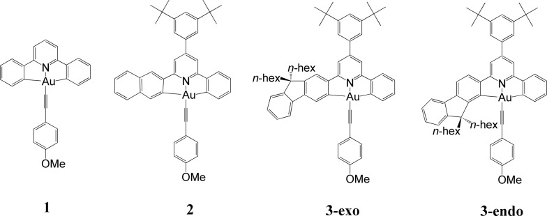
We have performed theoretical analyses of the photophysical properties of a series of cyclometalated gold(iii) arylacetylide complexes, [(C^N^C)AuIIIC CPh-4-OMe], with different extents of π-conjugation at the doubly C-deprotonated [C^N^C] ligand via replacement of one of the phenyl moieties in the non-conjugated CH^N^C ligand (1) by a naphthalenyl (2) or a fluorenyl moiety (3-exo and 3-endo; HCH^N^CH = 2,6-diphenylpyridine). Conforming to the conventional wisdom that extended π-conjugation imposes rigidity on the structure of the 3IL(ππ*(C^N^C)) excited state (IL = intraligand), the calculated Huang–Rhys factors for the 3IL → S0 transition follow the order: 1 > 2 > 3-exo ∼ 3-endo, which corroborates qualitatively the experimental non-radiative decay rate constants, knr: 1 ≫ 2 > 3-exo, but not 3-endo. Density Functional Theory (DFT) calculations revealed that there is an additional triplet excited state minimum of 3LLCT character (LLCT = ligand-to-ligand charge transfer; 3[π(C CPh-4-OMe) → π*(C^N^C)]) for complexes 1 and 3-endo. This 3LLCT excited state, possessing a large out-of-plane torsional motion between the planes of the C^N^C and arylacetylide ligands, has a double minimum anharmonic potential energy surface along this torsional coordinate which leads to enhanced Franck–Condon overlap between the 3LLCT excited state and the ground state. Together with the larger spin–orbit coupling (SOC) and solvent reorganization energy for the 3LLCT → S0 transition compared with those for the 3IL → S0 transition, the calculated knr values for the 3LLCT → S0 transition are more than 690- and 1500-fold greater than the corresponding 3IL → S0 transition for complexes 1 and 3-endo respectively. Importantly, when this 3LLCT → S0 decay channel is taken into consideration, the non-radiative decay rate constant knr could be reproduced quantitatively and in the order of: 1 ≫ 3-endo, 2 > 3-exo. This challenges the common view that the facile non-radiative decay rate of transition metal complexes is due to the presence of a low-lying metal-centred 3dd or 3LMCT excited state (LMCT = ligand-to-metal charge transfer). By analysis of the relative order of MOs of the chromophoric [C^N^C] cyclometalated and arylacetylide ligands, one may discern why complexes 1 and 3-endo have a low-lying 3LLCT excited state while 3-exo does not.
Introduction
Gold(iii) complexes are being actively studied as potential anticancer drugs1 and catalysts.2,3 However, the study of the spectroscopic and luminescent properties of gold(iii) complexes is still in its infancy, in particular when compared to their isoelectronic platinum(ii) counterparts, which are known to display rich photophysical behaviours. One of the impediments to the progress of photoluminescence of gold(iii) complexes is the high electrophilicity of the gold(iii) ion and the presence of a low-lying Au(5dσ*) orbital. In effect, the deactivating ligand-to-metal charge transfer (LMCT) and/or dd ligand-field excited states become close in energy to the emitting excited state, leading to efficient luminescence quenching in gold(iii) complexes.4 To circumvent this problem, Yam and co-workers have coupled various strong σ-donating ligands, such as arylacetylide and N-heterocyclic carbenes (NHC), to the gold(iii) cyclometalated complexes; these complexes were reported to be weakly emissive in solution (φ < 0.01) at room temperature.5
To enhance the emission quantum yield, the structural distortion between the emitting excited state and the ground state must be minimized, thereby decreasing the non-radiative decay rate.6 This can be achieved by designing emitting molecules with highly rigid ligand scaffolds, for example, by extended π-conjugation at the cyclometalated ligand7 (see Table 1 for a comparison between the emission quantum yields of selected examples of gold(iii) cyclometalated complexes with different extents of π-conjugation at the [C^N^C] ligand).3a,5,8 A particularly striking example is the series of gold(iii) complexes with a fluorenyl moiety incorporated into the doubly deprotonated [C^N^C] ligand.3a In this case, the room temperature emission quantum yields of the gold(iii) cyclometalated complexes in solution reach 0.58, and the corresponding non-radiative decay rate constant (knr) falls to 1.74 × 10³ s–1 (Table 1, column 5). In other words, knr drops more than four orders of magnitude when one of the phenyl moieties in the non-conjugated CH^N^C ligand (Table 1, column 2; HCH^N^CH = 2,6-diphenylpyridine) is replaced by a fluorenyl moiety.3a Similar enhancement in emission quantum yield has also been reported for fluorene-functionalized cyclometalated platinum(ii) complexes when compared with the non-conjugated CH^N^C analogue;9 the enhanced luminescence is attributed to the rigid π-conjugated fluorene unit which minimizes structural distortion between the emitting triplet excited state and the ground state.
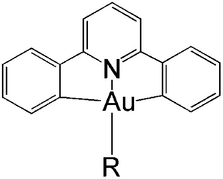
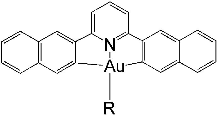
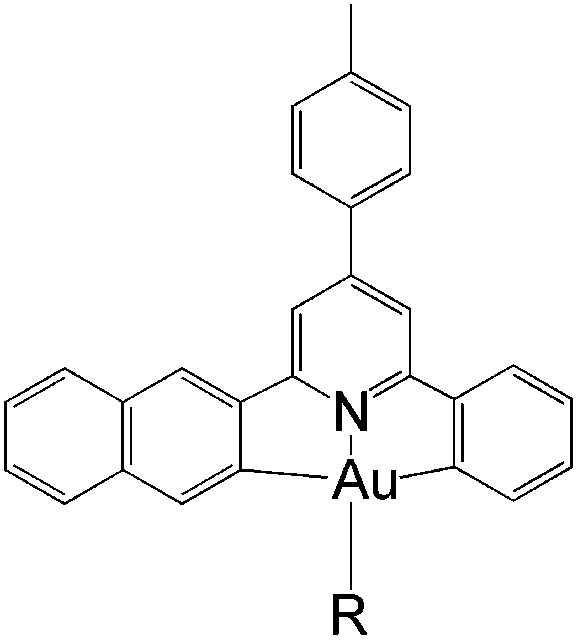
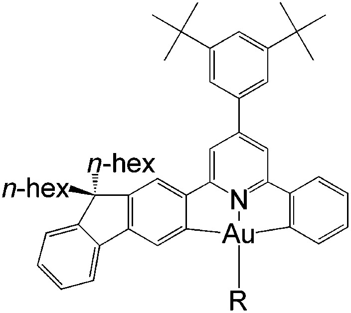
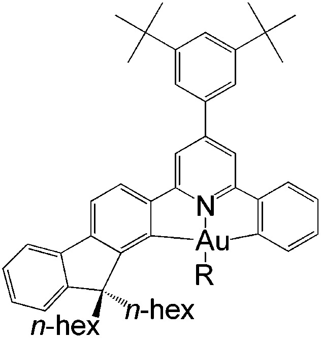
Table 1. Photophysical properties of gold(iii) pincer-type complexes in dichloromethane solution at room temperature. For R = C CPh-4-OMe, n = 0 and for R = 1,3-dimethylimidazol-2-ylidene, n = 1. CX^N^C = pincer-type cyclometalated ligand; X = H, np, or fl.
|
|
|
|
|
|
| [AuIII(CH^N^C)R]n | [AuIII(Cnp^N^Cnp)R]n | [AuIII(Cnp^N^C)R]n | exo-[AuIII(Cfl^N^C)R]n | endo-[AuIII(Cfl^N^C)R]n | |
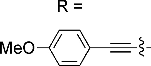
|
φ = 0.0004 | φ = 0.08 | φ = 0.09 | φ = 0.58 | φ = 0.02 |
| τ = 0.017 μs3a,5b | τ = 64 μs8a | τ = 25 μs8a | τ = 242 μs3a | τ = 14.5 μs (this work) | |
| k nr = 5.88 × 10⁷ s–1 | k nr = 1.44 × 10⁴ s–1 | k nr = 3.64 × 10⁴ s–1 | k nr = 1.74 × 10³ s–1 | k nr = 6.76 × 10⁴ s–1 | |
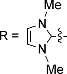
|
φ = 0.0039 | φ = 0.055 | |||
| τ = 0.6 μs5a | τ = 282 μs8b | ||||
| k nr = 1.66 × 10⁷ s–1 | k nr = 3.35 × 10³ s–1 | ||||
Interestingly, when the fluorenyl moiety is disposed in such a fashion that the long alkyl chains are “endo” in the gold(iii) pincer complex (last column in Table 1), there is a dramatic decrease in emission quantum yield (φ ∼ 0.02, τ ∼ 14.5 μs) and a nearly 40-fold increase in the non-radiative decay rate constant (knr ∼ 6.76 × 10⁴ s–1) when compared with its “exo” analogue (Table 1, column 5; see ESI† for the synthetic procedure and photophysical properties of the “endo” complex). This means that, even with a seemingly suitable cyclometalated ligand (i.e., a strong σ-donor which raises the energy of the dd or LMCT excited state and a cyclometalated ligand with extended π-conjugation that minimizes structural distortion), the phosphorescence efficiency of gold(iii) complexes is not necessarily high. Thus, for effective design of functional luminescent molecules, it is important to understand the effect of π-conjugation in the C-deprotonated cyclometalated [C^N^C] ligand on the excited state properties of these luminescent gold(iii) complexes.
In this work, we have performed a detailed theoretical analysis of four gold(iii) complexes with different [C^N^C] cyclometalated ligand scaffolds (Chart 1), namely, the non-conjugated CH^N^C (1) and the π-conjugated Cnp^N^C (2) and Cfl^N^C (3-exo and 3-endo); complexes 2 and 3-exo (and 3-endo) have one of the phenyl moieties of 1 replaced by a naphthalenyl (np) or a fluorenyl (fl) moiety respectively. The ancillary ligand, p-methoxyphenyl acetylide ([C CPh-4-OMe]–) is kept the same for all four complexes. A detailed list of definitions and abbreviations is provided in the appendix.
Chart 1.
Theoretical background
Dynamical solvent effect on excited state and ground state energies
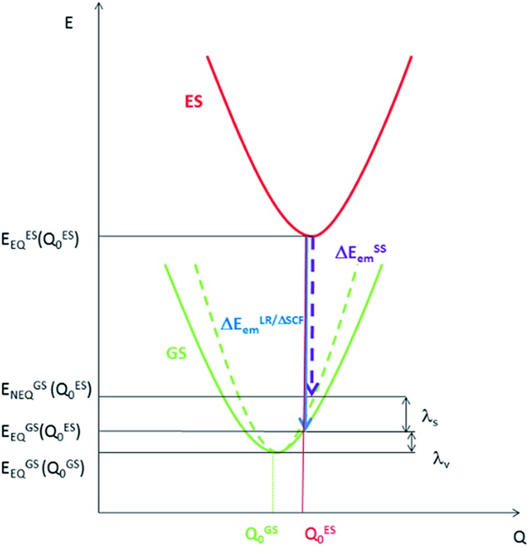
Density Functional Theory (DFT) and time-dependent DFT (TDDFT) are the commonly used tools to study the ground state and excited state properties of medium- to large-sized molecules. In the literature, computation of emission energies in solutions is performed using either linear response TDDFT (LR-TDDFT) or the ΔSCF method. For both types of calculations, both the excited state of interest and the ground state are calculated with equilibrium (EQ) solvation. However, in an emission process, the ground state should be treated with solvent polarization in the non-equilibrium (NEQ) regime10 because the time scale of an emission process is much faster than that of the solvent dynamics. Therefore, for a rigorous consideration of the solvent effect on an emission process, the ground state should be computed with non-equilibrium solvation, i.e., only the solvent electronic polarization (the “fast” component) is in equilibrium with the ground state electron density of the solute, while the solvent nuclear polarization (the “slow” component) remains equilibrated with the excited state electron density of the solute. For this reason, we have employed the state-specific (SS) approach to account for the dynamical solvent effect. Within the SS scheme, rather than using the ground state electronic density as in LR-TDDFT and ΔSCF, the electronic density of the emitting excited state is used to compute the ground state energy.10 Therefore, the emission energy within the SS scheme (ΔESSem) is given by:
| ΔESSem = EESEQ(QES0) – EGSNEQ(QES0) | 1 |
EESEQ(QES0) is the energy of the excited state (ES) with equilibrium solvation at the optimized excited state geometry (QES0), and EGSNEQ(QES0) is the energy of the ground state (GS) with non-equilibrium solvation at (QES0) (Fig. 1).11
Fig. 1. Potential energy surfaces for an electronic transition with energy evaluated with equilibrium solvation (solid line) and non-equilibrium solvation (dashed line).
The SS approach also allows one to estimate the solvent reorganization energy (λs), which is the ground state energy difference calculated with non-equilibrium solvation (EGSNEQ(QES0)) and with equilibrium solvation (EESEQ(QES0)) at the optimized excited state geometry (QES0) (Fig. 1):11
| λs = EGSNEQ(QES0) – EGSEQ(QES0) | 2 |
Similarly, the intramolecular reorganization energy computed within the SS approach (λSSV) is given by:
| λSSv = EGSEQ(QES0) – EGSEQ(QGS0) | 3 |
where EGSEQ(QGS0) is the energy of the ground state computed with equilibrium solvation at the optimized ground state geometry QGS0 (Fig. 1).
Radiative decay rate constant (kr)
The total radiative decay rate constant from the vibrational ground state of the emitting T1α-spin sub-state (krα) to the S0 state vibrational manifolds is given by the sum of individual radiative decay rate constants (denoted krα(ν̃)), each corresponding to a single vibronic transition, T1α(υ′ = 0) → S0(υ′′), with photon energy, ν̃, and vibrational quantum number for the T1 and S0 states, υ′ and υ′′, respectively:
 |
4 |
The radiative decay rate constant for the single vibronic transition can be calculated from the Einstein coefficient of spontaneous emission:12
 |
5 |
where η is the solvent refractive index, ν̃ is the triplet emission energy (in cm–1), and MTα(Q) is the transition dipole moment of the T1α → S0 transition (in ea0), and the prefactor 8π2/3ε0ħ = 2.0261 × 10⁻⁶.
By invoking the Condon approximation (i.e., MTα(Q) ≈ MTα(QT10) with QT10 being the optimized T1 excited state geometry) and combining eqn (4) and (5), the total radiative decay rate constant, krα, is given by:13
 |
6 |
χυ′′ and χυ′ are the vibrational wavefunctions of the S0 and the T1 states respectively.
Unless the emission spectrum is sharply peaked, as in an atomic emission spectrum, one should not take the integral in eqn (6) as unity and replace the summation in eqn (6) by the emission peak maximum, ν̃max3; such an approximation is justified only if the molecule has fixed nuclei. In reality, however, the nuclei are in motion, bringing about a broadening of the emission spectrum. These nuclear motions (i.e., vibrations) can be accounted for by the Franck–Condon factors ((|∫χ*υ′′χυ′dQ|2). In general, one may approximate the last term in the summation as:13
 |
7 |
with I(ν̃) being the emission intensity at ν̃ (corrected to the number of photons emitted per unit wavenumber). The emission intensity can be obtained either from experiment or by computational simulation. The total radiative decay rate constant for the T1α → S0 transition may then be written as:
 |
8 |
The transition dipole moment MTα(QT10) could be obtained by first-order perturbation interactions between the T1α-spin sub-state and the singlet excited state via spin–orbit coupling (SOC):12
 |
9 |
where MSm,j is the j-axis projection of the Sm → S0 transition dipole moment, E(T1) and E(Sm) are the energies of the T1 and the mth singlet (Sm) excited states, respectively, and T1α|HSOC|Sm are the SOC matrix elements between the T1α-spin sub-state and the Sm excited state.
As the energy splitting between the three T1α-spin sub-states is less than 5 cm–1, all sub-states should be equally populated at room temperature. Therefore, the average radiative decay rate constant kr is given by:
 |
10 |
Non-radiative decay rate constant (knr)
In the limit of the Franck–Condon approximation in the non-adiabatic regime, the non-radiative decay rate constant (knr) of the T1 → S0 transition can be estimated by application of the Fermi's Golden Rule expression, assuming that both electronic states are harmonic:14
 |
11 |
This expression can be applied when ħωM ≫ kBT and the solvent orientational and librational motions are treated classically. ωM are the high-frequency (hf) intraligand vibrational modes (ħωM > 1000 cm–1), typically corresponding to the aromatic CC/CN stretching modes (ħωM ∼ 1200–1500 cm–1) and C C stretching modes (ħωC C ∼ 2200–2300 cm–1) if the acetylide ligand is involved in the complex; λS is the solvent reorganization energy and may be obtained from eqn (2); ΔE is given by
| ΔE = ΔE00 – λlf | 12a |
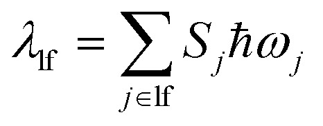
with ΔE00 being the zero-point energy difference between the T1 and S0 states and λlf being the reorganization energy contributed by the low-frequency (lf) modes of the complex (i.e., ħωlf < 1000 cm–1). Assuming that all the normal modes are harmonic oscillators,
 |
12b |
 |
12c |
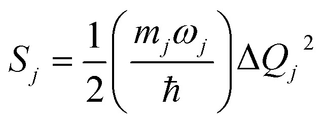
Sj, mj, and ΔQj are the Huang–Rhys factor, the reduced mass, and the equilibrium displacement of the jth normal mode ωj, respectively; SM and nM are the Huang–Rhys factor and the number of quanta of the effective high frequency mode ħωM (corrected to the nearest integer), respectively:
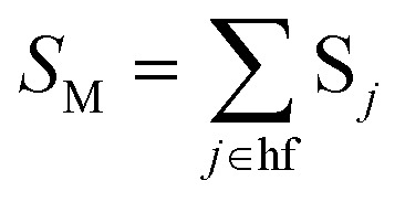 |
12d |
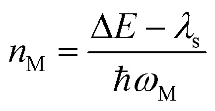 |
12e |
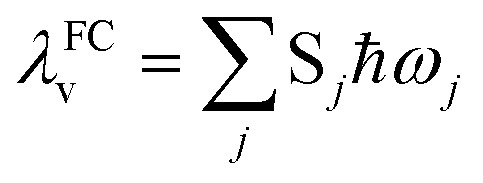
Under the harmonic oscillator approximation, the intramolecular reorganization energy, λFCv, could be estimated as:
 |
13 |
where the summation runs over all the normal modes, ωj.
Computational details
In this work, the hybrid density functional, PBE0,15 was employed for all calculations using the program package G09.16 The 6-31G* basis set17 was used for all atoms except Au, which was described by the Stuttgart relativistic pseudopotential and its accompanying basis set (ECP60MWB).18 The solvent effect was also included by means of the polarizable continuum model (PCM) with the solvent as dichloromethane (CH2Cl2; η = 1.424).19 Geometry optimizations of the singlet ground state (S0) and the lowest triplet excited state (T1) were respectively carried out using restricted and unrestricted density functional theory (i.e., RDFT and UDFT) formalisms without symmetry constraints. Frequency calculations were performed on the optimized structures to ensure that they were minimum energy structures by the absence of imaginary frequency (i.e., NImag = 0). Stability calculations were also performed for all the optimized structures to ensure that all the wavefunctions obtained were stable.
Vertical transition energies were computed using the linear response approximation for absorption, but the state specific approach for emission.20 For the radiative decay rate constant calculation (using eqn (8) and (9)), the singlet excited state energy, E(Sm), the associated transition dipole moment of the Sm → S0 transition MSm,j (j = x, y, z), and the coefficients necessary to compute the SOC matrix elements (i.e., the d-orbital coefficients (cd) of Au in the MO relevant to the coupling excited states and the corresponding CI coefficients), were all obtained from a state-specific approach using “ExternalIteration” implemented in G09.10b,20
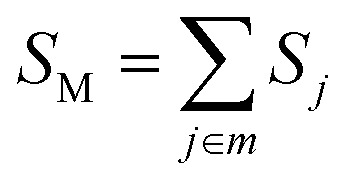
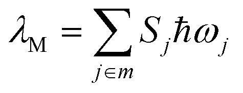
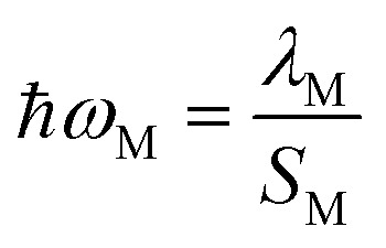
The Huang–Rhys factor Sj (using eqn (12c)) for the normal mode ωj may be obtained by performing a Franck–Condon calculation implemented in G09 via “freq = fc” and “prtmat = 2”. The simulated emission spectrum allows one to calculate the Franck–Condon factor-weighted emission energy ν̃fcf (using eqn (7)). The high-frequency normal modes (1000 < ħωm ≤ 1800 cm–1) can be characterized by a mean frequency ωM and an effective electron-phonon coupling strength (or Huang-Rhys factor) SM:21
 |
14a |
 |
14b |
 |
14c |
Further computational details can be found in the ESI.†
Results and discussion
Ground state structures and absorption energies
In general, the optimized ground state structures of 1, 3-exo, and 3-endo are in good agreement with the X-ray crystallography data (<0.05 Å and 8.5°) except for the dihedral angle between the planes of the [C^N^C] ligand and the phenyl ring of the acetylide ligand (δ); calculations revealed a nearly coplanar geometry (δ ∼ 5.7° and –0.27° for 1 and 3-exo respectively) whereas experimentally determined δ values are 66.1° and 54° respectively.3a,5b Similarly, though DFT calculations predict a non-coplanar geometry for the ground state of 3-endo (δ ∼ 130°), the corresponding X-ray data is only ∼59° (see ESI† for the X-ray data and DFT results for 3-endo). In addition, the Au–C(acetylide) distance for 1 was calculated to be 1.950 Å while the corresponding distance from the crystallography data is 2.009 Å.5b It should be noted that the Au–C(acetylide) distances reported for similar [(CH^N^C)AuIIIC CPh-4-Y] (Y is a substituent) complexes are in the range of 1.945–1.980 Å;5b our calculated value falls within this range. It is thus possible that the discrepancies between experimental and calculated geometries are due to the crystal packing effect.
Table 2 presents the absorption energies of low-lying singlet excited states at the respective optimized S0 geometries of the four complexes studied herein. A full list of the TDDFT results can be found in the ESI.† In general, the calculated absorption energies are in good agreement with the corresponding experimental absorption peak maxima. Previous TD-B3LYP/CPCM calculations also suggest that the lowest absorption peak of 1 is 1LLCT in nature (LLCT = ligand-to-ligand charge transfer), with a calculated vertical excitation energy at λ = 408 nm (f = 0.23).5b
Table 2. Singlet excited state energies (λ in nm) and the associated oscillator strengths (f), together with the nature of singlet excited states of the four complexes depicted in Chart 1 at their respective optimized S0 geometries. μGS(D) is the ground state dipole moment obtained from DFT calculations. The experimental values (λexp in nm) are listed in the last column.
| Complexes | Sm | λ | F | Nature a | μ GS | λ exp |
| 1 | S1 | 392 | 0.251 | 1LLCT | 6.13 | 400, 380, 362 |
| S2 | 367 | 0.0519 | 1ππ*(CH^N^C) | |||
| 2 | S1 | 401 | 0.2737 | 1LLCT | 8.36 | 396, 380 |
| S2 | 370 | 0.2623 | 1ππ*(Cnp^N^C) | |||
| 3-exo | S1 | 409 | 0.1645 | 1ππ*(Cfl^N^C)/1LLCT | 8.09 | 428, 409 |
| S2 | 401 | 0.3078 | 1LLCT/1ππ*(Cfl^N^C) | |||
| 3-endo | S1 | 426 | 0.0671 | 1LLCT | 8.09 | 430, 409 |
| S2 | 407 | 0.2505 | 1ππ*(Cfl^N^C) |
aAll the singlet excited states have some metal character, but generally less than 10%.
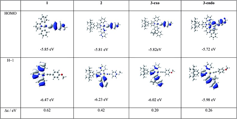
As depicted in Table 2, the most conspicuous difference among the four complexes is that, except for 3-exo, the first singlet excited state (S1) is a 1LLCT excited state, derived mainly from the HOMO → LUMO transition, 1[π(C CPh-4-OMe) → π*(C^N^C)] (Fig. 2 and ESI† for the MO surfaces). On the other hand, for 3-exo, the S1 state is predominantly intraligand (IL) in character (>80%); this 1IL excited state is derived from the H – 1 → LUMO transition and is a 1ππ*(C^N^C) excited state. The difference in the nature of the S1 excited state among the four complexes can be rationalized as follows: upon increasing the π-conjugation along the series 1, 2, 3-endo, and 3-exo, H – 1 is destabilized and the MO splitting (Δε) between HOMO and H – 1 decreases from 0.62 eV (1) to 0.26 eV (3-endo) and 0.20 eV (3-exo), (Fig. 2). This decrease in MO splitting results in a decrease in the contribution of the HOMO → LUMO transition to the S1 state, but a concomitant increase in percentage of the H – 1 → LUMO transition (Table S9†). As a result, the predominant contribution to the S1 state is mainly 1LLCT in character for 1, 2, and 3-endo, while for 3-exo, the S1 state is mainly 1IL in nature. This decrease in MO splitting not only affects the nature of the lowest singlet excited state, but also significantly impacts the emitting excited state, as described in a later section.
Fig. 2. Frontier MOs of the four complexes at their respective optimized S0 geometries together with the HOMO/H – 1 MO splitting, Δε.
T1 excited state: radiative and non-radiative decay rates
The experimental photophysical data regarding the emissions of the four gold(iii) complexes are listed in Table 3.
Table 3. Experimental emission maxima (λmax nm–1), quantum yields (φ) and lifetimes (τ μs–1) of the four complexes measured in dichloromethane solutions at 298 K. Radiative (kr) and non-radiative (knr) decay rates are obtained from kr = φ/τ and knr = 1/τ – kr and are tabulated in units of (×103 s–1).
| λ max | φ | τ | k r | k nr | |
| 1 (ref. 3a and 5b) | 474 | 0.0004 | 0.017 | 23.5 | 58 800 |
| 2 (ref. 8a) | 562 | 0.09 | 25 | 3.60 | 36.4 |
| 3-exo (ref. 3a) | 538 | 0.58 | 242 | 2.40 | 1.74 |
| 3-endo a | 536 | 0.02 | 14.5 | 1.38 | 67.6 |
aThis work, ESI.†
As depicted in Table 3, 1 has the fastest radiative and non-radiative decay rate constants, with the latter being more than 800-fold faster than that of the other three complexes. Complex 3-exo displays the slowest knr among the four complexes studied herein, while the associated kr is comparable to the other two complexes with π-conjugation at the [C^N^C] cyclometalated ligand (i.e., 2 and 3-endo).
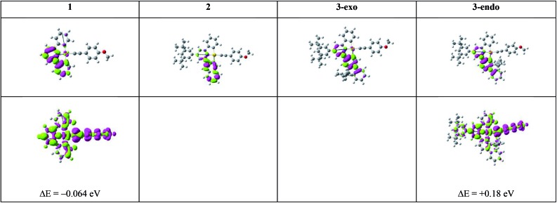
To understand the emission properties of the four complexes depicted in Chart 1, we have employed unrestricted DFT (UDFT) to optimize their lowest triplet excited states. For 2 and 3-exo, only one triplet excited state, 3ππ*(C^N^C) IL excited state, was found. On the other hand, two triplet excited state minima, one 3IL in character and the other 3LLCT (3[π(C CPh-4-OMe) → π*(C^N^C)]), were found for both 1 and 3-endo. The electron difference density maps (eddms) for the calculated triplet excited states, together with the relative energy splitting between the 3IL and 3LLCT excited states for complexes 1 and 3-endo, are presented in Fig. 3.
Fig. 3. Electron difference density maps (eddms) as obtained from SS-TDDFT calculations at their respective optimized T1 excited state geometries for the four complexes in Chart 1 (isovalue = 0.001 a.u.). The upper row depicts the 3IL excited states while the bottom row presents the 3LLCT excited states. The 3IL excited state is set as the reference point, i.e., ΔE (in eV) is the energy of the 3LLCT excited state relative to that of the 3IL excited state of a complex obtained from UDFT calculations. Colour scheme: moss green represents increased electron density; magenta represents decreased electron density.
Table 4 lists the computed 0–0 transition energies (ΔE00), vertical emission energies (ΔESSem, Fig. 1), Franck–Condon factor-weighted emission energies (ν̃fcf), and radiative decay rate constants of the optimized T1 excited states of the four gold(iii) complexes studied herein.
Table 4. Computed 0–0 transition energy (ΔE00 in nm), vertical emission energy (ΔESSem in nm), Franck–Condon-factor weighted emission energy (ν̃fcf in nm), and radiative decay rate constants (kr× 103 s–1) for the four gold(iii) complexes a .
| ΔE00 | ΔESSem |
ν̃ fcf | k r b | |||
| SCF | SS-TDDFT | |||||
| 1 | 3IL | 484 | 534 | 612 | 555 | 6.12 (8.28) |
| 3LLCT | 492 | 586 | 1832 | — c | 0.018 | |
| 2 | 3IL | 541 | 593 | 704 | 618 | 0.148 (0.219) |
| 3-exo | 3IL | 554 | 610 | 698 | 621 | 0.544 (0.772) |
| 3-endo | 3IL | 550 | 604 | 691 | 612 | 0.353 (0.507) |
| 3LLCT | 510 | 601 | 1570 | — c | 0.047 | |
aΔESSem is obtained from two different methods: (1) in the SCF method, it is the energy difference between the T1 excited state calculated with equilibrium solvation at the UDFT level and the S0 ground state with non-equilibrium solvation with the T1 excited state electron density using DFT; (2) in the SS-TDDFT method, it is the pole of the T1 excited state from a SS-TDDFT calculation with PCM correction; ν̃fcf is obtained from eqn (7) using the emission spectrum generated from a Franck–Condon calculation implemented in G09 (for details, see above and ESI†); kr is the radiative decay rate constant obtained by considering only the lowest singlet excited state(s) that can have effective SOC with the T1 excited state (see ESI† for further computational details).
bThe value outside the parentheses corresponds to the radiative decay rate constant obtained using SS-TDDFT ΔESSem while that inside the parentheses corresponds to that obtained using ν̃fcf.
cFC simulated spectrum is unreliable; and therefore ν̃fcf cannot be determined in such a case.
(i). Emission energies
With the exception of 2, there is generally a close correlation between the experimental solution emission maxima (λmax) at room temperature and the calculated ΔE00 of the 3IL excited states of the gold(iii) complexes in Chart 1. This suggests that for complexes 1, 3-exo, and 3-endo, the emission maximum may correspond to the 0–0 transition of 3IL → S0. The experimental emission maximum of 2 is at a lower energy than that of 3-exo (Table 3). For related platinum(ii) [C^N^C] cyclometalated complexes, the one with a naphthalene moiety at the [C^N^C] ligand displays a higher energy emission peak than the one with a fluorene unit (e.g., complexes 7 and 8 in ref. 9) and the emitting triplet excited state is assigned as having a mixed 3IL/3MLCT character (MLCT = metal-to-ligand charge transfer).9 Our present theoretical analysis is in accordance with these findings on the platinum(ii) [C^N^C] cyclometalated complexes: ΔE00 of the gold(iii) complexes is in the order 1 > 2 > 3-endo ∼ 3-exo. This trend is a manifestation of the increase in π-conjugation at the [C^N^C] cyclometalated ligand when one goes from 1 to 2 to 3-endo and 3-exo. Increasing π-conjugation destabilizes the π(C^N^C) orbital, (see also Fig. 2), thereby decreasing the MO splitting between π(C^N^C) and π*(C^N^C) orbitals and leading to a red shift in emission energy of the 3IL excited state from 1 to 2 to 3-endo and 3-exo. The fact that the experimental emission maximum of 2 is lower in energy than those of 3-exo and 3-endo may reflect that the emission peak maximum of 2 may not correspond to the 0–0 transition; it may suggest that the structural distortion between the T1 and S0 states of 2 is larger than that of 3-exo and 3-endo (vide infra).
(ii). Radiative decay rate constants
Table 4 presents the radiative decay rate constants calculated for each of the T1 excited states of the four complexes. Although the kr values of the 3IL excited states are slightly underestimated by a factor of ∼2.7–3.1, they are consistent with the experimental kr values except in the case of 2 (compare Tables 3 with 4). The calculations indicate that 2 should have the slowest radiative decay rate constant, which is not supported by the photophysical data recorded at room temperature (Table 3). However, it was reported that the emission lifetime of 2 increases from 25 μs at room temperature to 2285 μs in a glassy medium at 77 K.8a Assuming that this lifetime corresponds to the radiative lifetime, kr would be estimated to have a maximum value of ∼438 s–1. This is close to our theoretical results, i.e., the 3IL excited state of 2 should have the slowest radiative decay rate constant among the four gold(iii) complexes (as a reference, the kr estimated in the same way as that of 2 at 77 K would be 7.30 × 10³, 3.55 × 10³, and 2.46 × 10³ s–1 for 1, 3-exo, and 3-endo respectively).3a,5b It is conceivable that the emission of 2 at 298 K and 77 K originated from different excited states. However, no other triplet excited state minimum was found for complex 2 using the present DFT/TDDFT method.
(iii). Non-radiative decay rate constants
Table 5 lists the calculated results related to the non-radiative decay rate constants. First, let us consider the 3IL excited states of the four gold(iii) complexes. As depicted in Table 5, the Huang–Rhys factors (SM) are in the order: 1 > 2 > 3-exo ∼ 3-endo. This trend is in line with the S0 to T1 structural distortion of the following organic molecules in the order: benzene > naphthalene > carbazole (carbazole is isoelectronic to fluorene).22 These two trends are similar because the 3IL excited states of these four gold(iii) complexes are mainly localized on the phenyl, naphthalenyl, and fluorenyl moieties, respectively (Fig. 3). As the Huang–Rhys factor serves to quantify the structural distortion between the emitting triplet excited state and the ground state, the smallest values of SM for 3-exo and 3-endo reveal that the fluorene unit at the [C^N^C] cyclometalated ligand imparts the greatest rigidity to the complex. In other words, the rigidity of the organic moiety at the pincer-type cyclometalated ligand could qualitatively account for the experimental results that 1 has the fastest non-radiative decay rate constant and 3-exo the slowest.
Table 5. Effective Huang–Rhys factors (SM) for the high-frequency mode, intramolecular (λv) and solvent (λs) reorganization energies (in cm–1), dipole moments of the T1 excited state (μT1/D), T1|HSOC|S02 (in cm–2), Franck–Condon Factors (FCF), and non-radiative decay rate constants (knr × 103 s–1) for the four complexes studied herein.
| S M a |
λ
v
b
|
λ s | μ T1 | T1|HSOC|S02 | FCF e | k nr | |||
| SS | FC | ||||||||
| 1 | 3IL | 1.75 | 2889 | 2920 | 21.2 | 6.23 | 943 | 2.66 | 2.508 |
| 3LLCT | 0.11 c | 2090 | n.a. | 1980 | 16.3 | 1757 | 989 d | 1738 | |
| 2 | 3IL | 1.47 | 2622 | 2618 | 62.72 | 8.36 | 148 | 151 | 22.35 |
| 3-exo | 3IL | 1.29 | 2392 | 2408 | 75.74 | 7.21 | 323 | 9.74 | 3.146 |
| 3-endo | 3IL | 1.27 | 2388 | 2439 | 83.24 | 6.29 | 173 | 7.24 | 1.253 |
| 3LLCT | 0.22 c | 2051 | n.a. | 1812 | 18.5 | 1664 | 1130 d | 1880 | |
a S M corresponds to the effective Huang–Rhys factor of the high-frequency (hf) modes in the range 1000 ≤ ωm ≤ 1800 cm–1 when the T1 excited state is 3IL.
bThe intramolecular reorganization energy λv was obtained in two different ways: state specific (SS; eqn (3)) and Franck–Condon (FC; eqn (13)).
c S M = SC, i.e., the Huang–Rhys factor of the C C stretching mode, ωC C (see ESI† for details).
dEstimated under the assumption that the Huang–Rhys factors of the 3LLCT → S0 transition are the same as those of the 3IL → S0 of the same complex, together with the Huang–Rhys factor of the C C stretching normal mode.
eThe term 2π/ħ is absorbed into the FCF.
Besides, the magnitude of the SOC matrix element between the 3IL excited state and S0 ground state follows the order: 1 > 3-exo > 3-endo > 2. At their respective optimized 3IL excited states, the metal contributions (expressed as cd2) to the H – 1 (HOMO for 3-exo and 3-endo), at their optimized T1 geometries, are 4.18 (1), 0.36 (2), 1.94 (3-exo), and 1.07 (3-endo), respectively. As SOC is mainly brought about by the gold(iii) ion, the larger the coefficient of Au(d) in the H – 1/HOMO, the larger should be the SOC matrix element, 3IL|HSOC|S02. The Au(d) character in the H – 1/HOMO of the gold(iii) complexes studied herein is related to the nature of the HOMO of the C-deprotonated moiety in the [C^N^C] ligand. For complex 2, the H – 1 is mainly localized on the long molecular axis of the naphthalene fragment (Fig. 2), thus rendering the [Cnp^N^C] ligand to have little interaction with the gold(iii) ion and therefore, the smallest cd in the H – 1 orbital of 2. On the other hand, the corresponding orbital of complex 3-exo is along the short molecular axis of the fluorene fragment, thus the [Cfl^N^C] ligand could have a stronger interaction with the gold(iii) ion, and hence, a larger cd in the HOMOs of complexes 3-exo and 3-endo.
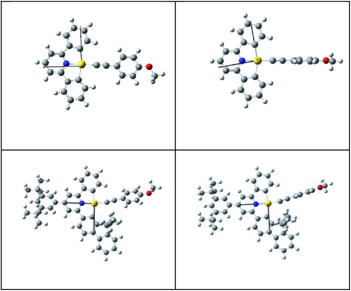
Although both the effective Huang–Rhys factor SM and the SOC between the T1 and S0 states are largest for 1, the calculated non-radiative decay rate constant knr for the 3IL → S0 transition is smaller than that of 3-exo, a result contrary to the order of experimental knr values; knr(calc): 2 > 3-exo > 1; knr(expt): 1 ≫ 2 > 3-exo. This is because 1 has a much larger energy gap between the 3IL and S0 states than the other three gold(iii) complexes (Table 4), making the energy gap effect play a dominant role in determining the knr (3IL → S0) of 1. Similarly, the calculated non-radiative decay rate constant for 3-endo is ∼1.25 × 10³ s–1, which is also smaller than that of 3-exo, and is inconsistent with the experimental data (compare Tables 3 and 5). For these two complexes, 1 and 3-endo, an additional triplet excited state minimum was found (Fig. 3). This triplet excited state, as observed from the eddms in Fig. 3, is best characterized to be a 3LLCT, 3[π(C CPh-4-OMe) → π*(C^N^C)], excited state. This 3LLCT excited state displays a large amplitude motion along the dihedral angle between the [C^N^C] plane and the arylacetylide plane (δ): from ∼–4.132° (S0) to –88.739° (3LLCT) for 1 and from 130.381° (S0) to 92.352° (3LLCT) for 3-endo (see Fig. 4 for the optimized structures of the S0 and 3LLCT excited states for complexes 1 and 3-endo). Because of this large amplitude motion, we refrained from performing a Franck–Condon calculation on the 3LLCT → S0 transition, as we have performed for that of the 3IL → S0. This is because, for the Franck–Condon calculation implemented in G09, the normal modes are represented in Cartesian coordinates. Cartesian coordinates are inadequate to describe large amplitude motions, such as torsions, as this could lead to artificial bond breaking and bond forming at its extreme.23 For instance, due to the rotation of the phenyl group at the arylacetylide ligand relative to the [C^N^C] plane, the C–H bonds on the phenyl ring of the arylacetylide ligand would be artificially broken if Cartesian coordinates were used to describe the normal modes. This could result in erroneously large Huang–Rhys factors for the C–H stretching modes. However, in reality, there is no C–H bond breaking when one goes from the 3LLCT to the S0 state. Moreover, such fictitious bond breaking and bond forming will lead to a diffuse Duschinsky matrix, which could lead to an incorrect interpretation of the fast non-radiative decay rate constant due to a large Duschinsky effect.
Fig. 4. Optimized structures of the S0 (left) and 3LLCT excited states for 1 (top) and 3-endo (bottom).
Nevertheless, the C C stretching normal mode is decoupled from the other normal modes, as reflected by the Duschinsky matrix elements of the 3LLCT → S0 transition; ωC C is the only normal mode that has the diagonal matrix element equal to 1. Therefore, we estimated the non-radiative decay rate constants of the 3LLCT excited state by replacing all the Huang–Rhys factors (Sj) of the 3LLCT → S0 transition with those of the 3IL → S0 transition, but keeping the Huang–Rhys factor of the C C stretching normal mode from a Franck–Condon calculation of the 3LLCT → S0 transition. Such an assumption is based on the fact that both the 3LLCT and 3IL excited states of the gold(iii) complexes involve changes in electron density at the [C^N^C] ligand.
From Table 5, several points concerning the 3LLCT excited states of 1 and 3-endo are noted: (a) The solvent reorganization energy (λS) of 3LLCT is much larger than that of 3IL. This is attributed to the dipole moment of the 3LLCT being much larger than that of 3IL and the ground states (see Table 5 for the excited state dipole moments (μT1) and Table 2 for the ground state dipole moments (μGS)). In the framework of the SS approach, solvent reorganization energy is proportional to the square of the difference in dipole moments between the T1 excited state and the S0 ground state, i.e., λs ∝ (μT1 – μGS)2.20 Therefore, this large solvent reorganization effectively leads to a decrease in the energy gap between the 3LLCT and the S0 potential energy surfaces (PESs) at the equilibrium geometry of the 3LLCT excited state. Thus, fewer quanta of the high-frequency vibrational mode (nM) are needed (see eqn (12e)) and the activation energy (the temperature-dependent term in the last exponential of eqn (11)) is smaller as this energy term is inversely proportional to the solvent reorganization energy; (b) the square of the HSOC matrix element between the 3LLCT excited state and the S0 ground state is larger than that between the 3IL excited state and the ground state (Table 5).
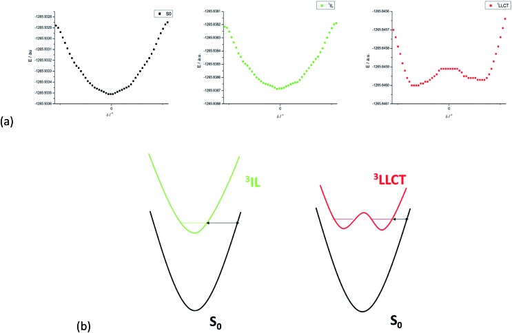
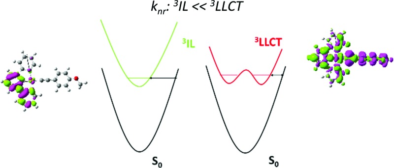
The non-radiative decay rate constants thus estimated for the 3LLCT excited states of 1 and 3-endo are 1.738 × 10⁶ and 1.880 × 10⁶ s–1, respectively, more than 690-fold and over 1500-fold larger than those of their respective 3IL excited states. These non-radiative decay rate constants may still be underestimated since the structural change associated with the torsional motion between the [C^N^C] and arylacetylide ligands has not been included in the Franck–Condon factor (FCF) calculation of the 3LLCT → S0 transition. (We have used the Huang–Rhys factor of the 3IL → S0 transition where there is no such large amplitude torsion.) We have undertaken a rigid scan along the torsional coordinate (δ) for 1. Fig. 5a displays the PESs along the torsional coordinate δ for the ground state, 3IL excited state, and 3LLCT excited state of complex 1. The potential energy minimum is roughly harmonic for both the ground state and the 3IL excited state but anharmonic for 3LLCT excited state. As the 3LLCT excited state has a double minimum potential while the ground state is approximately harmonic, the Franck–Condon factor (FCF) between 3LLCT and S0 is expected to be larger than that between the 3IL and S0 states, where both PESs are harmonic along the torsion coordinate δ. This may be rationalized as illustrated in Fig. 5b. The “barrier width” (indicated by the double arrow in Fig. 5b), being qualitatively related to the FCF in an inverse manner, is smaller for a potential energy surface with a double minimum potential (as in 3LLCT excited state) than that with a harmonic PES (as in 3IL excited state; Fig. 5b).24 Thus, the non-radiative decay rate of the 3LLCT → S0 transition should be further enhanced due to the increase in the FCF brought about by the torsional motion. In addition, there would be a strong thermal quenching of phosphorescence because thermal excitation of the torsional normal mode in the 3LLCT excited state would decrease the “barrier width”, leading to a significant increase in the FCFs, and, hence, a further enhancement of the non-radiative decay rate.
Fig. 5. (a) Potential energy surface (PES) of 1 along the torsion coordinate (δ) for the S0 state (left), 3IL excited state (middle), and 3LLCT excited state (right). (b) The left-hand PESs depict the case when both PESs in a transition are harmonic and the right-hand PESs represent the case when the emitting excited state has a double minimum PES; the double arrow indicates the “barrier width” and it is smaller for the right-hand case than the left-hand case.
If one supposes that the torsional motion increases the FCF of the 3LLCT → S0 transition by a factor of ∼10, the values of knr for 1 and 3-endo for this transition would be ∼1.7 × 10⁷ and ∼1.9 × 10⁷ s–1, respectively. We may then re-estimate the non-radiative decay rate constants by taking into consideration both the 3LLCT and 3IL excited states with Boltzmann populations. As 3LLCT is calculated to be ∼500 cm–1below3IL for complex 1, the re-estimated non-radiative decay rate constant for complex 1 at room temperature is comparable to the experimental value (knr(calc) ∼ 1.6 × 10⁷ s–1 and knr(expt) ∼ 5.9 × 10⁷ s–1). In other words, the major deactivating channel for the emissive excited state of 1 is not 3dd or 3LMCT, as is usually ascribed to efficient non-radiative decay for luminescent transition metal complexes, but 3LLCT due to a large SOC, a large solvent reorganization energy, and the non-planar torsional motion between the [C^N^C] and arylacetylide ligands. For 3-endo, the 3LLCT excited state is calculated to be ∼1400 cm–1above that of the 3IL state. Therefore, the re-estimated knr becomes ∼1.5 × 10⁴ s–1, which is in good agreement with the values derived from the experimental measurements in solutions at 298 K (knr(expt) ∼6.8 × 10⁴ s–1).
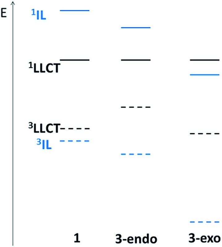
Based on the above analyses on non-radiative decay rate constants, it is the presence of the close-lying 3LLCT excited state that contributes to the very fast non-radiative decay rate. The relative order of the 3LLCT and 3IL excited states would thus be important in determining the phosphorescence efficiency. In the present series of gold(iii) complexes, this relative order can be understood from the relative energies of the π(C^N^C) and π(C CPh-4-OMe) MOs. As the LLCT excited state is a charge transfer excited state, while the IL excited state is localized, the singlet–triplet splitting of LLCT excited states (E(1LLCT)–E(3LLCT)) would be smaller than that of IL excited states (E(1IL)–E(3IL)). In the case of 1, due to the large orbital energy difference (Δε) between the π(CH^N^C) and π(C CPh-4-OMe) MOs (Fig. 2), the 1IL excited state is much higher in energy than that of the 1LLCT excited state. Thus, the splitting of the 3IL and 3LLCT states is the smallest (see Fig. 6 for a schematic illustration). For 3-endo, as the corresponding Δε is smaller than that of 1, the 1LLCT is only slightly lower in energy than the 1IL excited state such that the 3IL–3LLCT energy gap widens. For 3-exo, as the lowest singlet excited state is predominantly IL in character, the 3IL–3LLCT energy gap is even wider. In fact, we have not been able to locate a T1 minimum corresponding to a 3LLCT excited state (Fig. 6).
Fig. 6. Schematic representation of the relative 3LLCT–1LLCT and 3IL–1IL splittings for 1 (left), 3-endo (middle), and 3-exo (right). The solid curve corresponds to a singlet excited state while the dashed line a triplet excited state. The colours black and blue represent the LLCT and IL excited states, respectively.
Based on the above rationale, it is speculated that the 3IL–3LLCT gap of 2 should fall between that of 1 and 3-endo, as deduced from the relative order of the π(Cnp^N^C) and π(C CPh-4-OMe) MOs depicted in Fig. 2. Indeed, an energy minimum of a 3LLCT excited state was located in the course of LR-TDDFT optimization; subsequent SS-TDDFT calculation at this geometry showed that this 3LLCT excited state is lower-lying than the 3IL one. However, global hybrid density functionals, (e.g., PBE0, a functional that we have employed in the present work) generally underestimate the energy of charge transfer excited states within the TDDFT framework. Thus, we performed UDFT optimization starting from these TDDFT-optimized structures (which have a stable wavefunction) to see if there is a 3LLCT excited state minimum. Unfortunately, UDFT optimization starting from the TDDFT-optimized 3LLCT excited state went back to the 3IL excited state. It is likely that this 3LLCT excited state is metastable and exhibits vibronic coupling with other close-lying excited states.
Conclusions
We have carried out a detailed theoretical study on four gold(iii) [C^N^C] cyclometalated complexes with different extents of π-conjugation. It is commonly prescribed that a rigid ligand in a transition metal complex can minimize structural distortion between the emitting triplet excited state and the ground state, thereby decreasing the non-radiative decay rate. Franck–Condon analyses on the 3ππ*(C^N^C) IL → S0 transitions of the four gold(iii) complexes confirmed that an increase in π-conjugation at the [C^N^C] cyclometalated ligand results in a more rigid transition metal complex, as reflected by the effective Huang–Rhys factor, SM: 1 > 2 > 3-exo and 3-endo. Although this trend correlates with the experimentally determined non-radiative rate constants, 1 ≫ 2 > 3-exo, the calculated knr of the 3IL → S0 transition is inconsistent with the experimental data if one also takes into consideration the 3IL–S0 energy gap. DFT/TDDFT calculations reveal that there is an additional triplet excited state minimum, 3[π(C CPh-4-OMe) → π*(C^N^C)] LLCT, for complexes 1 and 3-endo, but not for 3-exo. It was found that the non-radiative decay rate constant for this 3LLCT → S0 transition exceeds 107 s–1, which is more than three orders of magnitude faster than the knr for the 3IL → S0 transition. More importantly, if the relative splitting between the 3LLCT and 3IL excited states was included in estimating the knr of complexes 1 and 3-endo, the calculated and experimental knr are in quantitative agreement. Based on the analysis of the relative order of π(C^N^C) and π(C CPh-4-OMe) MOs, one could rationalize why complexes 1 and 3-endo, but not 3-exo, have low-lying 3LLCT excited states. Our present analysis highlights the importance of the relative order of the frontier MOs of the coordinating ligands in multi-chromophoric transition metal complexes in designing strongly luminescent transition metal complexes. It also challenges the presumption that the low phosphorescence efficiency of transition metal complexes is due to the close proximity of the dd ligand-field state to the emitting triplet excited state.
Appendix
List of definitions, abbreviations, and symbols.
| Abbreviation | Definition |
| IL | Intraligand |
| LLCT | Ligand-to-ligand charge transfer |
| LMCT | Ligand-to-metal charge transfer |
| MLCT | Metal-to-ligand charge transfer |
| SOC | Spin–orbit coupling |
| LR | Linear response |
| SS | State-specific |
| EQ | Equilibrium |
| NEQ | Non-equilibrium |
| PCM | Polarizable continuum model |
| FCF | Franck–Condon factor |
| PES | Potential energy surface |
| Expt | Experimental |
| Calc | Calculated |
| eddm | Electron difference density map |
| μ GS | Dipole moment of the ground state |
| μ T1 | Dipole moment of the T1 excited state |
| c d | Coefficient of Au(d-orbital) |
| Q GS 0 | Optimized ground state (GS) geometry |
| Q ES 0 | Optimized excited state (ES) geometry |
| ΔESSem | Emission energy evaluated within the state-specific (SS) approach; eqn (1), Fig. 1 |
| E ES EQ (QES0) | Energy of the excited state (ES) with equilibrium (EQ) solvation at the optimized excited state geometry, Fig. 1 |
| E GS NEQ (QES0) | Energy of the ground state (GS) with non-equilibrium (NEQ) solvation at the optimized excited state geometry, Fig. 1 |
| E GS EQ (QES0) | Energy of the ground state (GS) with equilibrium (EQ) solvation at the optimized excited state geometry, Fig. 1 |
| E GS EQ (QGS0) | Energy of the ground state (GS) with equilibrium (EQ) solvation at the optimized ground state geometry, Fig. 1 |
| λ s | Solvent reorganization energy; eqn (2) |
| λ SS V | Intramolecular reorganization energy evaluated within the state-specific (SS) approach; eqn (3) |
| λ FC V | Intramolecular reorganization energy obtained from Franck–Condon (FC) calculation; eqn (13) |
| υ′ | Vibrational quantum number of the first triplet (T1) excited state |
| υ′′ | Vibrational quantum number of the ground state (S0) |
| χ υ′ | Vibrational wavefunction of the T1 excited state |
| χ υ′′ | Vibrational wavefunction of the ground state |
| η | Solvent refractive index |
| M T α (Q) | Transition dipole moment of the T1α → S0 transition at geometry, Q |
| M T α (QT10) | Transition dipole moment of the T1α → S0 transition evaluated at the optimized T1 geometry, QT10; eqn (9) |
| M Sm, j(QT10) | j-axis projection of the transition dipole moment of the Sm → S0 transition evaluated at the optimized T1 geometry, QT10; j = x, y, or z |
| I(ν̃) | Emission intensity at (ν̃) |
| ν̃ fcf | Franck–Condon factor weighted emission energy; eqn (7) |
| H SOC | Spin–orbit coupling operator |
| ΔE00 | Zero-point energy difference between the emitting state and the ground state |
| ħω j | Vibrational frequency of the jth normal mode (in cm–1) |
| ΔQj | Equilibrium displacement of the jth normal mode |
| S j | Huang-Rhys factor of the jth normal mode; eqn (12c) |
| ħω lf | Vibrational frequency of the low-frequency (lf) normal modes: ħωlf ≤ 1000 cm–1 |
| λ lf | Intramolecular reorganization energy contributed by the low-frequency (lf) normal modes; eqn (12b) |
| ħω m | Vibrational frequency of the high-frequency (hf) normal modes in the range: 1000 < ħωm ≤ 1800 cm–1 |
| ħω M | Mean frequency of the high-frequency normal modes, ωm; eqn (14c) |
| λ M | Intramolecular reorganization energy contributed by the high-frequency normal modes ωm; eqn (14b) |
| S M | Effective electron-phonon coupling strength or Huang-Rhys factor of the effective normal mode, ωM; eqn (12d) and (14a) |
| n M | Number of vibrational quanta of ħωM; eqn (12e) |
Supplementary Material
Acknowledgments
This work was supported by the National Key Basic Research Program of China (no. 2013CB834802), the University Grants Committee of HKSAR (the Area of Excellence Scheme: AoE/P-03/08), the Research Grants Council of HKSAR (HKU 700812P), and the Hong Kong UGC Special Equipment Grant (SEQ HKU09). GSMT would like to give special thanks to Dr Fernando Clemente for his useful advice in using G09.
Footnotes
†Electronic supplementary information (ESI) available: Experimental details of synthesis, characterization, and photophysical properties of complex 3-endo, additional computational details, and the Cartesian coordinates of the optimized structures. CCDC 1034529. For ESI and crystallographic data in CIF or other electronic format see DOI: 10.1039/c4sc03697b
References
- (a) Bertrand B., Casini A. Dalton Trans. 2014:4209–4219. doi: 10.1039/c3dt52524d. [DOI] [PubMed] [Google Scholar]; (b) Bindoli A., Rigobello M. P., Scutari G., Gabbiani C., Casini A., Messori L. Coord. Chem. Rev. 2009;253:1692–1707. [Google Scholar]; (c) Che C.-M., Sun R. W.-Y. Chem. Commun. 2011;47:9554–9560. doi: 10.1039/c1cc10860c. [DOI] [PubMed] [Google Scholar]; (d) Nobili S., Mini E., Landini I., Gabbiani C., Casini A., Messori L. Med. Res. Rev. 2010;30:550–580. doi: 10.1002/med.20168. [DOI] [PubMed] [Google Scholar]; (e) Sun R. W.-Y., Che C.-M. Coord. Chem. Rev. 2009;253:1682–1691. [Google Scholar]
- (a) Alcaide B., Almendros P. Acc. Chem. Res. 2014;47:939–952. doi: 10.1021/ar4002558. [DOI] [PubMed] [Google Scholar]; (b) Fensterbank L., Malacria M. Acc. Chem. Res. 2014;47:953–965. doi: 10.1021/ar4002334. [DOI] [PubMed] [Google Scholar]; (c) Gorin D. J., Sherry B. D., Toste F. D. Chem. Rev. 2008;108:3351–3378. doi: 10.1021/cr068430g. [DOI] [PMC free article] [PubMed] [Google Scholar]; (d) Modern Gold Catalyzed Synthesis, ed. A. S. K. Hashmi and F. D. Toste, Wiley VCH, Weinheim, Germany, 2012. [Google Scholar]
- (a) To W.-P., Chan K. T., Tong G. S. M., Ma C., Kwok W.-M., Guan X., Low K.-H., Che C.-M. Angew. Chem., Int. Ed. 2013;52:6648–6652. doi: 10.1002/anie.201301149. [DOI] [PubMed] [Google Scholar]; (b) Zehnder T. N., Blacque O., Venkatesan K. Dalton Trans. 2014:11959–11972. doi: 10.1039/c4dt01187b. [DOI] [PubMed] [Google Scholar]
- Bronner C., Wenger O. S. Dalton Trans. 2011:12409–12420. doi: 10.1039/c1dt10636h. [DOI] [PubMed] [Google Scholar]
- (a) Au V. K.-M., Wong K. M.-C., Zhu N., Yam V. W.-W. J. Am. Chem. Soc. 2009;131:9076–9085. doi: 10.1021/ja9027692. [DOI] [PubMed] [Google Scholar]; (b) Wong K. M.-C., Hung L.-L., Lam W. H., Zhu N., Yam V. W.-W. J. Am. Chem. Soc. 2007;129:4350–4365. doi: 10.1021/ja068264u. [DOI] [PubMed] [Google Scholar]
- (a) Prokhorov A. M., Hofbeck T., Czerwieniec R., Suleymanova A. F., Kozhevnikov D. N., Yersin H. J. Am. Chem. Soc. 2014;136:9637–9642. doi: 10.1021/ja503220w. [DOI] [PubMed] [Google Scholar]; (b) Tong G. S. M., Che C.-M. Chem.–Eur. J. 2009;15:7225–7237. doi: 10.1002/chem.200802485. [DOI] [PubMed] [Google Scholar]; (c) Treadway J. A., Loeb B., Lopez R., Anderson P. A., Keene F. R., Meyer T. J. Inorg. Chem. 1996;35:2242–2246. doi: 10.1021/ic950961s. [DOI] [PubMed] [Google Scholar]
- Damrauer N. H., Boussie T. R., Devenney M., McCusker J. K. J. Am. Chem. Soc. 1997;119:8253–8268. [Google Scholar]
- (a) Au V. K.-M., Tsang D. P.-K., Wong K. M.-C., Chan M.-Y., Zhu N., Yam V. W.-W. Inorg. Chem. 2013;52:12713–12725. doi: 10.1021/ic4019212. [DOI] [PubMed] [Google Scholar]; (b) To W.-P., Tong G. S. M., Lu W., Ma C., Liu J., Chow A. L.-F., Che C.-M. Angew. Chem., Int. Ed. 2012;51:2654–2657. doi: 10.1002/anie.201108080. [DOI] [PubMed] [Google Scholar]
- Kui S. C. F., Hung F.-F., Lai S.-L., Yuen M.-Y., Kwok C.-C., Low K.-H., Chui S. S.-Y., Che C.-M. Chem.–Eur. J. 2012;18:96–109. doi: 10.1002/chem.201101880. [DOI] [PubMed] [Google Scholar]
- (a) Pedone A. J. Chem. Theory Comput. 2013;9:4087–4096. doi: 10.1021/ct4004349. [DOI] [PubMed] [Google Scholar]; (b) Improta R., Scalmani G., Frisch M. J., Barone V. J. Chem. Phys. 2007;127:074501–074509. doi: 10.1063/1.2757168. [DOI] [PubMed] [Google Scholar]
- Ferrer F. J. A., Cerezo J., Soto J., Improta R., Santoro F. Comput. Theor. Chem. 2014;1040-1041:328–337. [Google Scholar]
- Tong G. S. M., Chow P. K., To W.-P., Kwok W.-M., Che C.-M. Chem.–Eur. J. 2014;20:6433–6443. doi: 10.1002/chem.201304375. [DOI] [PubMed] [Google Scholar]
- Strickler S. J., Berg R. A. J. Chem. Phys. 1962;37:814–822. [Google Scholar]
- Brunschwig B. S., Sutin N. Comments Inorg. Chem. 1987;6:209–235. [Google Scholar]
- Adamo C., Barone V. J. Chem. Phys. 1999;110:6158–6169. [Google Scholar]
- Frisch M. J., Trucks G. W., Schlegel H. B., Scuseria G. E., Robb M. A., Cheeseman J. R., Scalmani G., Barone V., Mennucci B., Petersson G. A., Nakatsuji H., Caricato M., Li X., Hratchian H. P., Izmaylov A. F., Bloino J., Zheng G., Sonnenberg J. L., Hada M., Ehara M., Toyota K., Fukuda R., Hasegawa J., Ishida M., Nakajima T., Honda Y., Kitao O., Nakai H., Vreven T., Montgomery, Jr. J. A., Peralta J. E., Ogliaro F., Bearpark M., Heyd J. J., Brothers E., Kudin K. N., Staroverov V. N., Kobayashi R., Normand J., Raghavachari K., Rendell A., Burant J. C., Iyengar S. S., Tomasi J., Cossi M., Rega N., Millam J. M., Klene M., Knox J. E., Cross J. B., Bakken V., Adamo C., Jaramillo J., Gomperts R., Stratmann R. E., Yazyev O., Austin A. J., Cammi R., Pomelli C., Ochterski J. W., Martin R. L., Morokuma K., Zakrzewski V. G., Voth G. A., Salvador P., Dannenberg J. J., Dapprich S., Daniels A. D., Farkas Ö., Foresman J. B., Ortiz J. V., Cioslowski J. and Fox D. J., Gaussian 09 (Revision C.01), Gaussian, Inc., Wallingford CT, 2009.
- (a) Francl M. M., Petro W. J., Hehre W. J., Binkley J. S., Gordon M. S., DeFree D. J., Pople J. A. J. Chem. Phys. 1982;77:3654. [Google Scholar]; (b) Hariharan P. C., Pople J. A. Theor. Chem. Acc. 1973;28:213. [Google Scholar]
- (a) Andrae D., Haeussermann U., Dolg M., Stoll H., Preuss H. Theor. Chim. Acta. 1990;77:123–141. [Google Scholar]; (b) Martin J. M. L., Sundermann A. J. Chem. Phys. 2001;114:3408–3420. [Google Scholar]
- Cossi M., Scalmani G., Rega N., Barone V. J. Chem. Phys. 2002;117:43–54. [Google Scholar]
- Improta R., Barone V., Scalmani G., Frisch M. J. J. Chem. Phys. 2006;125:054101–054109. doi: 10.1063/1.2222364. [DOI] [PubMed] [Google Scholar]
- Englman R., Jortner J. Mol. Phys. 1970;18:145–164. [Google Scholar]
- Pabst M., Sundholm D., Köhn A. J. Phys. Chem. C. 2012;116:15203–15217. [Google Scholar]
- (a) Cerezo J., Zúñiga J., Requena A., Ferrer F. J. Á., Santoro F. J. Chem. Theory Comput. 2013;9:4947–4958. doi: 10.1021/ct4005849. [DOI] [PubMed] [Google Scholar]; (b) Reimers J. R. J. Chem. Phys. 2001;115:9103–9109. [Google Scholar]; (c) Sibert III E. L., Hynes J. T., Reinhardt W. P. J. Phys. Chem. 1983;87:2032–2037. [Google Scholar]
- Li R., Lim E. C. J. Chem. Phys. 1972;57:605–612. [Google Scholar]
Associated Data
This section collects any data citations, data availability statements, or supplementary materials included in this article.


