

Abstract.
A method for x-ray image-guided robotic instrument positioning is reported and evaluated in preclinical studies of spinal pedicle screw placement with the aim of improving delivery of transpedicle K-wires and screws. The known-component (KC) registration algorithm was used to register the three-dimensional patient CT and drill guide surface model to intraoperative two-dimensional radiographs. Resulting transformations, combined with offline hand–eye calibration, drive the robotically held drill guide to target trajectories defined in the preoperative CT. The method was assessed in comparison with a more conventional tracker-based approach, and robustness to clinically realistic errors was tested in phantom and cadaver. Deviations from planned trajectories were analyzed in terms of target registration error (TRE) at the tooltip (mm) and approach angle (deg). In phantom studies, the KC approach resulted in and , comparable with accuracy in tracker-based approach. In cadaver studies with realistic anatomical deformation, the KC approach yielded and , with statistically significant improvement versus tracker ( and ). Robustness to deformation is attributed to relatively local rigidity of anatomy in radiographic views. X-ray guidance offered accurate robotic positioning and could fit naturally within clinical workflow of fluoroscopically guided procedures.
Keywords: image-guided surgery, surgical robotics, 3D–2D registration, known-component registration
1. Introduction
Accurate screw placement within the vertebrae is essential in spinal fixation, an increasingly common spine surgical procedure with a reported growth of 70% in the last decade.1 Pedicle screws form a stable foundation for various surgical constructs by providing rigid anchorage to the bone. Screw placement involves targeting a narrow bone corridor within the vertebral body (pedicle), in proximity to critical structures, repeated for multiple vertebral levels. Successful placement is achieved when a screw is secured entirely within the pedicle. Screw malplacement, commonly indicated by breaches of outside the bony anatomy, has been reported to be 5% to 41% in the lumbar spine and 3% to 55% in the thoracic spine.2 Although a small fraction of such malplacements are associated with significant comorbidity, due to the potential for neurovascular damage3 and costly revision surgeries,4 multiple approaches have been explored to improve placement accuracy.5,6
Manual placement of pedicle screws often involves x-ray fluoroscopy guidance for identification of anatomical features and assessment of screw location and depth from two-dimensional (2D) projection views. More recently, CT-based navigation (using preoperative CT, intraoperative CT, or intraoperative cone-beam CT) has enabled higher levels of precision in pedicle screw placement.6 In particular, meta-analysis reviews report higher rates of screws fully contained within pedicles for navigation-assisted placements (mean 95.2%) versus placement without navigation (mean 90.3%).7 Conversely, while surgical tracking technologies for navigation—e.g., in cranial neurosurgery—are well established, their adoption has been low in procedures that use fluoroscopy—e.g., in spinal neurosurgery or pelvic trauma—in part due to complexity compared with existing clinical workflow, the requirement for additional equipment, line-of-sight, and potential errors induced by anatomical deformation.8,9 Such limitations motivate development of alternative forms of guidance that could be used even in the absence of additional tracking systems to improve performance, enable broader adoption, and streamline the use of other advanced systems—such as surgical robots—in a manner that better integrates with the existing clinical workflow.
Motivated by the requirement for high accuracy in targeting the pedicle and procedural repetitiveness in fusing multiple vertebrae, this work proposes a process for robotic positioning of a pedicle drill guide via x-ray guidance, thus presenting the surgeon with an accurately placed port through which other surgical instruments (e.g., K-wires or screws) may be delivered. The proposed approach builds on a 3D–2D registration algorithm that incorporates information on device shape [referred to as a known component (KC)] to solve for its three-dimensional (3D) pose from 2D radiographs. In addition to using images already acquired in existing fluoroscopic workflow, the robotic approach has the extra benefit of keeping surgeons’ hands outside the x-ray field of view (FoV) during imaging.10 The proposed method was evaluated in phantom and cadaver studies, and the geometric accuracy was quantified in comparison with a more conventional approach in which robot positioning is guided by an optical tracker.
2. Methods
2.1. Known-Component Registration
The primary means for guidance is a recently developed algorithm [known-component registration (KC-Reg)], which uses a two-step process to perform a 3D–2D registration of the patient anatomy (represented by a preoperative CT volume, ) to 2 to 3 radiographs (e.g., AP, lateral, and oblique), followed by the registration of a device of known design—i.e., the KC.11,12 Registration of the anatomy uses the gradient orientation (GO) similarity metric,13 which has been shown to be robust against information that appears in one image but not the other (“content mismatch,” such as the presence of the drill guide or pedicle screws in the radiograph but not in the CT). GO is defined by the gradients in the fixed () radiograph and moving () digitally reconstructed radiograph (DRR) images as
| (1) |
where the thresholds and are selected as the median value of the respective image gradients, whereas ensures that only well-aligned gradients contribute to the metric. The DRRs are simulated from the patient CT volume () by line integrals (transmission/attenuation) determined by a rigid transform ()
| (2) |
Equations (1) and (2) define an objective function as follows:
| (3) |
The covariance matrix adaptation evolution strategy, a stochastic, derivative-free optimization method, was used to iteratively solve for the patient pose () in the coordinate frame of the imaging device (C-arm, ), chosen due to its robust convergence properties and amenability to parallelization.14
2.1.1. Drill guide as a known component
A simple pedicle drill guide tool shown in Fig. 1(a) was used to create the component computer-aided design (CAD) model () in Figs. 1(b) and 1(c), where the tooltip was defined as the centroid of the distal aperture of the drill guide and the central axis aligned with the cannula. A small portion of the drill guide handle was also included in the model to account for the symmetric nature of the cannula and ensure a proper resolution of the 3D pose. Registration of the component uses the gradient correlation (GC) similarity metric,15 defined by the sum of normalized cross correlation (NCC) of orthogonal gradients in and
| (4) |
In this manner, the GC metric includes the high-intensity KC gradients while retaining robustness against changes in image gradients from anatomical structures (e.g., vertebrae). The DRRs for the device component (robot end-effector/drill guide) are simulated from a voxelized model generated from the CAD model, . Substituting for in Eq. (3) and GC for GO, the pose of the component is solved for with respect to the imaging device () by optimizing the similarity between the acquired radiographs and component DRRs
| (5) |
Fig. 1.

(a) Simple handheld pedicle drill guide, (b) measured instrument dimensions, (c) KC-Reg component CAD model, (d) optical rigid-body marker attachment, and (e and f) sphere-in-circle attachment for pivot calibration.
Combined with the former step, a solution for the drill guide (component) pose in the coordinates of the preoperative CT scan can be computed as .
2.1.2. Drill guide as a tracked tool
An optical tracker (Polaris Vicra, NDI, Waterloo, Ontario) was used as a conventional alternative for guiding the robot and as a basis for comparison with the KC image-based approach. To that end, the drill guide was modified to accommodate an optical rigid-body marker, , as shown in Fig. 1(d). Tooltip calibration was performed using a spherical attachment to obtain the translational offset , followed by an axis calibration to obtain the rotational alignment . The resulting pose of the tracked tool () in the coordinate frame of the optical tracker () is, therefore, —analogous to of the KC approach.
2.2. Hand–Eye Calibration
Not unlike the hand–eye coordination of a surgeon, an additional calibration is needed to relate the robot (UR5, Universal Robots, Odense, Denmark) end-effector to both the known () and tracked () components. Formulation of this problem uses measurements of a target tool at multiple poses from two fixed reference coordinate frames defined as the hand and eye for the two frames, respectively. For any two sets of measurements
| (6) |
such that is a robot pose, specifically a transform from the robot base to the end-effector (), and is a corresponding pose or , for KC and tracker guidance, respectively. Defining and , the hand–eye calibration () reduces to the solution of the well-known problem.16
In the experiments below, 32 sets of randomized end-effector poses were measured within a volume. Since time and dose are not of concern at this stage of offline calibration, the tracker measurements were averaged to reduce potential jitter, and the KC measurements used eight radially distributed projections (more than the minimum two required) to reliably solve for the component pose. A leave-one-out analysis was used to assess the performance in terms of translational deviation from the solution
| (7) |
where , were not used in computing and denotes the last column (translation) of a transformation matrix. Five independent trials were obtained for each hand–eye calibration method to evaluate overall consistency of the solution relative to measurement noise/pose selection.
2.3. Robotic Alignment of the Drill Guide
2.3.1. KC guidance
Given that all prior steps described above are performed once in advance of the procedure, the remaining intraoperative task is to drive the robot to the planned trajectory , defined within the preoperative CT. Using three radiographs (e.g., AP, lateral, and oblique) to simultaneously solve for and and following the chain of transforms shown in Fig. 2 (also listed in Table 1), the desired robot end-effector pose () can be derived from an initial pose () as
| (8) |
Fig. 2.

Illustration of [(b) blue] the transformation trees for the proposed KC and [(a) red] the more conventional tracker guidance for robotic drill guide positioning.
Table 1.
Glossary of symbols in coordinate transformations.
| Preoperative image volume (CT) | |
| Transform representing the pose of frame with respect to | |
| X-ray imaging device (Siemens Cios alpha C-arm) | |
| Known component (tip of drill guide in KC guidance) | |
| Tracked component (tip of drill guide in tracker guidance) | |
| Hand–eye calibration | |
| Pedicle screw plan | |
| Optical tracker (NDI Polaris Vicra) | |
| Drill guide optical tracking markers | |
| Robot end-effector | |
| Robot base |
To reach the target pose defined by Eq. (8), the robot traverses a path intended to provide a safe approach to the entry point. To do so, the robot assumes an intermediate pose that is aligned with the target trajectory but is offset along the trajectory by 5 to 10 cm in the direction away from the patient. From this intermediate pose, the robot is only allowed to move along the target trajectory (for both approach and withdrawal).
2.3.2. Tracker guidance
An analogous expression can be similarly defined for the tracker guidance scenario
| (9) |
where is the pose of a rigidly attached reference marker with respect to the optical tracker () and is a fiducial registration of the tracker to the preoperative CT image. Note that these two transforms are simply replaced by in KC guidance, which is updated with each new radiographic image acquisition and registration.
2.4. System Integration
Figure 3 shows the TREK surgical navigation platform that was used to coordinate the individual components in providing both the KC and tracker-guided robotic drill guide positioning.17 Individual modules summarized below were developed to handle tasks associated with each component (e.g., imaging device, robotic arm, 3D–2D registration, and tracking).
Fig. 3.

Screenshot of the custom surgical navigation solution based on TREK taken during cadaver experiments. Dedicated modules are shown on the left side.
The Pedicle Planner module allows trajectories to be planned within the preoperative CT as shown in green color in Fig. 3. The 3D–2D Registration module uses GPU-accelerated routines for fast computation of patient and component registrations. The C-Arm module handles communication with the imaging system (Cios Alpha, Siemens Healthineers, Erlangen, Germany), which automatically reads x-ray images as they are acquired and queries the C-arm encoder positions in real time. Similarly, the Tracking module queries transform measurements from the tracker in real time. Fiducial registration of the tracker can be readily performed via functionality that allowed measurements of a tracked pointer tool to be taken at each fiducial divot (manually presegmented in ). Finally, communication with the robotic arm is achieved via the UR5 module, shown as active in Fig. 3. The event-driven communication between modules yielded a streamlined and automated execution of the task, which aided in performing the experiments described below.
2.5. Experiments in Phantom and Cadaver
The feasibility and accuracy of the proposed approach were first evaluated in phantom experiments, targeting 17 pedicle trajectories spanning T1–L5 (Fig. 4). The pedicle plans were defined manually in CT images such that each trajectory had an anatomically realistic entry point and traversed the center of the pedicle corridor. Automation of trajectory planning is the subject of other work to further streamline the process.18–23
Fig. 4.
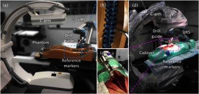
Phantom and cadaver studies. (a) Sawbones spine phantom experimental setup, (b) zoom-in of phantom region of interest, (c) zoom-in of cadaver region of interest, and (d) cadaver experimental setup. Tracker is not shown.
For each trajectory, the robotically held drill guide was placed close to the target plan, such that both the bony anatomy and the component were captured within the x-ray FoV. Following acquisition of radiographs and registration via KC-Reg, the robot was driven to the planned trajectory via KC guidance and a cone-beam CT (CBCT) scan was acquired at the target for offline error analysis. Returning to the same initial pose, the same steps were repeated for tracker guidance. For cadaver experiments, the lumbar spine was exposed, and six trajectories spanning L3–L5 were targeted. Note that while AP, lateral, and oblique radiographs were acquired for convenience, exact views are not required and a separation of 15 deg between each view was shown to be as accurate in prior studies.24 Trajectory planning and truth definition were as described above for the phantom study.
The accuracy of the system was quantified in terms of the target registration error (TRE) at the drill guide tip () and in aligning the principal component axis to target plan ()
| (10) |
where the last column () of the transformation matrix is the translation of the tooltip, and the third column (or last column of rotation matrix) defines the principal () axis of the component. The true poses of the patient and component were established by independent 3D–3D registrations of the CT volume () and component model () to the CBCT image reconstruction, respectively. The error windows in Figs. 7(c) and 8(c) show the screw placement range about the planned trajectory determined by the mean and of drill guide alignment. The window was offset by in any respective direction and rotationally swept by around the screw entry point.
Fig. 7.

Geometric accuracy of robotic guidance in the phantom study: (a) and (b) for KC and tracker guided approaches, (c) error windows (computed as described in Sec. 2.5) in L4 relative to the planned trajectory of a screw (green) based on mean errors for KC (cyan) and tracker (magenta) guidance. The planned screw entry point is marked with a dot.
Fig. 8.

Geometric accuracy of robotic positioning in the cadaver study: (a) and (b) for KC and tracker guided approaches, (c) error windows in L4 relative to the planned trajectory of a screw (green) based on mean errors for KC (cyan) and tracker (magenta) guidance. The planned screw entry point is marked with a dot.
3. Results
3.1. Assessment of Hand–Eye Calibration
Although hand–eye calibration is well established for robotic control using an optical tracker, performing it within the context of image-based guidance warrants additional study. Figure 5(a) summarizes evaluation of different solvers for the problem25–32 in terms of the distribution of the translational component of leave-one-out errors () computed as described in Sec. 2.2. The results suggest that separable solvers provided superior performance in this regard. Using the solver by Park et al., was observed to be [Fig. 5(b)]. A cross validation across repeat trials in Fig. 5(c) shows reduced variability in translational difference () between hand–eye calibrations for the KC approach () compared with the tracker () approach, highlighting the improved solution consistency for the former. A possible explanation for the improved consistency of the KC approach might be its ability to capture a larger variety of drill guide poses, cf. the passive markers that were visible only from the side that faces the tracker.
Fig. 5.

(a) Distribution of translational leave-one-out errors for solvers by (from left to right) Tsai, Horaud, Park, Chou, Andreff, Daniilidis, Shiu, and Wang et al.,25–32 (b) distribution of error () for the KC approach hand–eye calibration shown as a violin plot, where the shaded region is an estimation of the probability density function of underlying sample points, and (c) translational differences between hand–eye calibration trials for the tracker (upper left) and KC (lower right) approaches.
3.2. Phantom Study: Locality of the Solution
With the optical reference marker positioned on the phantom near L5 (also common in clinical practice), an increasing trend in TRE was expected for tracker guidance for trajectories farther from the reference marker (i.e., from L5). Figure Fig. 6(a) shows such degradation in the translational component of TRE for the tracker at increasing distances from the lumbar vertebrae. KC guidance is shown to be robust to such effects due to updated registration of the patient with new acquisitions.
Fig. 6.

(a) and (b) relative to the target vertebrae in spine phantom for two forms of guidance. The KC approach is observed to perform consistently across multiple vertebral levels in achieving both the target position and the approach angle. The shaded regions represent the 95% confidence interval about the regression lines.
In the spine phantom experiments, KC guidance yielded and , whereas tracker guidance resulted in and as seen in Figs. 7(a) and 7(b). Although the results were comparable overall, a paired -test suggests a statistically significant () error reduction in with KC guidance. A likely reason is the (intentional) spatial distribution of registration fiducials around the lumbar region (only), as such limited coverage is fairly common in normal practice. Still, both approaches offered acceptable error (theoretical placement within pedicle cortex) as shown in Fig. 7(c).
3.3. Cadaver Study: Robustness to Deformation
The cadaver underwent realistic gross anatomical deformation in handling and transport between the CT scanner and the C-arm/operating table—positioned prone in each case. KC guidance of the robot in the cadaver resulted in and as seen in Figs. 8(a) and 8(b), slightly higher than TRE in the phantom. Although the gradients produced by the deforming soft tissue and the reduced image quality due to higher attenuation (especially in the lateral view) presented challenges, the approach successfully maintained trajectories within the bony cortex as shown in Fig. 8(c). Despite care in transformation and placement of the specimen on the table, the induced deformation from the time of preoperative CT scan and the experiment resulted in significantly () higher errors when guiding with the tracker which presented of and . It is worth noting that the registration fiducials were also subject to the deformation between the preoperative CT and the time of experiment, compounding the error in tracker registration. In comparison, the KC approach remained robust to such changes, as it relies on structures that are relatively rigid, at least within the local region of the radiographic FoV (three to four vertebrae captured within a given radiographic view).
4. Conclusion
A method for robotic positioning of a pedicle drill guide via KC-Reg was presented, using fluoroscopic views already acquired within typical surgical workflow in combination with prior knowledge on patient anatomy (preoperative CT) and instrument shape (known-component model). Common practice in fluoroscopically guided orthopaedic or neuro-spine surgery involves multiplanar radiographic views that are qualitatively interpreted by the surgeon to assess 3D placement of surgical devices (e.g., to identify pedicle breach)—for example, PA and LAT views to assess position and depth in the pedicle, respectively. The KC approach accomplishes this from the same multiplanar views—or from views with as little as angular separation24—providing guidance and quality assurance that is accurate, quantitative, reproducible, and less subject to an individual surgeon’s expertise and qualitative image interpretation.
In phantom and cadaver experiments emulating pedicle screw placement, KC guidance of the robot was shown to perform comparably and, under conditions of gross anatomical deformation, better than tracker guidance. The implication is that KC guidance is less susceptible to the effects of anatomical deformation than conventional tracker-based guidance due to its use of local image features in the fluoroscopic FoV. However, a shortfall is recognized in the inability to account for patient movement between radiographic views; even with individual registrations per trajectory as in the experiments performed here, patient movement following registration is unaccounted when driving the robot. Furthermore, the time required for imaging and registration suggests a spot-check/step-and-shoot feedback in guidance rather than real-time guidance. For example, as in the current workflow of fluoroscopically guided procedures, the surgeon could acquire radiographic views at particular steps on each trans-pedicular path—e.g., just after entry, at midpoint, and/or at terminus of the trajectory. In contrast, optical trackers provide real-time feedback and account for rigid-body motion via an optical reference marker, but they are susceptible to anatomical deformation imparted over the course of surgery. The findings presented in this work, therefore, suggest the possibility of combining the KC guidance method with optical trackers to leverage the advantages of both.
One potential approach would use KC-Reg to update the tracker registration. This would require the tracked tool and KC to be in the same frame of reference, such that . Since the tracked tool calibration only accounts for the tooltip and the direction of cannula, the rotation about the cannula would be arbitrarily defined for tracker. A straightforward way to account for the missing degree of freedom could use the carefully obtained hand–eye calibrations, such that . The difference between the reported tool poses for the KC and tracker approaches can then be attributed to patient deformation and/or reference marker motion, such that , which describes the locally rigid offset between (used during tracker registration, prior to surgery) to current , expected to include deformation. The offset could be used to detect anatomical deformation and alert the surgeon that the tracker registration is outdated, and even applied to update it as , which can then be substituted into Eq. (9) to drive the robot as before.
KC guidance of robotic positioning appears promising, is consistent with fluoroscopic workflow, and could help reduce intraoperative radiation dose to the patient (fewer fluoroscopic views acquired in trial and error/qualitative interpretation) and to the surgical staff (with the robot end-effector—not the surgeon’s hands—in proximity to the radiographic FoV). A variety of areas for improvement in future work should be acknowledged. Differences between the physical and virtual models compound error during both the KC hand–eye calibration process and the KC-Reg computation of drill guide pose. A higher level of agreement could be achieved either through better modeling of the component—for example, using laser scanning or vendor-provided specifications—or by custom manufacturing using 3D printing. The hand–eye calibration solvers assessed in this work include a subset of the separable and simultaneous classes; however, iterative solvers could offer lower error.16 Advanced path planning approaches,33 collision detection,34 and virtual fixtures35 could be implemented to improve safety during robot motion. Finally, to further streamline workflow, the 3D–2D registration step runtime could be improved. The current implementation is such that the initial patient registration (CT-to-fluoroscopy) requires to 120 s to compute, addressing a broad search space and multistarts to ensure accurate registration of the anatomy.36 The subsequent KC registrations currently do not take advantage of this initialization, and require a similar to 180 s, including the additional component registration step. The workflow implications are that the initial registration is performed once (or infrequently) and that only KC registrations are required so often as to update the robot regarding potential shifts—e.g., once every other vertebral level. KC registration runtimes can, therefore, be improved by better utilization of this broad initialization, use of alternative (local) optimizers with faster convergence time,37 and utilization of more performant (or multiple) GPUs.
An alternative approach to the known-component registration used in this work is to outfit the effector with a dedicated radiopaque fiducial marker (also of known configuration) rigidly affixed to the surgical instrument.38,39 Such an approach may be advantageous in that the fiducial marker can be optimized for the task of 3D–2D registration, potentially increasing its conspicuity, the ability to localize in a single view, and the speed of registration. However, the KC approach offers several benefits by operating without additional markers and using the robot end-effector directly. First, it avoids the need for additional tools and requisite costs of disposal or sterilization. Second, it maintains the effector’s original intended design (e.g., that of a drill guide) and is accordingly compact and reduces risk of collision. Finally, the KC approach reduces the number of calibration steps to that of the hand–eye calibration of the robot to its end-effector, whereas a radiopaque fiducial approach would require an additional (fiducial-to-effector) tooltip calibration.
Although this study focused on robotic assistance in spine surgery, KC guidance can be envisioned for robotic positioning in other procedures as well. For example, the KC guidance of stereo EEG placement could benefit not only robotic positioning40 but also placement of the EEG leads themselves (as KCs). Similarly, the method could broaden the application of robotic assistance in procedures that currently rely heavily on fluoroscopic guidance and require a high degree of expertise on the part of the surgeon to place K-wire in complex anatomical shapes—e.g., pelvic trauma surgery.
Acknowledgments
The authors thank Drs. Sebastian Vogt, Gerhard Kleinszig, Markus Weiten, and Wei Wei (Siemens Healthineers) for valuable assistance regarding the mobile C-arm used in this work. The authors would also like to thank Mr. Ronn Wade (University of Maryland Anatomy Board) and Dr. Rajiv Iyer (Johns Hopkins Neurosurgery) for assistance with the cadaver specimen, Dr. Matthew Jacobson (Johns Hopkins Biomedical Engineering) for assistance with C-arm calibration and CT reconstruction, and Mr. Alex Martin (Johns Hopkins Biomedical Engineering) for design and fabrication of the drill guide robot attachment.
Biographies
Thomas Yi is a research assistant at the Johns Hopkins Medical Institutes. He received his BS degree in biomedical engineering and computer science from Johns Hopkins University in 2017. His research interests include image-guided surgery and surgical robotics.
Vignesh Ramchandran is a master’s student at Johns Hopkins University in applied mathematics and statistics. He received his BS degree in biomedical engineering from Johns Hopkins University in 2017. His research interests include machine learning, compressed sensing, and medical image analysis.
Jeffrey H. Siewerdsen received his PhD in physics from the University of Michigan in 1998. He is a professor of biomedical engineering, computer science, radiology, and neurosurgery and director of the Carnegie Center for Surgical Innovation at Johns Hopkins University. His research focuses on the physics of image quality in digital x-ray, CT, and cone-beam CT and the development of systems to improve precision, accuracy, and safety in image-guided interventions.
Ali Uneri received his PhD in computer science from Johns Hopkins University in 2017. He is a postdoctoral fellow at the Biomedical Engineering Department of Johns Hopkins University. His research focuses on image registration, 3D image reconstruction, and surgical robotics for image-guided interventions.
Disclosures
This research was supported by NIH Grant No. R01-EB-017226, NIH Training Grant No. 5 T32 AR067708-03, and academic–industry partnership with Siemens Healthineers (Erlangen Germany). No conflicts of interest, financial or otherwise, are declared by the authors.
References
- 1.Weiss A. J., et al. , Characteristics of Operating Room Procedures in U.S. Hospitals, 2011: HCUP Statistical Brief #170, Agency for Healthcare Research and Quality, Rockville, Maryland: (2014). [PubMed] [Google Scholar]
- 2.Perna F., et al. , “Pedicle screw insertion techniques: an update and review of the literature,” Musculoskeletal Surg. 100(3), 165–169 (2016). 10.1007/s12306-016-0438-8 [DOI] [PubMed] [Google Scholar]
- 3.Attar A., et al. , “Lumbar pedicle: surgical anatomic evaluation and relationships,” Eur. Spine J. 10(1), 10–15 (2001). 10.1007/s005860000198 [DOI] [PMC free article] [PubMed] [Google Scholar]
- 4.Gautschi O. P., et al. , “Clinically relevant complications related to pedicle screw placement in thoracolumbar surgery and their management: a literature review of 35, 630 pedicle screws,” Neurosurg. Focus 31(4), E8 (2011). 10.3171/2011.7.FOCUS11168 [DOI] [PubMed] [Google Scholar]
- 5.Amr A., Giese A., Kantelhardt S. R., “Navigation and robot-aided surgery in the spine: historical review and state of the art,” Rob. Surg. 2014(1), 19–26 (2014). 10.2147/RSRR.S54390 [DOI] [Google Scholar]
- 6.Roser F., Tatagiba M., Maier G., “Spinal robotics: current applications and future perspectives,” Neurosurgery 72(Suppl. 1), 12–18 (2013). 10.1227/NEU.0b013e318270d02c [DOI] [PubMed] [Google Scholar]
- 7.Kosmopoulos V., Schizas C., “Pedicle screw placement accuracy: a meta-analysis,” Spine 32(3), E111–E120 (2007). 10.1097/01.brs.0000254048.79024.8b [DOI] [PubMed] [Google Scholar]
- 8.Koivukangas T., Katisko J. P., Koivukangas J. P., “Technical accuracy of optical and the electromagnetic tracking systems,” SpringerPlus 2(1), 90 (2013). 10.1186/2193-1801-2-90 [DOI] [PMC free article] [PubMed] [Google Scholar]
- 9.Galloway R. L., Miga M. I., “Organ deformation and navigation,” in Imaging and Visualization in the Modern Operating Room: A Comprehensive Guide for Physicians, Fong Y., et al., Eds., pp. 121–132, Springer, New York: (2015). 10.1007/978-1-4939-2326-7_9 [DOI] [Google Scholar]
- 10.Taylor R. H., Stoianovici D., “Medical robotics in computer-integrated surgery,” IEEE Trans. Rob. Autom. 19(5), 765–781 (2003). 10.1109/TRA.2003.817058 [DOI] [Google Scholar]
- 11.Uneri A., et al. , “Known-component 3D–2D registration for quality assurance of spine surgery pedicle screw placement,” Phys. Med. Biol. 60(20), 8007–8024 (2015). 10.1088/0031-9155/60/20/8007 [DOI] [PMC free article] [PubMed] [Google Scholar]
- 12.Uneri A., et al. , “Intraoperative evaluation of device placement in spine surgery using known-component 3D–2D image registration,” Phys. Med. Biol. 62(8), 3330–3351 (2017). 10.1088/1361-6560/aa62c5 [DOI] [PMC free article] [PubMed] [Google Scholar]
- 13.De Silva T., et al. , “3D–2D image registration for target localization in spine surgery: investigation of similarity metrics providing robustness to content mismatch,” Phys. Med. Biol. 61(8), 3009–3025 (2016). 10.1088/0031-9155/61/8/3009 [DOI] [PMC free article] [PubMed] [Google Scholar]
- 14.Hansen N., Ostermeier A., “Completely derandomized self-adaptation in evolution strategies,” Evol. Comput. 9(2), 159–195 (2001). 10.1162/106365601750190398 [DOI] [PubMed] [Google Scholar]
- 15.Penney G. P., et al. , “A comparison of similarity measures for use in 2-D–3-D medical image registration,” IEEE Trans. Med. Imaging 17(4), 586–595 (1998). 10.1109/42.730403 [DOI] [PubMed] [Google Scholar]
- 16.Shah M., et al. , “An overview of robot-sensor calibration methods for evaluation of perception systems,” in Proc. Workshop Performance Metrics for Intelligent Systems (PERMIS 2012), p. 15 (2012). 10.1145/2393091.2393095 [DOI] [Google Scholar]
- 17.Uneri A., et al. , “TREK: an integrated system architecture for intraoperative cone-beam CT-guided surgery,” Int. J. Comput. Assist. Radiol. Surg. 7(1), 159–173 (2012). 10.1007/s11548-011-0636-7 [DOI] [PMC free article] [PubMed] [Google Scholar]
- 18.Goerres J., et al. , “Spinal pedicle screw planning using deformable atlas registration,” Phys. Med. Biol. 62(7), 2871–2891 (2017). 10.1088/1361-6560/aa5f42 [DOI] [PMC free article] [PubMed] [Google Scholar]
- 19.Wicker R., Tedla B., “Automatic determination of pedicle screw size, length, and trajectory from patient data,” in Conf. Proc. IEEE Engineering in Medicine and Biology Society, Vol. 2, pp. 1487–1490 (2004). 10.1109/IEMBS.2004.1403457 [DOI] [PubMed] [Google Scholar]
- 20.Lee J., et al. , “Optimal surgical planning guidance for lumbar spinal fusion considering operational safety and vertebra-screw interface strength,” Int. J. Med. Robot. Comput. Assist. Surg. 8(3), 261–272 (2012). 10.1002/rcs.1413 [DOI] [PubMed] [Google Scholar]
- 21.Daemi N., et al. , “Planning screw insertion trajectory in lumbar spinal fusion using pre-operative CT images,” in Proc. of the Annual Int. Conf. of the IEEE Engineering in Medicine and Biology Society (EMBS 2015), pp. 3639–3642 (2015). 10.1109/EMBC.2015.7319181 [DOI] [PubMed] [Google Scholar]
- 22.Knez D., et al. , “Computer-assisted screw size and insertion trajectory planning for pedicle screw placement surgery,” IEEE Trans. Med. Imaging 35(6), 1420–1430 (2016). 10.1109/TMI.2016.2514530 [DOI] [PubMed] [Google Scholar]
- 23.Solitro G. F., Amirouche F., “Innovative approach in the development of computer assisted algorithm for spine pedicle screw placement,” Med. Eng. Phys. 38(4), 354–365 (2016). 10.1016/j.medengphy.2016.01.005 [DOI] [PubMed] [Google Scholar]
- 24.Uneri A., et al. , “3D–2D registration for surgical guidance: effect of projection view angles on registration accuracy,” Phys. Med. Biol. 59(2), 271–287 (2014). 10.1088/0031-9155/59/2/271 [DOI] [PMC free article] [PubMed] [Google Scholar]
- 25.Tsai R. Y., Lenz R. K., “A new technique for fully autonomous and efficient 3D robotics hand/eye calibration,” IEEE Trans. Rob. Autom. 5(3), 345–358 (1989). 10.1109/70.34770 [DOI] [Google Scholar]
- 26.Horaud R., Dornaika F., “Hand-eye calibration,” Int. J. Rob. Res. 14(3), 195–210 (1995). 10.1177/027836499501400301 [DOI] [Google Scholar]
- 27.Park F. C., Martin B. J., “Robot sensor calibration: solving AX = XB on the Euclidean group,” IEEE Trans. Rob. Autom. 10(5), 717–721 (1994). 10.1109/70.326576 [DOI] [Google Scholar]
- 28.Chou J. C. K., Kamel M., “Finding the position and orientation of a sensor on a robot manipulator using quaternions,” Int. J. Rob. Res. 10(3), 240–254 (1991). 10.1177/027836499101000305 [DOI] [Google Scholar]
- 29.Andreff N., Horaud R., Espiau B., “On-line hand-eye calibration,” in Second Int. Conf. on 3-D Digital Imaging and Modeling (Cat. No. PR00062), pp. 430–436 (1999). 10.1109/IM.1999.805374 [DOI] [Google Scholar]
- 30.Daniilidis K., “Hand-eye calibration using dual quaternions,” Int. J. Rob. Res. 18(3), 286–298 (1999). 10.1177/02783649922066213 [DOI] [Google Scholar]
- 31.Shiu Y. C., Ahmad S., “Calibration of wrist-mounted robotic sensors by solving homogeneous transform equations of the form AX = XB,” IEEE Trans. Rob. Autom. 5(1), 16–29 (1989). 10.1109/70.88014 [DOI] [Google Scholar]
- 32.Wang C. C., “Extrinsic calibration of a vision sensor mounted on a robot,” IEEE Trans. Rob. Autom. 8(2), 161–175 (1992). 10.1109/70.134271 [DOI] [Google Scholar]
- 33.Sariff N., Buniyamin N., “An overview of autonomous mobile robot path planning algorithms,” in 4th Student Conf. on Research and Development (SCOReD 2006), pp. 183–188 (2006). 10.1109/SCORED.2006.4339335 [DOI] [Google Scholar]
- 34.Reggiani M., Mazzoli M., Caselli S., “An experimental evaluation of collision detection packages for robot motion planning,” Int. Conf. Intell. Rob. Syst. 3, 2329–2334 (2002). 10.1109/IRDS.2002.1041615 [DOI] [Google Scholar]
- 35.Li M., Kapoor A., Taylor R. H., “A constrained optimization approach to virtual fixtures,” in IEEE/RSJ Int. Conf. Intelligent and Robotic Systems, pp. 1408–1413 (2005). 10.1109/IROS.2005.1545420 [DOI] [Google Scholar]
- 36.Otake Y., et al. , “Robust 3D–2D image registration: application to spine interventions and vertebral labeling in the presence of anatomical deformation,” Phys. Med. Biol. 58(23), 8535–8553 (2013). 10.1088/0031-9155/58/23/8535 [DOI] [PMC free article] [PubMed] [Google Scholar]
- 37.Powell M. J. D., “An efficient method for finding the minimum of a function of several variables without calculating derivatives,” Comput. J. 7(2), 155–162 (1964). 10.1093/comjnl/7.2.155 [DOI] [Google Scholar]
- 38.Dang H., et al. , “Robust methods for automatic image-to-world registration in cone-beam CT interventional guidance,” Med. Phys. 39(10), 6484–6498 (2012). 10.1118/1.4754589 [DOI] [PMC free article] [PubMed] [Google Scholar]
- 39.Shoham M., et al. , “Robotic assisted spinal surgery—from concept to clinical practice,” Comput. Aided Surg. 12(2), 105–115 (2007). 10.3109/10929080701243981 [DOI] [PubMed] [Google Scholar]
- 40.Brandmeir N. J., et al. , “The comparative accuracy of the ROSA stereotactic robot across a wide range of clinical applications and registration techniques,” J. Rob. Surg. 1–7 (2017). 10.1007/s11701-017-0712-2 [DOI] [PubMed] [Google Scholar]