Abstract
This paper investigates the finite-time synchronization and fixed-time synchronization problems of inertial memristive neural networks with time-varying delays. By utilizing the Filippov discontinuous theory and Lyapunov stability theory, several sufficient conditions are derived to ensure finite-time synchronization of inertial memristive neural networks. Then, for the purpose of making the setting time independent of initial condition, we consider the fixed-time synchronization. A novel criterion guaranteeing the fixed-time synchronization of inertial memristive neural networks is derived. Finally, three examples are provided to demonstrate the effectiveness of our main results.
Keywords: Inertial memristive neural networks, Time-varying delay, Feedback control, Finite-time synchronization, Fixed-time synchronization
Introduction
The memristor was originally predicted by Chua (1971), which is considered to be the fourth basic circuit element besides resistor, capacitor and inductor. However, the first practical memristor device was realized by HP laboratory until 2008 (Strukov et al. 2008). Similar to the operating principle of synapsis in human brain, the memristor has the function of memorizing the direction of flow of electric charge in the past. Therefore, it performs as a forgetting and remembering process in human brains. In recent years, memristor has become a hot topic due to its potential applications in next generation computers and powerful brain-like computers. By substituting resistor in traditional neural network with memristor, the memristive neural network is then constructed, which can make the artificial neural networks of human brain better. Recently, there have been many interesting research on the dynamics of memristive neural networks (Li and Cao 2016; Yang et al. 2017; Qi et al. 2014; Rakkiyappan et al. 2015; Chen et al. 2015). In Qi et al. (2014), the stability of delayed memristive neural networks with time-varying impulses is studied. The stability of memristor-based fractional-order neural networks with different memductance functions is investigated using Lyapunov method and Banach contraction principle in Rakkiyappan et al. (2015).
The second-order term in neural network is called inertial term, which cause more complex dynamic behavior compared with first-order neural networks. Physically, the second-order term represents inductance in circuit systems. There is strong biological background for the introduction of an inductance term in neural system (Ke and Miao 2013; Liu et al. 2009; Zhang and Quan 2015; Dong et al. 2012; He et al. 2012; Li et al. 2004; Liu et al. 2009; Wheeler and Schieve 1997; Hu et al. 2015; Zhang et al. 2015; Cao and Wan 2014). In semicircular canals of some animals, the membrane of a hair cell can be implemented by equivalent circuits that contain an inductance (Liu et al. 2009; Zhang and Quan 2015; Dong et al. 2012). The squid axon of sepia can also be elaborated by designing an inductance (He et al. 2012; Li et al. 2004; Liu et al. 2009; Wheeler and Schieve 1997). Hu et al. (2015) investigates the synchronization for an array of linearly and diffusively coupled inertial delayed neural networks (DNNs) by pinning control. The stability and synchronization of inertial neural network with time-delays is studied using matrix measure strategy in Cao and Wan (2014). Up to now, most of the results of inertial network have not taken the impact of memristors into consideration.
By combining inertial neural network and memristive neural network, inertial memristive neural network is then constructed. Until now, there are still very few results about this type of neural network (Rakkiyappan et al. 2016), which motivates our study. Due to the physical meaning and biological background of inertial and memristor, the combination of them can model more complex dynamical behavior in nature and extend the theorem of neural networks.
Synchronization is an important phenomenon in nature, and has been widely applied in various fields such as chemical reactors, biological systems, information processing, secure communication, etc. (Cao and Lu 2006; Ke and Miao 2013; Yang et al. 2015; Rakkiyappan et al. 2016; Balasubramaniam et al. 2011; Wang et al. 2014; Wen et al. 2013; Wu and Zeng 2015; Yang et al. 2014; Wan et al. 2016; Abdurahman et al. 2015; Liu et al. 2016). In Yang et al. (2015), exponential synchronization of neural networks with discontinuous activations with mixed delays has been discussed by combining state feedback control and impulsive control techniques. Rakkiyappan et al. (2016) has discussed the global exponential stability of inertial memristive neural networks and global exponential pinning synchronization of coupled inertial memristive neural networks. Exponential synchronization of memristive Cohen-Grossberg neural networks with mixed delays is researched in Yang et al. (2014). It is noticed that, most results about synchronization are limited to an infinite-time asymptotical process (Cao and Lu 2006; Ke and Miao 2013; Yang et al. 2015; Rakkiyappan et al. 2016; Balasubramaniam et al. 2011; Wang et al. 2014; Wen et al. 2013; Wu and Zeng 2015; Yang et al. 2014), that is, only when the time tends to infinity, the error between drive-response systems approaches zero. But in practical fields such as physical and engineering systems, due to the machine’s and human’s life spans are limited, we often require systems to achieve synchronization in finite time (Wan et al. 2016; Abdurahman et al. 2015; Liu et al. 2016; Polyakov 2012; Liu et al. 2014; Shen and Cao 2011; Bao and Cao 2016; Bhat and Bernstein 2000). Shen and Cao (2011) has investigated finite-time synchronization of an array of coupled neural networks via discontinuous controllers. In Bao and Cao (2016), the author has studied the finite-time generalized synchronization of nonidentical delayed chaotic systems. Up to now, the research for the finite-time synchronization of inertial memristive neural networks has not been found yet.
Different from the finite-time synchronization, where the final convergence time is closely related to the initial synchronization errors, the settling time of the fixed-time synchronization can be directly calculated regardless of the initial synchronization errors, which can lead to better applications in real practices (Wan et al. 2016; Polyakov 2012). To the best of the authors knowledge, the fixed-time synchronization of inertial memristive neural networks has not been studied in previous paper yet, this motivates our current research interest.
The main contribution of this paper is that it provides effective controllers to realize finite-time and fixed-time synchronization for inertial memristive neural networks.
The remainder of this paper is organized as follows. In section “Preliminaries”, some notations and preliminaries are given. The model formulation and main results are presented in sections “Modeling” and “Main results”. In section “Numerical examples”, three numerical examples are given to demonstrate the effectiveness of the main results. Finally, conclusions are drawn in section “Conclusion”.
Notations. Throughout this paper, denotes the n-dimensional Euclidean space. The superscript T denotes vector transposition. is the set of all real matrices. is the identity matrix of order n. is the sign function. denotes the family of continuous functions from to .
Preliminaries
In this section, some elementary notations and lemmas are introduced which play an important role in the proof of the main results in section “Modeling”.
Definition 1
(Filippov and Arscott 2013) Suppose , then is called a set-valued map from , if for each point , there exists a nonempty set . A set-valued map F with nonempty values is said to be upper semicontinuous at , if for any open set N containing , there exists a neighbourhood M of such that . The map F(x) is said to have a closed image if for each , F(x) is closed.
Definition 2
(Filippov and Arscott 2013) For the system , , with discontinuous right-hand sides, a set-valued map is defined as
where is the closure of the convex hull of set E, , and is the Lebesgue measure of set N. A solution in Filippov’s sense of the Cauchy problem for this system with initial condition is an absolutely continuous function x(t), , which satisfies the differential inclusion
Lemma 1
(Shen and Cao 2011) Assume that a continuous, positive-definite function V(t) satisfies the following differential inequality:
where . Then, V(t) satisfies the following inequality:
and for all with given by .
Lemma 2
(Polyakov 2012) Assume that a continuous radically unbounded function satisfies the following differential inequality
- (1)
- (2)
for some , where is the set-valued Lie derivative of V.
Then, , with the settling time bounded by .
Lemma 3
(Xu and Wang 1983) If , , then
Lemma 4
(Xu and Wang 1983) For any real vectors , the following inequality holds
Modeling
Consider the dynamic equation of the ith node of the inertial memristive neural network consisting of n nodes:
| 1 |
where is the state vector of the ith neuron. , are positive constants. The second derivative of is called an inertial term of system (1). The nonlinear function denotes activation function for the neural network. is the external input of the system. is the time-varying delay that satisfies , , where , are constants. and are the memristive connection weights. According to the character of the memristor, the state parameters in (1) are supposed to satisfy the following condition:
| 2 |
| 3 |
for , where are known constants with respect to memristors. The initial value associated with system (1) is
where , .
To derive the main results, the following assumptions are introduced.
Assumption 1
For all ,, the neural activation function satisfies
where are known constants.
Assumption 2
There exists constants s.t..
Based on the theories of set-valued maps and differential inclusions, the model (1) with initial values can be described by the following differential inclusion:
| 4 |
where ,
| 5 |
or equivalently, for , there exists , such that
| 6 |
Next, by introducing the following variable transformation:
system (6) can be transformed into the first-order form
| 7 |
with the initial condition given by
| 8 |
where .
By letting , system (7) can be written as the following compact form:
| 9 |
where , .
Now we choose (9) as the master system, the corresponding slave system is formulated as
| 10 |
where are the state variables of the response system, are control inputs to be designed later. .
Denote the synchronization error , we get the error system
| 11 |
Design the following state feedback controller
| 12 |
where are the tunable parameters, are the parameters that remain to be designed.
Definition 3
(Shen and Cao 2011) If there exists a constant which depends on the initial vector value that satisfies
.
Then the drive-response system (9) and (10) is said to achieve finite-time synchronization with settling time .
For the convenience of the following discussion, we introduce some notations as follows,
Main results
Finite-time synchronization
Theorem 1
Under Assumption 1 and 2 , the drive-response systems (9) and (10) will achieve finite-time synchronization under controller (12) if the following conditions hold
for , and the setting time is given by .
Proof
Choose a Lyapunov functional as
Taking the set-valued Lie derivative of V(t) with respect to t along the trajectory of the error system (11) yields
| 13 |
According to Assumptions 1 and 2, it follows that
| 14 |
Similarly, we have
| 15 |
Thus,
| 16 |
Substituting (14), (15) and (16) into (13), it follows that
| 17 |
When the parameters satisfy the following condition
we have According to Lemma 1, , where . That is, . By Definition 3, drive-response system (9) and (10) will realize finite-time synchronization in a finite time .
Remark 1
By designing the state feedback controller which contain both the current and past state information, the finite-time synchronization of drive-response system can be achieved. It can be seen that the sign function plays an important role in this controller designing. Note that the settling time can be turned by selecting different values of c and . Compared with Hu et al. (2015) and Cao and Wan (2014), the impact of memristor is taken into account in the dynamics of inertial neural network. Due to the memory characteristic of memristor , it has better performance in imitating the biological synapses. The network model considered here has characteristics of complex brain networks such as node degree, distribution, so it may provide a helpful tool in research for cognitive neural dynamics.
According to the character of the memristor, each of matrices has possible values. Then, choose the largest eigenvalue of the cases and give the following notations
When the feedback controller are chosen as follows
| 18 |
where , , . Then, we have the following theorem.
Theorem 2
Under Assumption 1 and 2 , the drive-response systems (9) and (10) will achieve finite-time synchronization when the following conditions hold
for , and the setting time is given by .
Proof
Choose a Lyapunov functional as
where are the constants to be determined later.
Taking the set-valued Lie derivative of V(t) with respect to t along the trajectory of the error system (11) and utilizing Lemma 4 yields
| 19 |
Choose , then Substituting into (19), it can be achieved that
| 20 |
Therefore,
| 21 |
When the parameters satisfy the conditions
we have
According to Lemma 3, we have
| 22 |
By Lemma 1, it follows that . Due to , thus, . According to Definition 3, drive-response system (9) and (10) will realize finite-time synchronization with the settling time .
Remark 2
Compared with Rakkiyappan et al. (2016), where the global exponential stability of inertial memristive neural networks and global exponential pinning synchronization of coupled inertial memristive neural networks are discussed, we consider the finite-time synchronization of the same network model here. Different from previous work which focus on the asymptotic synchronization, we care more about the length of convergence time and design a controller to make it be able to adjusted to an arbitrary length. It has been proved that finite-time synchronization has better application in the practical fields, such as signal processing, pattern recognition, associative memories and optimization problems. Thus, our work is the extension of Rakkiyappan et al. (2016).
Fixed-time synchronization
According to the previous discussion, the settling time of finite-time synchronization relies on the initial condition of drive-response systems. Thus, different initial conditions may result in different convergence time. However, the initial condition of many practical systems can hardly be estimated or even impossible to be measured, which leads to the inaccessibility of the final settling time and deteriorating of the systems performance. To overcome this difficulty, the concept of fixed-time synchronization is proposed, where the settling time is independent of the initial conditions.
Consider the drive-response model (9) and (10) mentioned above. Choose the following fixed-time controller
| 23 |
then the error system is obtained as follows
| 24 |
where are tunable constants, are the parameters to be determined later.
Definition 4
If the drive-response systems (9) and (10) satisfy the condition of finite-time synchronization, furthermore, there exists constant such that
Then, the drive-response systems (9) and (10) are said to achieve fixed-time synchronization.
Theorem 3
The drive-response systems (9) and (10) will achieve fixed-time synchronization if the following conditions hold
That is,
Proof
Choose a Lyapunov functional as
Taking the set-valued Lie derivative of V(t) with respect to t along the trajectory of the error system (21) yields
| 25 |
According to Assumptions 1 and 2, we have
| 26 |
By Lemma 3, it follows that
| 27 |
Substituting (26) and (27) into , we have
| 28 |
When the parameters satisfy the condition in Theorem 3
we have . From Lemma 2, V(t) converges to zero in a fixed time, and the fixed time is estimated by . Hence, . Consequently, under controller (23), systems (9) and (10) realize fixed-time synchronization. This completes the proof of the theorem.
Remark 3
Compared with finite-time synchronization where the convergence time relies on the initial synchronization error, the settling time of fixed-time synchronization is independent on initial conditions. In some fields, such as secure communication and pattern recognition, it has restrictive requirement on the convergence speed and the initial conditions are usually hard to be obtained. Thus, the fixed-time synchronization is more favorable and applicable than finite-time synchronization in such cases.
Numerical examples
In this section, numerical examples are presented to illustrate the effectiveness of our results.
Example 1
Consider the following inertial memristive neural network with the master system given by
| 29 |
where
| 30 |
and the slave system described as
| 31 |
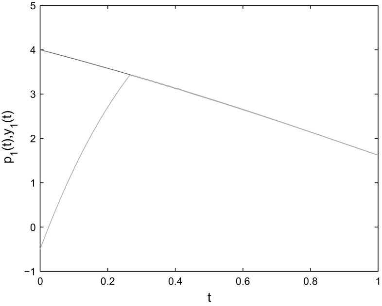
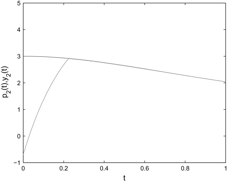
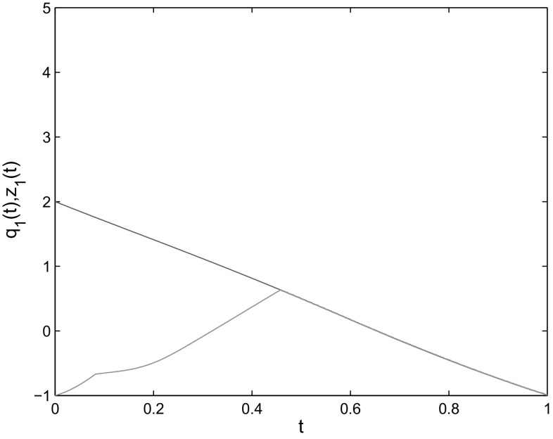
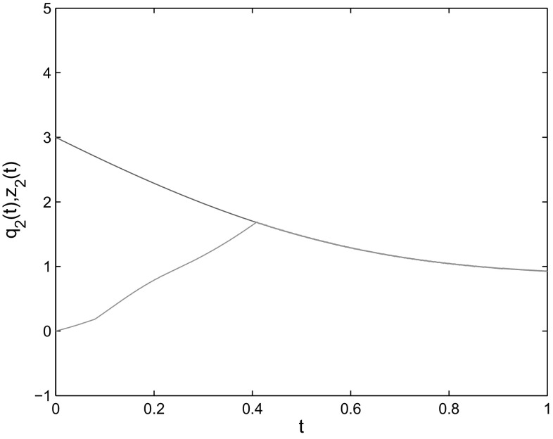
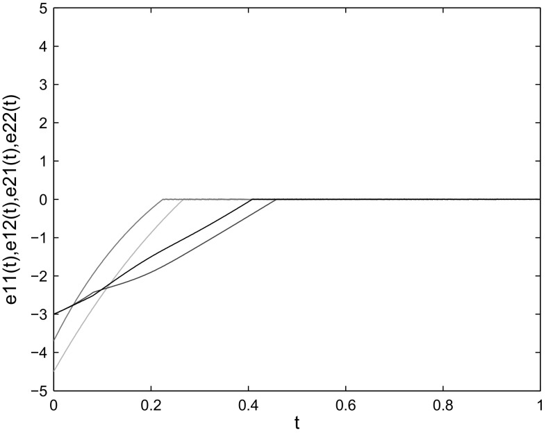
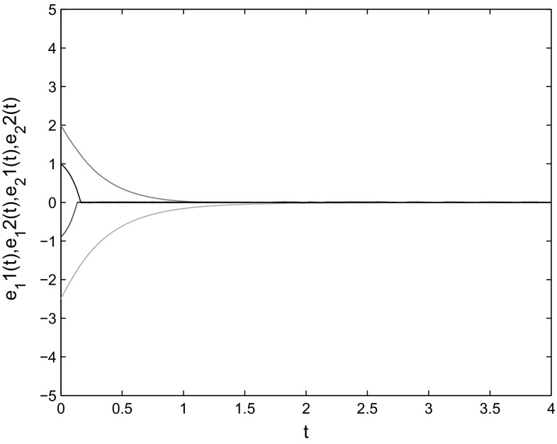
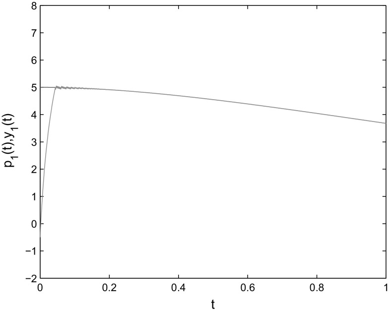
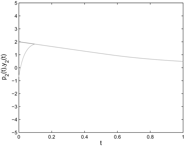
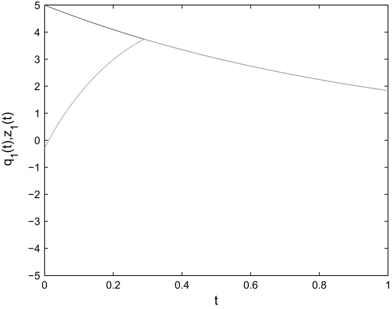
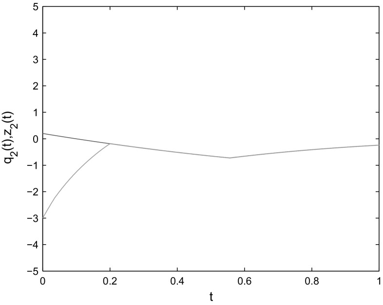
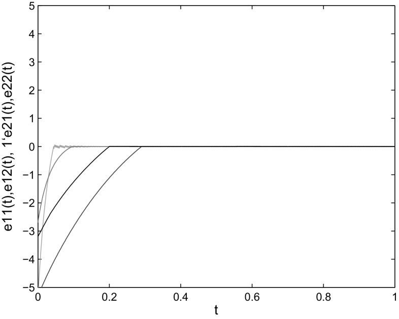
where , , , . By Assumptions 1 and 2, , When the control gains are taken as , the condition of Theorem 1 is satisfied. The initial conditions are chosen as One can see from Figs. 1, 2, 3, 4 and 5 that the states of the slave system indeed converge to the master system with the settling time and the convergence error remains zero afterwards. Thus, the effectiveness of Theorem 1 is verified.
Fig. 1.
State trajectories of and
Fig. 2.
State trajectories of and
Fig. 3.
State trajectories of and
Fig. 4.
State trajectories of and
Fig. 5.
Example 2
Consider the following inertial memristive neural network with the master system given by
| 32 |
where
| 33 |
and the slave system is
| 34 |
where By Assumptions 1 and 2, ,, When the control gains are taken as the condition of Theorem 2 is satisfied. Choose the initial condition as The simulation results are shown as Fig. 6, which verify the effectiveness of Theorem 2.
Fig. 6.
Example 3
Consider the following master inertial memristive neural network
| 35 |
where
| 36 |
and the slave system is
| 37 |
where , , , . According to Assumption 1 and 2, . When the control gains are chosen as , the condition of Theorem 3 is satisfied. The initial condition is taken as The simulation results are shown as Figs. 7, 8, 9, 10 and 11, which verify the effectiveness of Theorem 3.
Fig. 7.
State trajectories of and
Fig. 8.
State trajectories of and
Fig. 9.
State trajectories of and
Fig. 10.
State trajectories of and
Fig. 11.
Conclusion
This paper has addressed the finite-time and fixed-time master-slave synchronization control problem for the inertial memristive neural networks with time-varying delays. Utilizing the Fillipov discontinuous theory and a variable transformation, the problem of second-order equations can be converted into first-order one. Then, by designing Lyapunov function and constructing feedback controller, sufficient conditions are derived respectively for the two types of synchronization. Finally, numerical simulations have been presented to verify the effectiveness of our theoretical results.
Acknowledgements
This work was supported by the National Natural Science Foundation of China under Grant Nos. 61573096 and 61272530.
Contributor Information
Ruoyu Wei, Email: 220141289@seu.edu.cn, Email: 2957543746@qq.com.
Jinde Cao, Email: jdcao@seu.edu.cn.
Ahmed Alsaedi, Email: aalsaedi@hotmail.com.
References
- Abdurahman A, Jiang H, Teng Z. Finite-time synchronizing for memrisor-based neural networks with time-varying delays. Neural Netw. 2015;69:20–28. doi: 10.1016/j.neunet.2015.04.015. [DOI] [PubMed] [Google Scholar]
- Balasubramaniam P, Chandran R, Jeeva S. Synchronization of chaotic nonlinear continuous neural networks with time-varying delay. Cogn Neurodyn. 2011;5:361–371. doi: 10.1007/s11571-011-9162-0. [DOI] [PMC free article] [PubMed] [Google Scholar]
- Bao H, Cao J. Finite-time generalized synchronization of nonidentical delayed chaotic systems. Nonlinear Anal: Model Control. 2016;21(3):306–324. [Google Scholar]
- Bhat S, Bernstein D. Finite-time stability of continuous autonomous systems. SIAM J Control Optim. 2000;38(3):751–766. doi: 10.1137/S0363012997321358. [DOI] [Google Scholar]
- Cao J, Lu J. Adaptive synchronization of neural networks with or without time-varying delays. Chaos. 2006;16(1):013133. doi: 10.1063/1.2178448. [DOI] [PubMed] [Google Scholar]
- Cao J, Wan Y. Matrix measure strategies for stability and synchronization of inertial neural network with time-delays. Neural Netw. 2014;53:165–172. doi: 10.1016/j.neunet.2014.02.003. [DOI] [PubMed] [Google Scholar]
- Chen L, Wu R, Cao J, Liu J. Stability and synchronization of memristor-based fractional-order delayed neural networks. Neural Netw. 2015;71:37–44. doi: 10.1016/j.neunet.2015.07.012. [DOI] [PubMed] [Google Scholar]
- Chua LO. Memristor-the missing circuit element. IEEE Trans Circuit Theory. 1971;18:507–519. doi: 10.1109/TCT.1971.1083337. [DOI] [Google Scholar]
- Dong T, Liao X, Huang T. Hopf-pitchfork bifurcation in an inertial two-neuron system with time delay. Neurocomputing. 2012;97:223–232. doi: 10.1016/j.neucom.2012.06.008. [DOI] [Google Scholar]
- Filippov AF, Arscott FM. Differential equations with discontinuous right hand sides: control systems. Berlin: Springer; 2013. [Google Scholar]
- He X, Li C, Shu Y. Bogdanov–Takens bifurcation in a single inertial neural model with delay. Neurocomputing. 2012;89:193–201. doi: 10.1016/j.neucom.2012.02.019. [DOI] [Google Scholar]
- Hu J, Cao J, Alofi A, Abdullah A, Elaiw A. Pinning synchronization of coupled inertial delayed neural networks. Cogn Neurodyn. 2015;9:341–350. doi: 10.1007/s11571-014-9322-0. [DOI] [PMC free article] [PubMed] [Google Scholar]
- Ke Y, Miao C. Stability analysis of inertial Cohen–Grossberg-type neural networks with time delays. Neurocomputing. 2013;117:196–205. doi: 10.1016/j.neucom.2013.01.026. [DOI] [Google Scholar]
- Ke Y, Miao C. Stability and existence of periodic solutions in inertial BAM neural networks with time delay. Neural Comput Appl. 2013;23(3):1089–1099. [Google Scholar]
- Li N, Cao J. Lag synchronization of memristor-based coupled neural networks via -measure. IEEE Trans Neural Netw Learn Syst. 2016;27(3):169–182. doi: 10.1109/TNSRE.2015.2466079. [DOI] [PubMed] [Google Scholar]
- Li C, Chen G, Yu J. Hopf bifurcation and chaos in a single inertial neuron model with time delay. Eur Phys J B. 2004;41:337–343. doi: 10.1140/epjb/e2004-00327-2. [DOI] [Google Scholar]
- Liu Q, Liao X, Guo S, Wu Y. Stability of bifurcating periodic solution for a single delayed inertial neuron model under periodic excitation. Nonlinear Anal: Real World Appl. 2009;10:2384–2395. doi: 10.1016/j.nonrwa.2008.04.025. [DOI] [Google Scholar]
- Liu Q, Liao X, Liu Y. Dynamics of an inertial two-neuron system with time delay. Nonlinear Dyn. 2009;58(3):573–609. doi: 10.1007/s11071-009-9503-2. [DOI] [Google Scholar]
- Liu X, Ho DWC, Yu W, Cao J. A new switching design to finite-time stabilization of nonlinear systems with applications to neural networks. Neural Netw. 2014;57:94–102. doi: 10.1016/j.neunet.2014.05.025. [DOI] [PubMed] [Google Scholar]
- Liu X, Su H, Chen M. A switching approach to designing finite-time synchronization controllers of coupled neural networks. IEEE Trans Neural Netw Learn Syst. 2016;27(2):471–482. doi: 10.1109/TNNLS.2015.2448549. [DOI] [PubMed] [Google Scholar]
- Polyakov A. Nonlinear feedback design for fixed-time stabilization of linear control systems. IEEE Trans Autom Control. 2012;57(8):2106–2110. doi: 10.1109/TAC.2011.2179869. [DOI] [Google Scholar]
- Qi J, Li C, Huang T. Stability of delayed memristive neural networks with time-varying impulses. Cogn Neurodyn. 2014;8:429–436. doi: 10.1007/s11571-014-9286-0. [DOI] [PMC free article] [PubMed] [Google Scholar]
- Rakkiyappan R, Velmurugan G, Cao J. Stability analysis of memristor-based fractional-order neural networks with different memductance functions. Cogn Neurodyn. 2015;9:145–177. doi: 10.1007/s11571-014-9312-2. [DOI] [PMC free article] [PubMed] [Google Scholar]
- Rakkiyappan R, Premalatha S, Chandrasekar A, Cao J. Stability and synchronization of innertial memristive neural networks with time delays. Cogn Neurodyn. 2016;10:437–451. doi: 10.1007/s11571-016-9392-2. [DOI] [PMC free article] [PubMed] [Google Scholar]
- Shen J, Cao J. Finite-time synchronization of coupled neural networks via discontinuous controllers. Cogn Neurodyn. 2011;5(4):372–385. doi: 10.1007/s11571-011-9163-z. [DOI] [PMC free article] [PubMed] [Google Scholar]
- Strukov D, Snider G, Stewart D, Williams RS. The missing memristor found. Nature. 2008;453:80–83. doi: 10.1038/nature06932. [DOI] [PubMed] [Google Scholar]
- Wan Y, Cao J, Wen G, Yu W. Robust fixed-time synchronization of delayed Cohen–Grossburg neural networks. Neural Netw. 2016;73:86–94. doi: 10.1016/j.neunet.2015.10.009. [DOI] [PubMed] [Google Scholar]
- Wang W, Li L, Peng H, Xiao J, Yang Y. Synchronization control of memristor-based recurrent neural networks with perturbations. Neural Netw. 2014;53:8–14. doi: 10.1016/j.neunet.2014.01.010. [DOI] [PubMed] [Google Scholar]
- Wen S, Bao G, Zeng Z, Chen Y, Huang T. Global exponential synchronization of memristor-based recurrent neural networks with time-varying delays. Neural Netw. 2013;48:195–203. doi: 10.1016/j.neunet.2013.10.001. [DOI] [PubMed] [Google Scholar]
- Wheeler WD, Schieve WC. Stability and chaos in an inertial two-neuron system. Phys B. 1997;105:267–284. [Google Scholar]
- Wu A, Zeng Z. Global Mittag–Leffler stabilization of fractional-order memristive neural networks. IEEE Trans Neural Netw Learn Syst. 2015;3:1–12. doi: 10.1109/TNNLS.2015.2506738. [DOI] [PubMed] [Google Scholar]
- Xu L, Wang X. Mathematical analysis method and examples. Beijing: Higher Education Press; 1983. [Google Scholar]
- Yang X, Cao J, Yu W. Exponential synchronization of memristive Cohen–Grossberg neural networks with mixed delays. Cogn Neurodyn. 2014;8:239–249. doi: 10.1007/s11571-013-9277-6. [DOI] [PMC free article] [PubMed] [Google Scholar]
- Yang X, Cao J, Ho DWC. Exponential synchronization of discontinuous neural networks with time-varying mixed delay via state feedback and impulsive control. Cogn Neurodyn. 2015;9:113–128. doi: 10.1007/s11571-014-9307-z. [DOI] [PMC free article] [PubMed] [Google Scholar]
- Yang X, Cao J, Liang J. Exponential Synchronization of memeristive neural networks with delays:Interval matrix method. IEEE Trans Neural Netw Learn Syst. 2015;28(8):1878–1888. doi: 10.1109/TNNLS.2016.2561298. [DOI] [PubMed] [Google Scholar]
- Zhang Z, Quan Z. Global exponential stability via inequality technique for inertial BAM neural networks with time delays. Neurocomputing. 2015;151(3):1316–1326. doi: 10.1016/j.neucom.2014.10.072. [DOI] [Google Scholar]
- Zhang W, Li C, Huang T, Tan J. Exponential stability of inertial BAM neural networks with time-varying delay via periodically intermittent control. Neural Comput Appl. 2015;26:1781–1787. doi: 10.1007/s00521-015-1838-7. [DOI] [Google Scholar]


