Abstract
Objective: To investigate the stress distribution to the mandible, with and without impacted third molars (IM3s) at various orientations, resulting from a 2000-Newton impact force either from the anterior midline or from the body of the mandible. Materials and methods: A 3D mandibular virtual model from a healthy dentate patient was created and the mechanical properties of the mandible were categorized to 9 levels based on the Hounsfield unit measured from computed tomography (CT) images. Von Mises stress distributions to the mandibular angle and condylar areas from static impact forces (Load I-front blow and Load II left blow) were evaluated using finite element analysis (FEA). Six groups with IM3 were included: full horizontal bony, full vertical bony, full 450 mesioangular bony, partial horizontal bony, partial vertical, and partial 450 mesioangular bony impaction, and a baseline group with no third molars. Results: Von Mises stresses in the condyle and angle areas were higher for partially than for fully impacted third molars under both loading conditions, with partial horizontal IM3 showing the highest fracture risk. Stresses were higher on the contralateral than on the ipsilateral side. Under Load II, the angle area had the highest stress for various orientations of IM3s. The condylar region had the highest stress when IM3s were absent. Conclusions: High-impact forces are more likely to cause condylar rather than angular fracture when IM3s are missing. The risk of mandibular fracture is higher for partially than fully impacted third molars, with the angulation of impaction having little effect on facture risk.
Keywords: Finite element analysis, Third molar, Mandible, Biomechanical simulation
1. Introduction
Most mandibular fractures are caused by impact forces such as assaults, motor vehicle accidents, and falls (Afrooz et al., 2015). The severity of third molar impaction within the mandible is associated with a variable risk for angle fracture (Tevepaugh and Dodson, 1995; Ma'aita and Alwrikat, 2000; Meisami et al., 2002; Hanson et al., 2004; Werkmeister et al., 2005). Eighty-four percent of lower third molars are completely or partially unerupted at age 20 years, and 91% of impacted mandibular third molars at age 20 years will have life-long impaction (Venta et al., 1991). Studies have shown that patients with impacted third molar (IM3) have a 2-to 3-fold increased risk of mandibular angle fractures compared with those without IM3. From a mechanical perspective, the mandibular angle region has a decreased cross-sectional area of bone, and removing IM3s to prevent mandibular angle fractures has been favored by some investigators (Fuselier et al., 2002; Chrcanovic and Neto Custódio, 2010; Duarte et al., 2012; Ethunandan et al., 2012). Others advocate that the removal of IM3s increases the risk of condyle fractures at moderate levels of impact force (Mercier and Precious, 1992; Duan and Zhang, 2008; Thangavelu et al., 2010; Kumar et al., 2015).
Winters classifies third molars into mesioangular, distoangular, vertical, and horizontal in relation to the occlusal plane (Gaddipati et al., 2014). One study showed that between the ages of 12 and 29 years, 69% of single mandibular fractures occurred at the angle (Halazonetis, 1968). Other studies have shown that the risk of angle fracture is greater for superficially impacted third molars, and less for deeper impactions (Halazonetis, 1968; Thangavelu et al., 2010; Gaddipati et al., 2014; Kumar et al., 2015). Yet others report that mesioangular impaction has the highest risk for mandibular angle fracture (Safdar and Meechan, 1995; Lee and Dodson, 2000; Naghipur et al., 2014). Bilateral unerupted third molar teeth seem to predispose to a fracture at the angle significantly more than unilateral unerupted third molars (Iida et al., 2005; Donadille et al., 2013; Cillo and Ellis, 2014; Kumar et al., 2015).
A common error in finite element models of bone in the literature is assigning one Young’s modulus value to cortical bone and another to trabecular bone (Kan et al., 2015; Singh et al., 2016). Bone is a heterogeneous, anisotropic composite biomaterial which has variable Young’s modulus based on its mineral content. Experiments have concluded that both cortical and trabecular layers of mandible have anisotropic material properties, which depend on the orientation of collagen fiber and osteon. The inhomogeneous mineral content and its distribution are major determinants of the mechanical quality of compact and trabecular bones (Weiner and Wagner, 1998; Currey, 2002; Ruffoni et al., 2007; Boffano and Roccia, 2010). The bone mineralization density distribution can be measured using the Hounsfield unit (HU) from computed tomography (CT) scan images (Rice, 1988; Rho et al., 1995; Pakdel et al., 2016).
This study examined the stress distribution to the mandible without third molars and with different orientations of IM3 resulting from a 2000-Newton impact force either from the anterior midline or the body of the mandible.
2. Materials and methods
2.1. Data acquisition
A 3D virtual master mandible model was created based on a digital file of CT images from a 30-year-old female patient with impacted lower third molars who was under orthodontic treatment. The CT scan was performed with a spiral machine (Toshiba/Aquilion ONE, Japan) with the following parameters: 120 kV, 150 mAs, pixel size 0.342 mm, 0.5-mm slice thickness, 0.5-mm slice interval. A total of 421 images were saved as DICOM (Digital Imaging and Communications in Medicine) files, and were imported into MIMICS for image processing and 3D model reconstruction.
2.2. Modeling
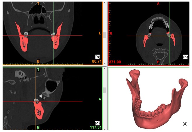
A 3D model of the mandible without impacted third molars was reconstructed by computer manipulation. The pixels of the crowns of the third molars were removed from the bone masks on each CT slice using the MIMICS software program (V16.0, Materialise, Leuven, Belgium) leaving just the root pixels. The mandibular bone was then separated as a sole mask through ROI (region of interest) extraction. A 3D model represented as a triangular mesh (also known as STL file) was created based on the mandibular bone mask. The reconstructed mandible model without IM3s was used as the baseline model for comparison (Fig. 1).
Fig. 1.
3D model of mandible reconstructed from CT images
(a) Coronal plane; (b) Axial plane; (c) Sagittal plane; (d) 3D view
2.3. Simulation design
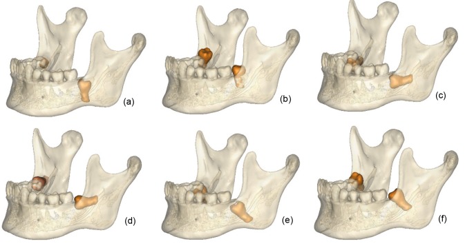
Six groups of simulated IM3 models were created, namely with fully and partially impacted third molars in vertical (V f and V p), horizontal (H f and H p), and 45° mesial-distal angulations (A f and A p). A 0.2-mm soft tissue space was created between the IM3 roots and the impacted crown surface, simulating periodontal tissue. Fig. 2 shows the location and orientation of the IM3s. Fig. 1d is the 3D mandible model without IM3s, which was used as the control. We based our models on a real case, so they were not symmetrical, to make them as close to clinical reality as possible.
Fig. 2.
3D models of six experimental groups
(a) V f: full vertical bony impaction; (b) V p: partial vertical bony impaction; (c) H f: full horizontal bony impaction; (d) H p: partial horizontal bony impaction; (e) A f: full 45° mesialangular impaction; (f) A p: partial 45° mesialangular impaction
2.4. Mechanical assignment
Using the material assigning function in Mimics, HU values from CT images of the master mandibular model were divided into nine groups based on linear tetrahedron elements created from the STL model in the 3-matic platform (V8.0, Materialise, Leuven, Belgium). The equations for bone density (ρ) and Young’s modulus (E) were based on Rho’s work (Rho et al., 1995), as shown in the following equations (the same for compact and trabecular bone):
 , ,
|
(1) |
 . .
|
(1) |
The color-coding in Fig. 3 represents non-uniform Young’s modulus distributions throughout the mandible. By taking account of the heterogeneity of bone in this way, we were able to create a more accurate model than previously reported (Kan et al., 2015; Singh et al., 2016). The range of bone and tooth density was from 0.0196 to 4.338 g/cm3 based on CT scans and the range of Young’s modulus was from 0.708 to 49.057 GPa (0.708–17.224 GPa for bone with colors blue to yellow, and 10.842–49.057 GPa for tooth with colors green to dark red). The model of tetrahedron elements, including material information, was exported from MIMICS into Abaqus (V6.13, Dassault System, Vélizy-Villacoublay, France) via an *.inp file (an input file format defined in Abaqus). The Poisson ratio of the bone was 0.3. The Young’s moduli of the IM3s and the periodontal ligament were 20 and 0.47 GPa, respectively, and their Poisson ratios were 0.3 and 0.45, respectively (Xia et al., 2013).
Fig. 3.
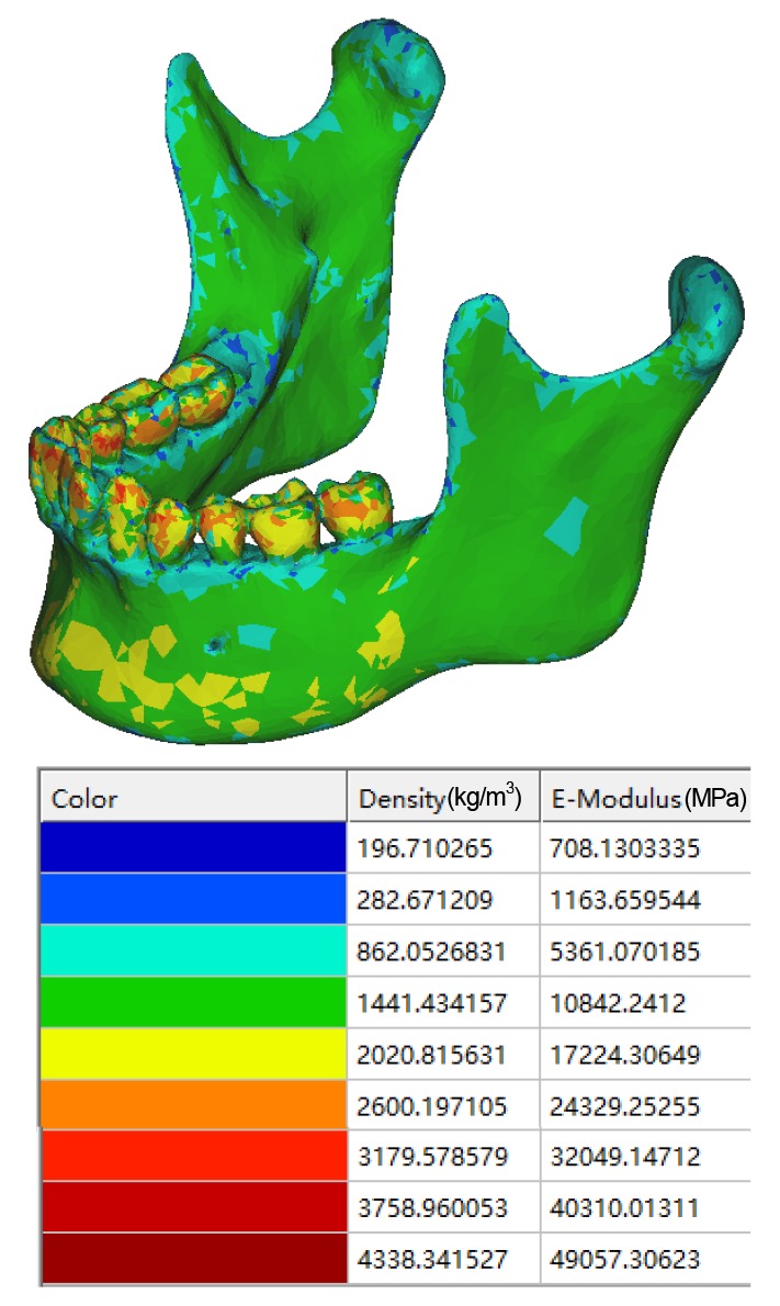
Model assigned with calculated Young’s modulus
Note: for interpretation of the references to color in this figure legend, the reader is referred to the web version of this article
2.5. Boundary conditions
Fig. 4 illustrates the loading, constraints and muscle support. Referencing from similar research (Bezerra et al., 2013; Antic et al., 2015), the most posterior and superior parts of the mandibular condyles were fixed in all six degrees of freedom (Fig. 4, black). The actions of the masticatory muscles were reproduced by an equivalent spring system (Fig. 4, yellow). The vectors of the springs were set as the lines of muscles connecting insertions with their cranial origins (Richard et al., 1992), and their stiffness was based on an estimation of the deformation of the muscles: masseter muscle, 16.35 N/mm; lateral pterygoid muscle, 12 N/mm; medial pterygoid muscle, 15 N/mm; anterior temporal muscle, 14 N/mm; posterior temporal muscle, 13 N/mm; and depressor muscles, 10.9 N/mm (Bezerra et al., 2013; Antic et al., 2015).
Fig. 4.
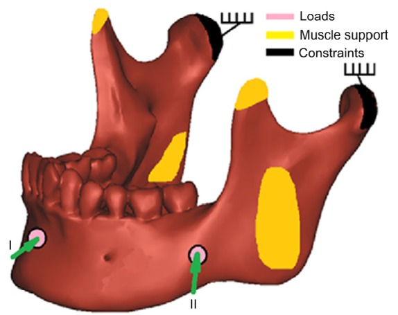
Loading and boundary constraints on mandible
Pink circles represent the locations and directions of impact loadings; yellow represents muscle attachments; and black represents fixation constraints (Note: for interpretation of the references to color in this figure legend, the reader is referred to the web version of this article)
To simulate blunt trauma, a 2000-N force, which is a common force magnitude used in trauma simulations (Antic et al., 2015), was applied perpendicularly to the facial surface in two different positions with a circular area of around 1 cm in diameter: Load I, midline of the mandible; Load II, the angle field (Fig. 4, pink). The Von Mises stress was evaluated by finite element analysis (FEA) in the whole mandible, and also in isolated regions including the angle and the condyle on both the right and left sides of the seven models.
3. Results
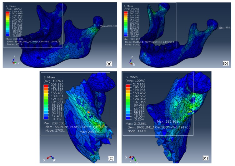
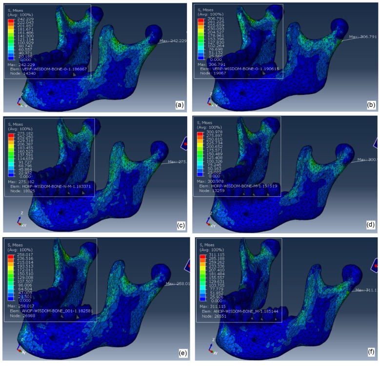
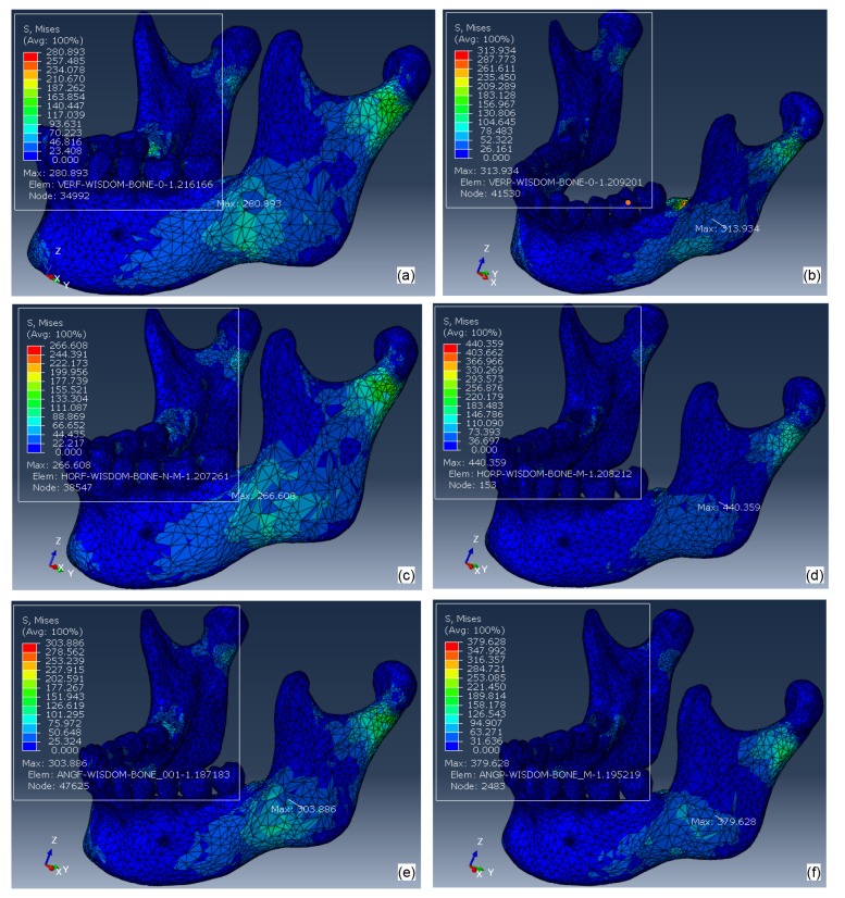
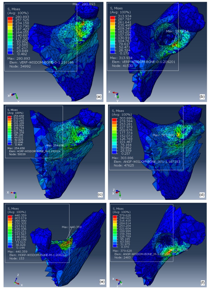
The FEA results shown in Figs. 5,6,7,8 represent color-coded Von Mises stress (MPa) distribution to the whole mandible under two loadings. In order to illustrate the stress distribution to the angular region in more detail, Figs. 5c, 5d, and 8 are enlarged displays of Von Mises stress levels in the angle of the mandible.
Fig. 5.
Von Mises stresses on mandibular bone without third molars under a 2000-N impact force from the midline of the mandible (Load I; a) and from left side of the mandibular angular area (Load II; b); Von Mises stresses in the left angular regions under a 2000-N impact force from the midline of the mandible (Load I; c) and from left side of the mandibular angular area (Load II; d)
Fig. 6.
Von Misses stress distribution to mandibles under a 2000-N impact force from the midline of the mandible (Load I) with IM3s
(a) V f; (b) V p; (c) H f; (d) H p; (e) A f; (f) A p
Fig. 7.
Von Misses stress distribution to mandibles under a 2000-N impact force from left side of the mandibular angular area (Load II)
(a) V f; (b) V p; (c) H f; (d) H p; (e) A f; (f) A p
Fig. 8.
Von Mises stress distribution to the left angle of the mandible under a 2000-N impact force from left side of the mandibular angular area (Load II) with IM3s
(a) V f; (b) V p; (c) H f; (d) A f; (e) H p; (f) A p
Fig. 5 shows the distribution of Von Mises stresses to the mandible without third molars (baseline) under a 2000-N impact force from the midline of the mandible (Load I) and from left side of the mandibular angle (Load II). The peak stresses (392.9 and 330.4 MPa) of the whole model under the two loading conditions are both located at condylar areas, which are much higher than those in angular areas (208.5 and 213.9 MPa).
Fig. 6 shows the Von Mises stresses of 6 mandibles with various orientations of IM3s under Load I. Maximum stress was always located in the left condylar region, the orientation of the IM3s having no significant effect. Fig. 7 shows the Von Mises stress distribution with IM3s under Load II. Maximum stress was always located in the left angular region, with the order of maximum stress with significant difference being greatest for model H p>A p>V p (Fig. 2 for a description of the models). Fig. 8 is the enlarged display of Von Mises stress levels in the left angular region under Load II. Stress distributions on the contralateral side were tabulated in Table 1 which summarizes the results from all the testing parameters.
Table 1.
Summary of maximum Von Mises stress in left and right angles and condyle regions of mandible with or without IM3s, under two loading conditions
| Model | Von Mises stress (MPa) |
|||||||
| Load I |
Load II |
|||||||
| Condyle |
Angle |
Condyle |
Angle |
|||||
| Left | Right | Left | Right | Left | Right | Left | Right | |
| BL | 393 | 271 | 209 | 188 | 330 | 99 | 214 | 54 |
| V p | 307 | 281 | 117 | 181 | 241 | 112 | 314 | 101 |
| V f | 242 | 211 | 136 | 169 | 234 | 114 | 281 | 161 |
| H p | 301 | 267 | 175 | 206 | 290 | 117 | 440 | 107 |
| H f | 275 | 248 | 201 | 179 | 241 | 99 | 266 | 74 |
| A p | 311 | 292 | 173 | 165 | 236 | 96 | 380 | 90 |
| A f | 258 | 228 | 174 | 163 | 241 | 119 | 304 | 93 |
BL: baseline, mandible without third molars; V f: full vertical bony impaction; V p: partial vertical bony impaction; H f: full horizontal bony impaction; H p: partial horizontal bony impaction; A f: full 45° mesialangular impaction; A p: partial 45° mesialangular impaction
4. Discussion
The mandible is the most common site of craniofacial fractures due to trauma. Depending on the studied population, angle fractures comprise approximately 12%–32% and condylar fractures 20%–43% of all mandibular fractures (Antic et al., 2015). Stress concentrates in the angle and condylar neck regions because they have relatively brittle cortical bones with narrow cross-sectional areas and hence are considered “weak” regions of the mandible. Figs. 5–7 show higher stresses distributed to these two regions during anterior and posterior blows that confirm the high risk of fracture by trauma. Fractures in the mandibular angle or condyle area are affected by their geometric shape, bone properties, stress concentration, and stress propagation from the original location. If excessive and harmful external forces are transmitted and absorbed at the angle before they propagate to the condyle area, the fracture occurs at the angle, sparing the condyle (Thangavelu et al., 2010). Clinical data reveal that mandibular fractures occur with more complicated patterns than theoretical analyses would suggest. Multiple or compound bony fractures may occur from a single impact force, including bilateral angle fractures, bilateral condylar fractures, and even one angle fracture and one condyle fracture simultaneously (Duan and Zhang, 2008; Thangavelu et al., 2010). The modality of mandible fracture is affected not only by mandibular structure and mechanical properties, but also by trauma position, force magnitude, and the speed of impact.
Table 1 shows that stresses are higher on the left than on the right side of this particular 3D model because of the asymmetrical heterogeneity of bone quality. The patient may be subjected to left side mandibular fractures. When the mandible receives a 2000-N force from the front (Load I), the maximum Von Mises stresses in the condylar areas are always higher than those in the angle of the mandible regardless of the conditions of impacted third molars or absence of IM3s. This finding is similar to Bezerra et al. (2013). It must be pointed out that this model is based on a real clinical case. The specifics will be different when using other mandibles, but the trend will be the same, i.e. the risk of mandible fracture is higher with partially than with fully impacted third molars and an impact on the mandible leads to higher risk in the angular than in the condylar area.
For the control, when a force was applied to the left side of the mandible (Load II), the highest stress was in the ipsilateral condyle followed by the ipsilateral angle area. Stresses in the contralateral condyle and angle locations were dissipated and absorbed along the bony structure before they reached the contralateral sites and so were much lower than in the ipsilateral sites. In contrast, for the experimental groups, stresses were dramatically increased at the ipsilateral angle area and not at the ipsilateral condyle. Also, stresses distributed to the contralateral condyle and angle areas among the experimental groups were very low, with very low risks of contralateral fractures.
The results for Load II with various orientations of IM3s can be explained in simplified terms by fracture mechanics which is concerned with the propagation of cracks in materials. Analytical solid mechanics can be used to calculate a driving force on a crack and to characterize the resistance of a material to fracture.
The periodontal ligament around a partially impacted third molar can be thought of as a crack in the mandible and fully impacted third molars as internal porosities or flaws. Bone is a ductile material and even cortical bone appears to be brittle. For partially impacted third molars, with the applied load to the left side of the mandible (Load II), the fracture would be type II, which is a shear stress acting parallel to the plane of the crack and parallel to the crack front. Local stresses around the hole in the stressed bone could be many times higher than the stress from the impact force. The presence of sharp corners, notches, or cracks serves to concentrate the applied stress at these points. The degree of stress magnification at the edge of the hole depends on the radius of curvature of the hole as a fracture intensity factor.
Larger cracks propagate more easily than smaller ones. The bonds at the crack tip must be stressed to the point of failure. The stress at the crack tip is a function of the stress concentration factor, which depends on the ratio of its radius of curvature to its length. Significant variations in the maximum stress can only be observed in models H p, A p, and V p, all with IM3s, under Load II with values 440, 380, and 314 MPa, increased for 16% to 21%, because the crack size is H p>A p>V p. Fully impacted third molar groups (V f, H f, and A f) do not have initial cracks. Therefore, the stresses at the angle of the mandible were not as intense as in the partially impacted third molar groups (V p, H p, and A p) regardless of their impacted orientations. The results of Table 1 characterize the fracture mechanics of fully and partially impacted third molars. Less stress is distributed to the ipsilateral and contralateral condyle and angle areas in the V p, H p, and A p groups. The same results apply to groups V f, H f, and A f. Our results confirm the study of Duan and Zhang (2008).
5. Conclusions
1. The presence of IM3 decreases the risk of condyle fracture but increases the risk of mandibular angle fracture.
2. With a front blow, irrespective of the third molars, mandibular condyles rather than the angle of the mandible bear higher risk of fracturing.
3. With a lateral impact force acting within the angular field of a mandible with third molars, the ipsilateral mandibular angle rather than condyle has a higher risk of fracturing.
4. Stresses to the mandible were higher with partially than with fully impacted third molars.
5. The angulation of both fully and partially impacted third molars did not greatly affect the stress distribution to the mandible under impact forces.
Footnotes
Project supported by the National Natural Science Foundation of China (Nos. 51375453 and 51775506) and the Natural Science Foundation of Zhejiang Province (No. LY18E050022), China
Compliance with ethics guidelines: Yun-feng LIU, Russell WANG, Dale A. BAUR, and Xian-feng JIANG declare that they have no conflict of interest.
All procedures followed were in accordance with the ethical standards of the responsible committee on human experimentation (institutional and national) and with the Helsinki Declaration of 1975, as revised in 2008 (5). Informed consent was obtained from all patients for being included in the study.
References
- 1.Afrooz PN, Bykowski MR, James IB, et al. The epidemiology of mandibular fractures in the United States, Part 1: a review of 13,142 cases from the US National Trauma Data Bank. J Oral Maxillofac Surg. 2015;73(12):2361–2365. doi: 10.1016/j.joms.2015.04.032. [DOI] [PubMed] [Google Scholar]
- 2.Antic S, Vukicevic AM, Milasinovic M, et al. Impact of the lower third molar presence and position on the fragility of mandibular angle and condyle: a three-dimensional finite element study. J Craniomaxillofac Surg. 2015;43(6):870–878. doi: 10.1016/j.jcms.2015.03.025. [DOI] [PubMed] [Google Scholar]
- 3.Bezerra TP, Silva Jr FI, Scarparo HC, et al. Do erupted third molars weaken the mandibular angle after trauma to the chin region? A 3D finite element study. Int J Oral Maxillofac Surg. 2013;42(4):474–480. doi: 10.1016/j.ijom.2012.10.009. [DOI] [PubMed] [Google Scholar]
- 4.Boffano P, Roccia F. Bilateral mandibular angle fractures: clinical considerations. Craniofac Surg. 2010;21(2):328–331. doi: 10.1097/SCS.0b013e3181cf5fbc. [DOI] [PubMed] [Google Scholar]
- 5.Chrcanovic BR, Neto Custódio AL. Considerations of mandibular angle fractures during and after surgery for removal of third molars: a review of the literature. Oral Maxillofac Surg. 2010;14(2):71–80. doi: 10.1007/s10006-009-0201-5. [DOI] [PubMed] [Google Scholar]
- 6.Cillo Jr JE, Ellis E. Management of bilateral mandibular angle fractures with combined rigid and nonrigid fixation. J Oral Maxillofac Surg. 2014;72(1):106–111. doi: 10.1016/j.joms.2013.07.008. [DOI] [PubMed] [Google Scholar]
- 7.Currey JD. Bones: Structure and Mechanics. Princeton University, Princeton, NJ; 2002. [Google Scholar]
- 8.Donadille M, Vidal N, Ella B, et al. Biangular fractures of the mandible. Rev Stomatol Chir Maxillofac. 2013;114(5):287–291. doi: 10.1016/j.revsto.2013.03.004. [DOI] [PubMed] [Google Scholar]
- 9.Duan DH, Zhang Y. Does the presence of mandibular third molars increase the risk of angle fracture and simultaneously decrease the risk of condylar fracture? Int J Oral Maxillofac Surg. 2008;37(1):25–28. doi: 10.1016/j.ijom.2007.07.010. [DOI] [PubMed] [Google Scholar]
- 10.Duarte BG, Assis D, Ribeiro-Junior P, et al. Does the relationship between retained mandibular third molar and mandibular angle fracture exist? An assessment of three possible causes. Craniomaxillofac Trauma Reconstr. 2012;5(3):127–136. doi: 10.1055/s-0032-1313355. [DOI] [PMC free article] [PubMed] [Google Scholar]
- 11.Ethunandan M, Shanahan D, Patel M. Iatrogenic mandibular fractures following removal of impacted third molars: an analysis of 130 cases. Br Dent J. 2012;212(4):179–184. doi: 10.1038/sj.bdj.2012.135. [DOI] [PubMed] [Google Scholar]
- 12.Fuselier JC, Ellis III EE, Dodson B. Do mandibular third molars alter the risk of angle fracture? J Oral Maxillofac Surg. 2002;60(5):514–518. doi: 10.1053/joms.2002.31847. [DOI] [PubMed] [Google Scholar]
- 13.Gaddipati R, Ramisetty S, Vura N, et al. Impacted mandibular third molars and their influence on mandibular angle and condyle fractures–a retrospective study. J Craniomaxillofac Surg. 2014;42(7):1102–1105. doi: 10.1016/j.jcms.2014.01.038. [DOI] [PubMed] [Google Scholar]
- 14.Halazonetis JA. The ‘weak’ regions of the mandible. Br J Oral Surg. 1968;6(1):37–48. doi: 10.1016/S0007-117X(68)80025-3. [DOI] [PubMed] [Google Scholar]
- 15.Hanson BP, Cummings P, Rivara FP, et al. The association of third molars with mandibular angle fractures: a meta-analysis. J Can Dent Assoc. 2004;70(1):39–43. [PubMed] [Google Scholar]
- 16.Iida S, Hassefeld S, Reuther T, et al. Relationship between the risk of mandibular angle fractures and the status of incompletely erupted mandibular third molars. J Craniomaxillofac Surg. 2005;33(3):158–163. doi: 10.1016/j.jcms.2004.12.001. [DOI] [PubMed] [Google Scholar]
- 17.Kan B, Coskunses FM, Mutlu I, et al. Effects of inter-implant distance and implant length on the response to frontal traumatic force of two anterior implants in an atrophic mandible: three-dimensional finite element analysis. Int J Oral Maxillofac Surg. 2015;44(7):908–913. doi: 10.1016/j.ijom.2015.03.002. [DOI] [PubMed] [Google Scholar]
- 18.Kumar SR, Sinha R, Uppada UK, et al. Mandibular third molar position influencing the condylar and angular fracture patterns. J Maxillofac Oral Surg. 2015;14(4):956–961. doi: 10.1007/s12663-015-0777-2. [DOI] [PMC free article] [PubMed] [Google Scholar]
- 19.Lee JT, Dodson TB. The effect of mandibular third molar presence and position on the risk of an angle fracture. J Oral Maxillofac Surg. 2000;58(4):394–398. doi: 10.1016/S0278-2391(00)90921-2. [DOI] [PubMed] [Google Scholar]
- 20.Ma'aita J, Alwrikat A. Is the mandibular third molar a risk factor for mandibular angle fracture? Oral Surg Oral Med Oral Pathol Oral Radiol. 2000;89(2):143–146. doi: 10.1067/moe.2000.103527. [DOI] [PubMed] [Google Scholar]
- 21.Meisami T, Sandor GKB, Lawrence HP, et al. Impacted third molars and risk of angle fracture. Int J Oral Maxillofac Surg. 2002;31(2):140–144. doi: 10.1054/ijom.2001.0215. [DOI] [PubMed] [Google Scholar]
- 22.Mercier P, Precious D. Risks and benefits of removal of impacted third molars. A critical review of the literature. Int J Oral Maxillofac Surg. 1992;21(1):17–27. doi: 10.1016/S0901-5027(05)80447-3. [DOI] [PubMed] [Google Scholar]
- 23.Naghipur S, Shah A, Elgazzar RF. Does the presence or position of lower third molars alter the risk of mandibular angle or condylar fractures? J Oral Maxillofac Surg. 2014;72(9):1766–1772. doi: 10.1016/j.joms.2014.04.004. [DOI] [PubMed] [Google Scholar]
- 24.Pakdel A, Fialkov J, Whyne CM. High resolution bone material property assignment yields robust subject specific finite element models of complex thin bone structures. J Biomech. 2016;49(9):1454–1460. doi: 10.1016/j.jbiomech.2016.03.015. [DOI] [PubMed] [Google Scholar]
- 25.Rho JY, Hobatho MC, Ashman RB. Relations of mechanical properties to density and CT numbers in human bone. Med Eng Phys. 1995;17(5):347–355. doi: 10.1016/1350-4533(95)97314-F. [DOI] [PubMed] [Google Scholar]
- 26.Rice JC. On the dependence of the elasticity and strength of cancellous bone on the apparent density. J Biomech. 1988;21(2):155–168. doi: 10.1016/0021-9290(88)90008-5. [DOI] [PubMed] [Google Scholar]
- 27.Richard TH, Vincent VH, Nisra T, et al. Modeling the biomechanics of the mandible: a three-dimensional finite element study. J Biomech. 1992;25(3):261–286. doi: 10.1016/0021-9290(92)90025-v. [DOI] [PubMed] [Google Scholar]
- 28.Ruffoni D, Fratzl P, Roschger P, et al. The bone mineralization density distribution as a fingerprint of the mineralization process. Bone. 2007;40(5):1308–1319. doi: 10.1016/j.bone.2007.01.012. [DOI] [PubMed] [Google Scholar]
- 29.Safdar N, Meechan JG. Relationship between fractures of mandibular angle and the presence and state of eruption of lower third molar. Oral Surg Oral Med Oral Pathol Oral Radiol Endod. 1995;79(6):680–684. doi: 10.1016/S1079-2104(05)80299-9. [DOI] [PubMed] [Google Scholar]
- 30.Singh P, Wang C, Ajmera DH, et al. Biomechanical effects of novel osteotomy approaches on mandibular expansion: a 3D finite element analysis. J Oral Maxillofac Surg. 2016;74(8):1658. doi: 10.1016/j.joms.2016.04.006. [DOI] [PubMed] [Google Scholar]
- 31.Tevepaugh DB, Dodson TB. Are mandibular third molars a factor for angle fractures? A retrospective cohort study. J Oral Maxillofac Surg. 1995;53(6):646–650. doi: 10.1016/0278-2391(95)90160-4. [DOI] [PubMed] [Google Scholar]
- 32.Thangavelu R, Yoganandha R, Vaidhyanathan A. Impact of impacted mandibular third molars in mandibular angle and condyle fractures. Int J Oral Maxillofac Surg. 2010;39(2):136–139. doi: 10.1016/j.ijom.2009.12.005. [DOI] [PubMed] [Google Scholar]
- 33.Venta I, Murtomaa H, Turtola L, et al. Clinical follow-up study of third molar eruption from ages 20 to 26 years. Oral Surg Oral Med Oral Pathol. 1991;72(2):150–153. doi: 10.1016/0030-4220(91)90154-5. [DOI] [PubMed] [Google Scholar]
- 34.Weiner S, Wagner HD. The material bone: structure mechanical function relations. Ann Rev Mater Sci. 1998;28(1):271–298. doi: 10.1146/annurev.matsci.28.1.271. [DOI] [Google Scholar]
- 35.Werkmeister R, Fillies T, Joos U, et al. Relationship between lower wisdom tooth position and cyst development, deep abscess formation and mandibular angle fracture. J Craniomaxillofac Surg. 2005;33(3):164–168. doi: 10.1016/j.jcms.2005.01.011. [DOI] [PubMed] [Google Scholar]
- 36.Xia ZY, Jiang FF, Chen J. Estimation of periodontal ligament’s equivalent mechanical parameters for finite element modeling. Am J Orth Dentofac Orthoped. 2013;143(4):486–491. doi: 10.1016/j.ajodo.2012.10.025. [DOI] [PMC free article] [PubMed] [Google Scholar]


