

Abstract
Deep intracranial tumor removal can be achieved if the neurosurgical robot has sufficient flexibility and stability. Towards achieving this goal, we have developed a spring-based continuum robot, namely a Minimally Invasive Neurosurgical Intracranial Robot (MINIR-II) with novel tendon routing and tunable stiffness for use in a magnetic resonance imaging (MRI) environment. The robot consists of a pair of springs in parallel, i.e., an inner inter-connected spring that promotes flexibility with decoupled segment motion and an outer spring that maintains its smooth curved shape during its interaction with the tissue. We propose a shape memory alloy (SMA) spring backbone that provides local stiffness control and a tendon routing configuration that enables independent segment locking. In this work, we also present a detailed local stiffness analysis of the SMA backbone and model the relationship between the resistive force at the robot tip and the tension in the tendon. We also demonstrate through experiments, the validity of our local stiffness model of the SMA backbone and the correlation between the tendon tension and the resistive force. We also performed MRI compatibility studies of the 3-segment MINIR-II robot by attaching it to a robotic platform that consists of SMA spring actuators with integrated water cooling modules.
I. INTRODUCTION
Brain tumor is one of the most feared complications of cancer which can have a significant impact on the quality of life of an individual. Combining intra-operative magnetic resonance imaging (MRI) system with an MRI-compatible robot having multiple degrees-of-freedom (DoFs) will enable us to develop a real-time MRI-guided neurosurgical robotic system that can potentially remove the tumor more precisely and completely. Continuum robots have been extensively researched in robotics [1] due to their flexibility and dexterity to work in confined spaces, and to safely interact with their surroundings. They can be divided into several categories such as tendon driven robots [2], [3], pre-curved concentric tubes [4], [5], locally actuated robots [6], pneumatically actuated robots [7], plastic rod based robots [8], steerable needles [9], robotic catheters [10], and modular robots [11]. These continuum robots have been adopted for various surgical applications including neurosurgery [2], ear, nose, and throat surgery [12], cardiovascular surgery [4], [5], [10], gastrointestinal surgery [13], and natural orifice translumenal endoscopic and single port surgery [14], [15].
Spring-based continuum robots have also been explored for various purposes including collision avoidance [16] and as micro-endoscopes [17]. Some of the advantages that a spring backbone offers are its relatively simple structure that would not kink during continuous bending, the elasticity that provides natural restoring force, and inherent compliance that prevents hard collision with its environment. These attractive features of a spring backbone led us to recently develop the plastic spring-based minimally invasive neurosurgical intracranial robot (MINIR-II) [18] that is tendon driven. The robot design is different from other existing spring backbone robots because it is comprised of two springs in parallel with an inner interconnected spring backbone and an outer plastic spring. The outer spring is designed to maintain the shape of the robot as separate the tendons from its environment.
While high flexibility of a continuum robot is useful for various surgical procedures, the robot may lack the stability that rigid tools provide and that is desirable for surgical procedures [19]. Thus, robots with tunable stiffness have been explored for the next generation of manipulation devices [20], [21]. Previous research on stiffness tunable designs made use of smart compliant actuators such as magneto-rheological fluid and electro-rheological fluid [22], polymers [23] and composites [24]. Mechanisms such as antagonistic configuration of non-linear springs [22], jamming [25], locking [26], and modular mechanism [27] have also been attempted. More recently, Kang et al. [28] developed a novel continuum robot that consists of the leading units (disk) and follower units (disk) with shape lockers for each segment. The follower unit is controlled by distinct rods from the leading unit and there are shape lockers to hold the rod that is connected to the leading unit. Thus, once the leading unit forms the desired shape, the follower unit locks the rod and maintains the shape, therefore providing the stability for tool manipulation in a surgical procedure.
The importance of a stable tool operation has to be underscored in robotic neurosurgery due to the critical structures that the robot may come into contact with. Following our previous work on the fully 3-D printed plastic spring-based MINIR-II robot [18], we propose a new robot design for selective actuation and stiffening of individual robot segment using shape memory alloy (SMA), a smart actuator that responses to temperature changes. We replace the plastic spring segments of MINIR-II with the SMA springs and rapid prototype customized rod-shaped disks to come up with a local stiffness tunable MINIR-II. The stiffening of the non-actuated robot segments would provide the necessary rigidity to a flexible robot and therefore stability to the brain tumor removal procedure. Inspired by the work of Choi et al. [17], we present a local stiffness model of the SMA spring backbone using the beam model. Different from Choi et al. who derived the stiffness model of a spring from a beam that has equivalent axial stiffness as the spring, we develop a modified beam model for each of our robot segment that consists of an SMA spring and a rigid rod. The modified model does not make the assumption of equivalent axial stiffness and instead contains spring-related parameters such as flexural rigidity and shear rigidity of the SMA spring based on Wahl’s spring theory [29]. We explore different combinations of tendon tensioning and segment stiffening to investigate the resultant stiffness of the robot segment and intend to verify the practicality of the robot in a gelatin phantom under MRI. The rest of the paper is organized as follows: In section II, we discuss the robot design. This is followed by the SMA spring stiffness model in section III. In Section IV, V, VI, and VII, we present the resistive force analysis, independent segment control, local stiffness characterization, and finally motion capability evaluation and MRI compatibility verification, respectively. Finally, we make some concluding remarks in section VIII.
II. Robot Design
The MINIR-II has an inner inter-connected SMA spring backbone that is divided into three segments (see Fig. 1(a)) for the multiple DoFs required in a neurosurgical procedure [18]. Each segment consists of a 3-D printed disk and a Nitinol SMA spring (Flexmet, Belgium) and there is a continuous lumen throughout the robot length. Induced by heating and cooling, SMA transforms between two phases called austenite and martensite, which have different material properties. At high temperature, SMA exists in the austenite phase, usually with a body-centered cubic crystal structure. It only deforms by slipping of the lattice structure (bonds between atoms are broken) and therefore has a higher Young’s modulus. At lower temperature, SMA exists in the martensite phase, usually with a face-centered cubic crystal structure. It deforms by detwinning (rearrangement of atoms without breaking the bonds) and therefore has a lower Young’s modulus. The SMA springs allow the robot to have segments with independently modulated stiffness. As shown in Fig. 1(c), together with the outer plastic spring which acts as a flexible shell, the entire robot is assembled into a compact robotic device. The robot is designed to have the workspace to cover deep brain tumors which have an average diameter of less than 40 mm [30] and each segment should achieve a bending angle of at least 45°. It is important to note that the bending angle is relative to the orientation (surface normal vector) of the prior disk. Hence the change in bending angle causes twice the change in the surface normal of the subsequent disk. For example, a bending angle of 45° results in a 90° orientation change of the subsequent disk as illustrated in Fig. 1(b). The diameter was selected so that the entire robot can fit inside an existing endoport (11–13 mm) used in microsurgical resection of deep-seated brain tumor [31], [32]. The lumen through the center of the robot has to be at least 4 mm to have enough room for the electrocautery wires, and suction and irrigation tubes. Therefore, the MINIR-II robot has a 65 mm length, an outer diameter of 12.6 mm, and a lumen diameter of 4.1 mm to cover the required workspace, fit in the existing endoport, and to house the required wires and cables with the electrocautery probe embedded at the tip of the end segment of the robot.
Fig. 1.
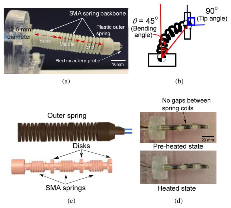
(a) Spring-based continuum robot with three segments (b) Illustration showing that the surface normal of the end segment disk has an orientation change of 90° that is twice the bending angle of 45° (c) Complete CAD model of the continuum robot with outer spring and inner inter-connected spring (d) Pictures showing the length of SMA spring before it was heated and during heating
The inner inter-connected spring backbone is the main structure of the robot and offers high flexibility and dexterity since it is able to change its compliant body into shapes that interact more gently with the brain environment. The spring length change may influence the stiffness modeling of our spring segments. To minimize the influence, we used SMA springs which have been heated to fully austenite phase so that the springs are fully contracted. Then, they are naturally cooled to the room temperature martensite phase, after which no intentional stretching is applied to the springs. Therefore, the SMA springs that form the inner backbone of the robot have minimal gaps between the spring coils. When the SMA spring is heated during an application to modulate its stiffness, the robot length changes from 70.49 mm to 70.36 mm. The 0.18% reduction is considered negligible, as shown in Fig. 1(d). Each thin disc between the segments contains multiple holes on its periphery for termination of the tendon wires and is vital for maintaining the robot shape as well as providing the moment arm for respective segment motion. The outer spring is covered with a layer of vinyl wrap that prevents contact between the SMA spring robot segments and the brain tissue.
The tendon routing process in a multi-segment continuum robot is complex and actuation of one robot segment can cause deflection of the other robot segments. As the number of segments in the robot increases, it is even more critical to have motion decoupling between the various segments. We have explored two different tendon routing configurations as shown in Fig. 2(a). The 1st configuration leads to significant coupling between the robot segments due to the straight tendon routing along the outer rim of the disks. In the 2nd configuration, the tendons are routed along the central axis of the inner interconnected spring and start branching out to the respective robot segment at the base of the corresponding segment. For instance, a tendon starts branching out at Disk 3 and are terminated at Disk 4 for end segment actuation. This tendon routing configuration minimizes coupling between segments and potentially allows independent segment control of the robot segments. This is also one of the unique features that differentiate the MINIR-II robot from other tendon-driven continuum robots [8], [33], [34] that utilized the peripheral tendon routing configuration. The effectiveness of the centrally routed tendon configuration would be assessed in section V for bending angles of up to 45° in the actuated segment. Fundamentally our design allows for independent control of even larger range of motion but due to material properties and the pitch of the SMA backbone spring, bending angles beyond 45° are yet to be investigated and in any case, beyond the scope of our requirement. As the angle increases beyond 45°, we can expect more coupling due to geometrical non-linearity and possibly also the lack of sheath around the tendons.
Fig. 2.

Different configurations of tendon routing mechanism in the robot: (a) Peripherally routed tendon configuration (b) Centrally routed tendon configuration for independent segment control (c) Illustration of end segment actuation for motion in one direction, a tendon starts branching out at Disk 3 and is terminated at Disk 4. (c) Home configuration of the robot with regular spring backbone and peripherally routed tendon configuration (d) Middle segment actuation causes undesirable deformation of the end segment with the environment. Note: The outer spring is not shown in these schematics.
The central tendon routing configuration not only has the potential to allow independent segment control but also independent segment locking using tendons. Many continuum robots that have a flexible backbone [35] are actuated by tendon driven mechanism using an external actuator due to the limited space in the robots. These robots usually have low stiffness and are not desirable due to the lack of stability required in many surgical procedures. In a case illustrated in Fig. 2(b), where there is undesirable deformation of the end segment due to bending of the middle segment, it is difficult to achieve independent stiffening of a specific robot segment (i.e. end segment) without affecting the desired motion of an actuated segment (i.e. middle segment). Continuum robots that adopt peripherally routed tendon configuration can only have their entire robot body stiffened by tensioning all the tendons. On the other hand, by tensioning a specific pair of tendons in a centrally tendon routing configuration, we can lock one segment without interfering with the motion or compliance of the other segments.
As shown in Fig. 3(a), SMA springs are utilized as the inner spring backbone in our robot and the stiffness of an individual segment can be actively controlled by changing the temperature of the corresponding SMA spring backbone which has an attached resistance temperature detector (RTD, Alpha Technics, CA, USA). Thus, combining independent segment locking by tendon tensioning and independent SMA backbone stiffening will provide more rigidity to a specific segment without interfering with the motion of the other segments. As shown in Fig. 3(b), using our design, we intend to increase the stiffness of only the end segment to eliminate the undesirable deformation while still allowing the desired motion in the middle segment. In Fig. 4, by selectively stiffening the non-actuated segments through tendon locking and SMA stiffening, ideally, only the actuated segment will bend while the other segments stay rigid. In this way, a more robust motion of the actuated segment will be generated.
Fig. 3.
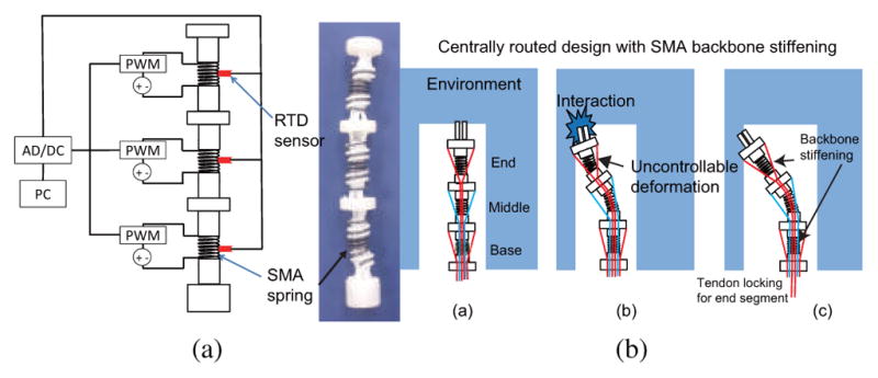
(a) Design of active local stiffness control with SMA spring backbone. Stiffness of a segment is controlled by controlling the temperature changes of the corresponding SMA spring backbone. Note: The outer spring is not shown in this schematic (b) Home configuration of the robot with the SMA spring backbone and centrally routed tendon configuration (c) Middle segment actuation results undesirable deformation of the end segment with the environment (c) SMA backbone stiffening and independent segment locking of the end segment resolve the undesirable deformation without interfering with the motion of the middle segment. Note: the outer spring is not shown in these schematics.
Fig. 4.
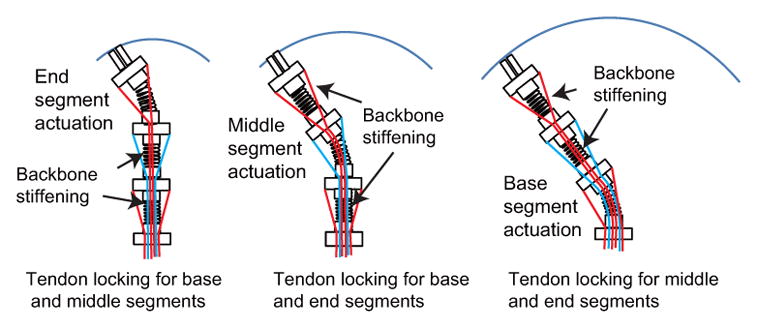
Only the actuated segment would bend by selectively stiffening the other two segments through tendon locking and SMA backbone stiffening. Note: The outer spring is not shown in these schematics
III. SMA Spring stiffness model
To model the relationship between the resistive force and the lateral deflection of a robot segment, consisting of a spring and a rod, we use a modified cantilever beam model [29] that takes into account the flexural rigidity as well as shear rigidity of the SMA spring when a point load is exerted at the tip of the robot segment. This model is still based on the assumption that the slope or bending angle of the spring lateral deflection is small. The model does not utilize the actual complex loading condition of the robot in an actual neurosurgical application. Instead, more importantly, it is used to exhibit how the stiffness of the robot segment can be modulated when the elastic modulus of the SMA spring changes due to temperature variation.
Figure 5 shows a single round-wire SMA spring backbone with mean spring diameter, D, and spring wire diameter, d, loaded by a resistive force, Fk. Since the shear modulus of the SMA backbone determines the relationship between lateral deflection and the resistive force and there is an order of magnitude difference in the modulus value of the outer and inner springs, we ignore the stiffness contribution of the outer spring in our model. When the resistive point force is applied to cause lateral displacement, y, at the tip of the rod, both an internal moment, M, and an internal shear force, V, act at the end of the spring. As we need to determine the individual contributions to lateral displacement, y, at the tip of the rod, we separate a segment into two distinct components (a spring and a rod). Using static analysis, the internal moment and the shear force can be determined by M = Fklr and V = Fk, where lr is the length of the rod. The moment, M, causes a spring deflection, δs(Moment), that can be obtained from the beam model. The shear force leads to a spring deflection, δs(Shear), that consists of two components: one component due to the deflection of the beam model and the other component due to deformation of individual spring coils. Note that the flexural rigidity of a beam, normally represented by EI (E: Young’s modulus, I: Moment of inertia), is replaced by the flexural rigidity of a spring, β [29].
Fig. 5.
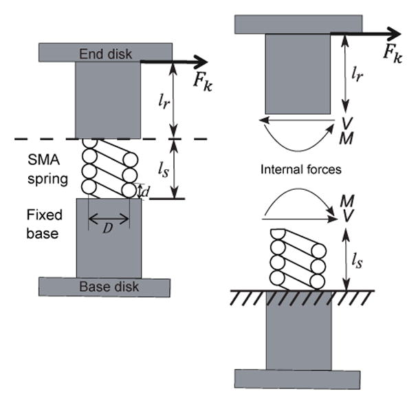
Static analysis of the robot segment modeled as a beam where V and M are the internal forces
The spring deflection at its tip, δs, can therefore be expressed as the sum of the deflection due to the moment and the deflection due to the shear force.
| (1) |
where ls and γ are the length and the shear rigidity of the spring, respectively. β and γ are given by [29]:
| (2) |
where Es, Is, Gs, R, and n are the Young’s modulus, area moment of inertia, shear modulus, mean spring coil radius, and the number of active coils of the SMA spring, respectively. The area moment of inertia of the spring is given by , where r is the wire radius of the SMA spring. Substituting β and γ into Eq. (1), we obtain:
| (3) |
Furthermore, the shear modulus and the Young’s modulus of the SMA spring can be determined by the SMA temperature which relates with martensite volume fraction, ξ. Martensite volume fraction determines the shear modulus, Gs and Young’s modulus, Es, of the SMA spring through the following relationship:
| (4) |
where GA, GM, and ν are the shear moduli in austenite phase and martensite phase, and the Poisson’s ratio, respectively. In our case, ν = 0.3. The martensite volume fraction of SMA ranges from 0 (fully austenite) to 1 (fully martensite), depending on the temperature of the SMA. Martensite volume fraction is expressed as [36]:
| (5) |
where CA is a material parameter. As, Af, ξ0, and τ are the austenite start temperature, austenite finish temperature, initial martensite volume fraction, and direct shear stress, respectively. As an approximation, the torsion moment due to the lateral force, Fk and the shear stress due to the torsion moment are given by [29]:
| (6) |
where a=D/d, is the spring index. In our case, a = 6.6. The theoretical model in this study was computed with parameters found in the work of Cheng and Desai [37] (GA = 29.57 GPa, GM = 14.12 GPa, CA = 12.81 MPa/°C).
We then determine the slope at the tip of the spring, α (refer to Fig. 6(a)) using the assumption that the spring has a constant curvature throughout its length. In the actual system, there are no gaps between the coils because the SMA backbone is heated to a temperature above the austenite finish temperature and cooled down before every experiment. We assume that the arc length of the spring does not change during the lateral bending. As shown in Fig. 6(a), δs is related to chord b through the following equation: δs = b sin(α/2). Chord b can be obtained from the geometrical relationship: b = 2c sin(α/2), where c is the radius of curvature of the SMA spring. The relationship between the arc length of the spring and the radius of curvature can be defined as . We then get . We can then obtain an equation for δs that is a function of the arc length of the spring and the slope at its tip, α, expressed as follows:
| (7) |
Fig. 6.

(a) Kinematic relationship to determine the deflection of the rod (b) Relationship between the radius of bending arc, c, and the radius of bending arc to the x-axis and z-axis. The radius of bending arc, c, and the angle, δ, can be determined by cx and cz
Using Newton’s method, we can solve for α by equating Eq. (3) and Eq. (7). α is then used to calculate the deflection of the rod due to the slope of the SMA spring. Lateral rod deflection consisting of the deflection due to the slope of the spring, δrslope, and the deflection due to the resistive force at the tip of the rod, δrloadcan thus be written as:
| (8) |
where Er and Ir are the Young’s modulus and area moment of inertia of the rod, respectively. The total deflection, y, is therefore the sum of δs, expressed in Eq. (3), and δr, expressed in Eq. (8). Thus:
| (9) |
The total deflection, y, can also be expressed as:
| (10) |
where α has to be solved numerically by equating Eq. (3) and Eq. (7). Note that using small angle assumption, the horizontal displacement due to the resistive force, δrload, can be approximated to be the same as the arc length caused by the deflection due to the loading at the tip of the rod.
IV. Resistive Force Analysis from Tendon Locking
To achieve certain stiffness in the robot segment through tendon locking, we need to make sure the robot actuators can apply a sufficient amount of force to lock the tendons. Since the stiffness model relates the lateral resistive force and the lateral displacement at the robot tip, it can be related to the amount of force required by the robot actuators through the relationship between the resistive force and the tendon tension. In this section, we develop a model for the resistive force as a function of the tendon tension during tendon locking. Due to the central tendon routing configuration, there is a fundamental difference in the kinematic relationship between the bending shape and the tendon wire length. As shown in Fig. 6(b), two opposite tendons (l1 and l3) lie in plane Bx. Likewise, the other two tendons (l2 and l4) are in plane Bz. When the robot bends by an angle, α, lying on the bending plane, α can be divided as αx and αz.
In plane Bx, we can determine the moment arm length, H and W, by the given tendon wire length, l3, shown in Fig 7. When the locking mechanism is applied on the segment, only single tendon (l3) is affected by the lateral resistive force, Fk. The moment arm length, H and W, can be expressed as:
| (11) |
where lDE is the distance from D to E and σx is the angle shown in Fig. 7. The tension force FT on the tendon can be divided into (FT)x and (FT)y, as shown in Fig. 7. (FT)x and (FT)y are given by:
| (12) |
Fig. 7.
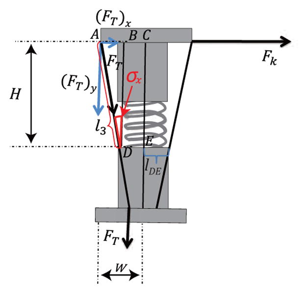
A spring model in which Fk is the resistive force generated by the lateral motion while tension, FT, is applied on the tendon, l3.
The relationship between the tension force, FT, and the resistive force, Fk, can be expressed as:
| (13) |
| (14) |
where lDE, l3, and σx are determined experimentally (see Section. VI).
V. Independent Segment Control
Our novel tendon routing configuration allows improved control over the motion of each robot segment. To verify the independent segment control, we attached the three-segment MINIR-II to a fixed wall, as shown in Figs. 8(a), 8(b), and 8(c). Vision markers were attached to the disks of all segments and a vision camera called MicronTracker (ClaroNav, Toronto, Canada) was used to track the three-dimensional position of the markers at 20 Hz and an accuracy of 0.20 mm. We tracked the position of each marker while a tendon was being pulled to actuate a single segment by the heated SMA spring actuator. In this particular experiment, the heating of SMA spring actuators was performed by manually turning on and off the power supply. Figures 9(a), 9(b) and 9(c) show that Disk 4, Disk 3, and Disk 2 were bent at various angles during actuation of the end, middle and base segments, respectively. During the same period, minimal angle changes were observed in the segments proximal to the actuated segment. When the end segment was moved, as shown in Fig. 9(a), the average changes in the angles for the base and middle segments were 0.97°, and 1.61°, respectively. While the middle segment was bent, as shown in Fig. 9(b), the average angle change of the base segment was 0.18°. While the base segment was bent, as shown in Fig. 9(c), the average angle change of the end segment was 0.87°. The actuated segment and its neighboring distal segment have nearly identical bending angles, as shown in Figs. 9(b) and 9(c). This supports the assumption that each SMA spring robot segment bends with a constant curvature throughout its length, which leads theoretically to identical bending angles between the actuated segment and its neighboring distal segment, as seen in Fig. 6(a). The larger discrepancies towards the end of the experiments could be a result of magnification of the error at larger bending angles due to the imperfect parallel alignment between the vision markers on the robot segment disks and the vision camera. Through these experiments, we verified independent segment control in our robot. It is important to note that this makes independent segment locking possible. By using independently controllable tendon routing configuration, locking the tendons connected to a target segment can stiffen the target segment without interfering with the motion of the other segments. This also leads to better detection and localization of contact along a multi-segment continuum robot which was previously studied by Bajo and Simaan [8]. If each tendon is connected to a force sensor for measurement of the tension force (interaction force during an operation), we can distinguish the specific segment interacting with the surgical environment.
Fig. 8.

Experimental setup schematics for investigating the independent segment motion by actuating (a) only end segment, (b) only middle segment, and (c) only base segment
Fig. 9.
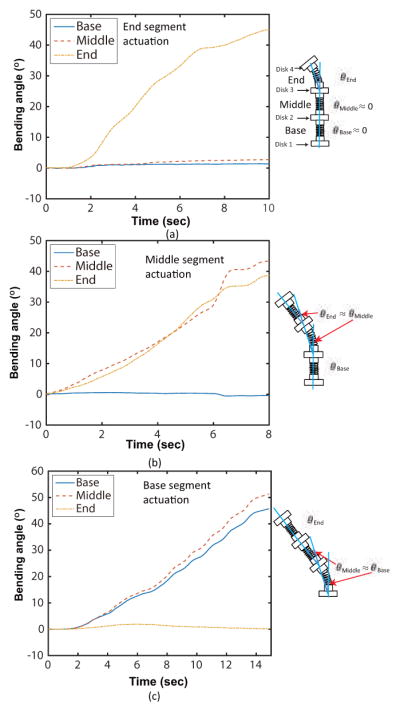
Experimental results of the independent segment motion for (a) only end segment actuation, (b) only middle segment actuation, and (c) only base segment actuation
VI. Local stiffness characterization
Local stiffness tuning is important because the robot should be able to stiffen some of its segments to achieve desired motion in the surgical environment or accomplish specific surgical tasks which need structural rigidity. By combining independent segment locking with stiffness tuning of the SMA backbone, we can adjust the stiffness of the specific segment without interfering with the motion of the other segments. In this paper, we performed the characterization experiments on the robot segment by moving its tip using the MP-285 micromanipulator (Sutter Instrument, California, USA). The wire diameter, height, mean diameter, the number of coils, and shear modulus of the outer plastic spring used in the experiment were 1.50 mm, 66.50 mm, 12.6 mm, 3, and 831.66 MPa, respectively. We assume that the force at the tip when the robot is bent at small angle is approximated to be the same as the force when the tendon is perpendicular to the MLP-10 force sensor (Transducer Techniques, LLC, California, USA) for all experiments. The stiffness values discussed in this section are the slopes of graphs that relate resistive force to lateral displacement and represent the average stiffness of the robot segment consisting of an SMA spring and a rigid rod.
A. Local stiffness changes by SMA backbone stiffening and tendon locking
To experimentally determine the local stiffness changes in a single robot segment by SMA backbone stiffening, tendon locking, and the combination of both, we performed four experiments (Cases I, II, III, and IV) as shown in Fig. 10(a). In the following characterization experiments, we used a cotton thread to connect the end disk to a force sensor attached to a micromanipulator. The elasticity of the thread allowed small lateral displacement of the micromanipulator without bending the robot by any significant angle. This ensures that the force measured by the force sensor is always the resistive force that acts perpendicular to the robot end disk. The cotton thread was chosen because its flexibility allowed it to stay taut without causing lateral deflection of the end disk when the experiments were being set up. To ensure that the cotton thread did not break and that the robot end disk was always perpendicular to the micromanipulator, only a small deflection of 5 mm was commanded in the experiments for characterization purpose. In all four cases, the SMA spring backbone was heated to a temperature above austenite finish temperature and cooled down before every experiment to ensure a stress-free condition and that there were no gaps between the spring coils. Fish wires (OmniFlex 8lb, Zebco, USA) of 0.011″ diameter were used as the tendons to connect the end disk to a screw attached to a fixed wall in Cases III and IV. The tautness of the wires can be adjusted by changing the position of the screw in and out of the fixed wall. By visual inspection, we ensured that the tendons were taut. During the experiments, the micromanipulator was moved by 5 mm and the resistive force was measured.
Fig. 10.

(a) Schematic representation of the experimental setups for the four different cases to investigate the effect of tendon locking and SMA stiffening on the local stiffness (b) Changes in resistive force when the single robot segment tip moves by a lateral displacement of 5 mm in the four different cases (c) Changes in resistive force when the tip of the three-segment robot moves by a lateral displacement of 5 mm in the four aforementioned cases
For Case I and Case II, shown in Fig. 10(a), we carried out the lateral deflection experiment when the temperature of SMA spring backbone was 40°C and 47°C, so that we can ensure the SMA spring backbone was in the non-stiffened state (fully martensite) and the stiffened state (fully austenite). The resistive force of the stiffened SMA spring-based robot segment is almost twice that of the non-stiffened SMA spring-based robot segment, as shown in Fig. 10(b). To measure the resistive force generated at the robot tip by only tendon locking, we carried out an experiment as shown in Case III in Fig. 10(a). The end of the one-segment robot was moved laterally by the micromanipulator while the SMA spring backbone was maintained at 40°C (fully martensite) and the tendons connecting the end disk of the robot to a wall was taut. In case IV shown in Fig. 10(a), the SMA spring backbone was stiffened and tendon connecting the end disk of the robot to the wall was taut. As the micromanipulator was moved laterally, the resistive force was measured.
The results, shown in Fig. 10(b), show the influence of various combinations of the tendon locking and SMA backbone stiffening on the rigidity of the one-segment robot. The combination of tendon locking and stiffened SMA spring backbone resulted in the greatest stiffness (1.5×10⁻⁴ N/m). The stiffened SMA spring backbone configuration came second with 1.1×10⁻⁴ N/m, followed by the tendon locking configuration with 1.05×10⁻⁴ N/m. The stiffness of the robot segment in case IV is merely 5.1×10⁻⁵ N/m. If the tension force that is applied to the tendon is large enough to withstand the interaction force between the robot and the environment, the tool rigidity can be enhanced by using a combination of tendon locking and stiffened SMA spring backbone.
We also performed the stiffness modulation experiment for the complete robot with three segments under identical conditions (Case I, II, III, and IV). The end disk of the three-segmented robot was connected to the force sensor using the cotton thread. All three SMA spring segments were heated simultaneously in case II while the tendons connected to the all the segments were taut in case III. In case IV, all robot segments were heated and the tendons connected to all robot segments were taut. The results shown in Fig. 10(c) confirm that the tip forces of the three-segmented robot are smaller than those of a single robot segment for all conditions. Similar to the single robot segment, the combination of tendon locking and SMA backbone stiffening leads to the highest stiffness of the three-segmented robot (9.5×10⁻⁵ N/m), followed by SMA backbone stiffening only (5.8×10⁻⁵ N/m), tendon locking only (5.3×10⁻⁵ N/m), and finally the case without either backbone stiffening and tendon locking (3×10⁻⁵ N/m).
B. Active stiffness tuning of SMA spring backbone
For active stiffness tuning, we characterized the stiffness of the SMA spring backbone by fixed lateral deflection experiments over a range of temperatures between 40°C (Case I) and 47°C (Case II), as shown by the schematic in Fig. 11(a). The lateral motion at the end of the one-segment robot was provided by the micromanipulator. The RTDs attached on the SMA spring robot segments were used to obtain their real-time temperature while a proportional-integral-derivative (PID) controller was used to control and maintain the temperature. While we maintained the temperature of the SMA spring backbone at certain values, the robot tip was moved laterally by 5 mm. The resistive force, Fk, exerted by the SMA spring backbone of the robot, was measured by the force sensor. To simulate the theoretical behavior, spring wire diameter, mean diameter, and the number of the SMA spring coils were determined to be 0.78 mm, 5.8 mm and 2.8, respectively. The resistive force, Fk used in the simulation is obtained from the experiment. Total lateral deflection (lateral displacement), y, is then calculated from Eq. (9). The characterization results of the SMA springs from the experiment are shown in Fig. 11(a). The experimental lateral deflection and theoretical lateral deflection do not have significant differences (R2-value = 0.9866 for (y)T =40°C, R2-value = 0.9917 for (y)T =42°C, R2-value = 0.9873 for (y)T =44°C, R2-value = 0.9982 for (y)T =46°C, and R2-value = 0.9978 for (y)T =47°C). The discrepancies in the shape of the plots are likely due to the non-linear behavior of the SMA spring that is anchored at one end in response to bending. The assumptions we made in the model that the arc length of the spring remains constant and that the bending angle is small such that the resistive force is always normal to the tip of the robot segment would also contribute to errors at larger bending angles. However, the model captures the important trend of SMA spring robot segment stiffness behavior and predicts within good R2-values the slopes of the plots across different SMA temperatures.
Fig. 11.
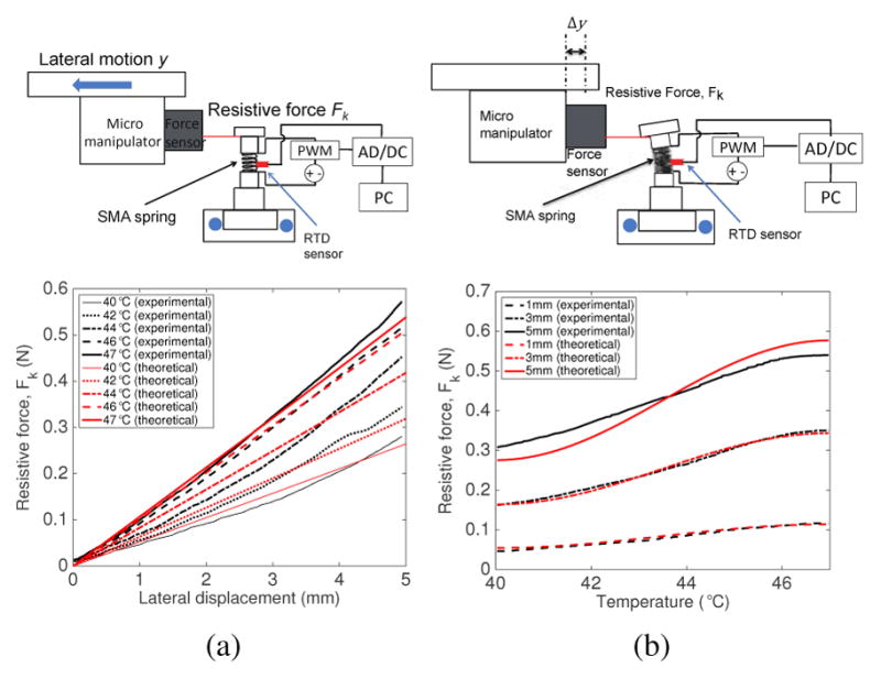
(a) Experimental setup schematic for the lateral deflection experiment and the variation of resistive force for various intermediate temperatures (b) Experimental setup schematic for the temperature variation experiment and the variation of resistive force for different lateral deflections
We also performed the temperature variation experiment, as shown by the schematic in Fig. 11(b). We maintained certain lateral displacements of 1 mm, 3 mm, and 5 mm while the SMA was heated from 40°C to 47°C. This experiment allows us to better understand the resistive force changes at different temperatures of the SMA spring. Total lateral deflection, y, is known from the experiment. Fk (theoretical value) is calculated by using Eqs. (1), (7), and (10). Figure 11(b) shows the variation of the resistive force with temperature at three specific lateral displacements of the micromanipulator. The resistive force of the SMA spring-based robot increased as the temperature of the SMA spring backbone increased. Theoretical resistive forces for 1 mm, 3 mm, and 5 mm displacements match with the experimental data well (R2-values = 0.9924 for (Fk)y=1mm, R2-values = 0.9939 for (Fk)y=3mm, and R2-values = 0.9963 for (Fk)y=5mm). The fact that the relatively biggest difference occurs with the largest lateral displacement of 5 mm could be due to the two assumptions that there is constant spring length and that the resistive force is always normal to the robot end disk.
C. Relationship between tension and resistive force
To experimentally determine the relationship between the resistive force and the tension needed for tendon locking, we performed an experiment, as shown in Fig. 12(a). An additional force sensor was added to measure the tension force in the tendon that was connected to the end disk of the robot. We kept the initial tension in the tendon to be 0.04 N, so that the tendon was initially taut. While the end of the robot was moved laterally by the micromanipulator, both the tension in the tendon and the resistive force were being measured. The results for the experiment are shown in Fig. 12(b). It can be observed that the tension applied was 5.02 times the exerted resistive force for 5 mm lateral displacement of the micromanipulator. Therefore, considering the safety of the device, we need to ensure that our actuators are able to generate and withstand approximately 6 times the amount of force we need at the robot tip. The theoretical resistive force data from Eq. (14) discussed in Section IV matches the experimental data well (R2-value = 0.9931).
Fig. 12.
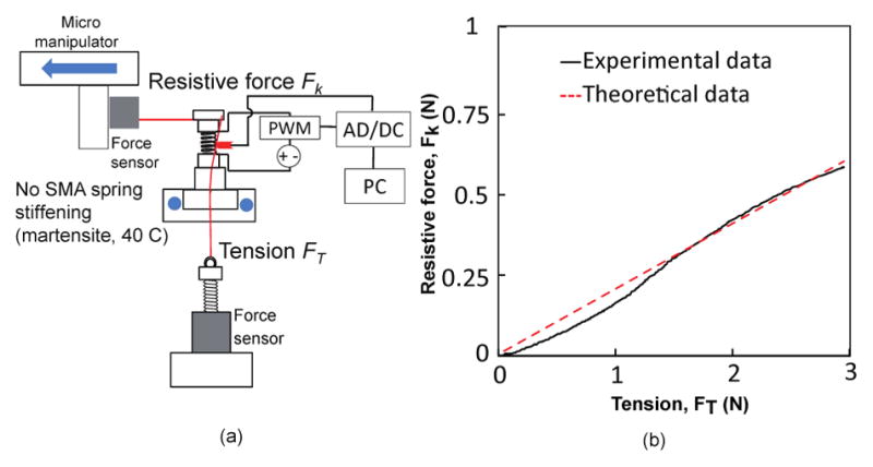
(a) Schematic of experimental setup and (b) variation of the resistive force, Fk and tendon tension, FT
VII. Motion Capability Evaluation and MRI Compatibility Verification
As shown in Fig. 13(a), we developed an MRI-compatible robotic platform consisting of Nitinol SMA spring actuators (Flexmet, Belgium) with integrated water cooling modules and attached the 3-segment MINIR-II robot to the robot holder on the platform. The entire system is composed of the robotic platform, water reservoir, air compressor, and a computer with an analog-to-digital-converter (ADC) board. More details about the robotic platform can be found in the work by Cheng and Desai [38]. An experiment was performed to measure the accurate surface temperature of the robot wrapped in the vinyl wrap, as shown in Fig. 13(b). The real-time surface temperatures at three locations on the robot surface close to the three SMA spring segments were recorded while all three SMA springs were heated to 47°C. As shown in Fig. 13(c), the surface temperatures at all three locations were less than 35°C during the 5-minute period that the SMA springs were maintained at 47°C. This is lower than the body temperature and is siginficantly lower than the brain necrosis temperature of approximately 44°C [39]. The air gap between the SMA spring backbone and the outer spring plays a significant role in lowering the surface temperature of the robot. The robot head was designed to have a specific slot for the EndoScout® sensor (Robin Medical, Inc., Baltimore, MD, USA), as shown in Fig. 14(d). We inserted the robot part of the platform into a gelatin (Knox, USA) slab and performed a robot motion experiment in the gelatin slab to verify motion capability and MRI compatibility of the robot in a brain simulated environment. Figure 14(a) shows the experimental setup of the MRI compatibility test. A head coil was placed over the robot/gelatin slab at the center of the MRI scanner. In the MRI scanner, we used an on-off control (visual inspection of robot motion) when heating the SMA spring actuators. Before actuating the robot, we took 50 MR images, to evaluate the degree of image distortion caused by the robot and determine the signal-to-noise ratio (SNR) changes of MR images during MRI scanning. We then heated one SMA spring actuator to bend the end segment of the robot to the right before actively cooling it down and heating the antagonistic SMA spring actuator to bend the end robot segment to the left. During the actuation process, an additional 50 MRI images were taken. During this test, we performed the resistive heating and active cooling of SMA spring actuators, but SMA backbone stiffening was not activated. It can be seen from Fig. 14(b) that the motion of the robot end segment in the gelatin phantom did not cause any significant shape change in the non-stiffened proximal segments. The SNR was calculated as a ratio of the mean value of an area of pixels at the center of the image (black box) and the standard deviation of an area of pixels at the lower-right corner of the image (red box) as shown in Fig. 14(b) [40]. The average and standard deviation of SNR of the 50 images with non-actuated MINIR-II was 25.98 ± 0.60. During the actuation of the robot, the average and standard deviation of SNR of the 50 images was 25.95±0.76, resulting in a 0.8% SNR drop (See Fig. 14(c)). It is confirmed that there was minimal distortion caused by the actuation of the robot. Furthermore, we also performed additional test where only SMA backbone stiffening (heating) was activated. To enhance quality of the MR images, we used a body coil, instead of the head coil. To heat the inner SMA spring backbone, it needs to be insulated from the gelatin. Thus, the three segmented robot with the only inner SMA spring backbone was wrapped in a vinyl wrap during the SMA backbone stiffening (heating) as shown in Fig. 14(d). As a result, the SNRs of each image for non-stiffened backbone and stiffened backbone are 243.93 and 235.20, respectively. Minimal distortion (3.6% SNR drop) by the SMA backbone stiffening (heating) was observed (See Fig. 14(e)).
Fig. 13.

(a) Experimental platform built to hold and actuate the MINIR-II in the MRI compatibility test (b) Experimental setup to measure the surface temperatures at three locations close to the three SMA spring segments of the robot (b) Real-time data of the SMA spring temperature and the surface temperature of the robot at three locations
Fig. 14.

(a) Experimental setup during MRI compatibility test; MR images of MINIR-II in a gelatin slab: (b) MR images of the MINIR-II in the non-actuated state and actuated states (c) SNR changes when the MINIR-II was in the non-actuated state and the actuated state (d) Actual picture and schematic of the MINIR-II with integrated EndoScout® sensor; (e) MR images of MINIR-II in a gelatin slab without SMA backbone stiffening (left) and with SMA backbone stiffening (right)
VIII. Discussion and Conclusion
We have developed a spring-based continuum robot that has an inner inter-connected SMA spring backbone with multiple segments and an outer plastic spring, whereby the stiffness of the inner inter-connected spring can be tuned based on the temperature of the SMA spring. The robot uses a tendon driven mechanism with a unique tendon routing configuration to avoid coupling between the robot segments and achieve independent segment locking. Advanced motion capabilities can be achieved by using independent segment locking and SMA spring backbone stiffening. Compared to the interlaced robot proposed by Kang et al. [28], the MINIR-II robot has a relatively simple structure of a continuous spring and still provides similar function of robot stiffening and tool stability. The MINIR-II robot is different from the interlaced robot such that we focused our effort on achieving independent stiffening of the non-actuated robot segment in MINIR-II while the interlaced robot’s main strength is to achieve tool stability through pose control in any configuration using follow-the-leader deployment. The MINIR-II robot can control the stiffness of each segment easily at any time during the surgery through temperature variation of the SMA spring backbone while the interlaced robot may need more complex steps to change and maintain a desired pose. The resistive force generated from SMA spring-based segment was analyzed in terms of its stiffness. We performed experiments to verify our SMA spring stiffness model and determine the relationship between the resistive force and the tension in the connecting tendons. We also verified that structural rigidity of MINIR-II is greatly improved by using a combination of tendon locking and SMA spring backbone stiffening. We tested the motion capability of the robot in a gelatin phantom and verified its MRI-compatibility. In our future work, we plan to address the problem of deployment of the robot, including the manufacture of a customized head frame that allows trajectory adjustment and insertion of the robot. We also plan to integrate piezoelectric motor actuators with the MINIR-II robot.
Acknowledgments
Research reported in this publication was supported by the National Institute Of Biomedical Imaging And Bioengineering of the National Institutes of Health under Award Number R01EB015870. The content is solely the responsibility of the authors and does not necessarily represent the official views of the National Institutes of Health.
We would like to acknowledge Dr. Mahamadou Diakite for his assistance in the MRI compatibility tests.
Biographies

Dr. Yeongjin Kim is currently an Assistant Professor in the Department of Mechanical Engineering at Incheon National University. He received his B.S, M.S. and Ph.D. in Mechanical Engineering in 2006, 2008 and 2012, respectively, from the Korea Advance Institute of Science and Technology. He was also a Research Associate in the Department of Mechanical Engineering at University of Maryland, College Park. His research interests are primarily in the area of MR-compatible surgical robotics, rehabilitation robotics, grasping, and mechanical cancer diagnosis.

Shing Shin Cheng is currently working towards his Ph.D. degree in Robotics in the Wallace H. Coulter Department of Biomedical Engineering at Georgia Institute of Technology. He earned his B.S. in Mechanical Engineering from Johns Hopkins University in 2013 and M.S. in Mechanical Engineering from the University of Maryland, College Park in 2016. His research interests include surgical robotics, medical devices, and smart actuators.

Dr. Jaydev P. Desai is currently a Professor and BME Distinguished Faculty Fellow in the Wallace H. Coulter Department of Biomedical Engineering at Georgia Institute of Technology. He completed his undergraduate studies from the Indian Institute of Technology, Bombay, India, in 1993. He received his M.A. in Mathematics in 1997, M.S. and Ph.D. in Mechanical Engineering and Applied Mechanics in 1995 and 1998 respectively, all from the University of Pennsylvania. He was also a Post-Doctoral Fellow in the Division of Engineering and Applied Sciences at Harvard University from 1998–1999. He is a recipient of several NIH R01 awards and NSF CAREER award. His research interests include surgical robotics, MEMS-based cancer diagnosis, micro-scale cell and tissue characterization, haptics, and grasping. He is a senior member of the IEEE and a fellow of ASME and AIMBE. He is also the Editor-in-Chief of the Journal of Medical Robotics Research.
References
- 1.Walker ID, Choset H, Chirikjian GS. Springer Handbook of Robotics. Springer; 2016. Snake-like and continuum robots; pp. 481–498. [Google Scholar]
- 2.Ho M, Kim Y, Cheng SS, Gullapalli R, Desai JP. Design, development, and evaluation of an MRI-guided SMA spring-actuated neurosurgical robot. The International Journal of Robotics Research. 2015 doi: 10.1177/0278364915579069. 0278364915579069. [DOI] [PMC free article] [PubMed] [Google Scholar]
- 3.Li Z, Wu L, Ren H, Yu H. Kinematic comparison of surgical tendon-driven manipulators and concentric tube manipulators. Mechanism and Machine Theory. 2017;107:148–165. [Google Scholar]
- 4.Sears P, Dupont P. A steerable needle technology using curved concentric tubes. Intelligent Robots and Systems, 2006 IEEE/RSJ International Conference on; IEEE; 2006. pp. 2850–2856. [Google Scholar]
- 5.Webster RJ, III, Romano JM, Cowan NJ. Kinematics and calibration of active cannulas. Robotics and Automation, 2008. ICRA 2008. IEEE International Conference on; IEEE; 2008. pp. 3888–3895. [Google Scholar]
- 6.Ayvali E, Liang CP, Ho M, Chen Y, Desai JP. Towards a discretely actuated steerable cannula for diagnostic and therapeutic procedures. The International Journal of Robotics Research. 2012;31(5):588–603. doi: 10.1177/0278364912442429. [DOI] [PMC free article] [PubMed] [Google Scholar]
- 7.Pritts MB, Rahn CD. Design of an artificial muscle continuum robot. Robotics and Automation, 2004. Proceedings. ICRA’04. 2004 IEEE International Conference on; IEEE; 2004. pp. 4742–4746. [Google Scholar]
- 8.Bajo A, Simaan N. Kinematics-based detection and localization of contacts along multisegment continuum robots. IEEE Transactions on Robotics. 2012 Apr;28(2):291–302. [Google Scholar]
- 9.Parittotokkaporn T, Frasson L, Schneider A, Huq SE, Davies BL, Degenaar P, Biesenack J, Baena FM. Soft tissue traversal with zero net force: Feasibility study of a biologically inspired design based on reciprocal motion. Robotics and Biomimetics, 2008. ROBIO 2008. IEEE International Conference on; IEEE; 2009. pp. 80–85. [Google Scholar]
- 10.Khan EM, Frumkin W, Ng GA, Neelagaru S, Abi-Samra FM, Lee J, Giudici M, Gohn D, Winkle RA, Sussman J, et al. First experience with a novel robotic remote catheter system: Amigo™ mapping trial. Journal of Interventional Cardiac Electrophysiology. 2013;37(2):121–129. doi: 10.1007/s10840-013-9791-9. [DOI] [PubMed] [Google Scholar]
- 11.Zhang H, Gonzalez-Gomez J, Me Z, Cheng S, Zhang J. Development of a low-cost flexible modular robot gz-i. 2008 IEEE/ASME International Conference on Advanced Intelligent Mechatronics; IEEE; 2008. pp. 223–228. [Google Scholar]
- 12.Simaan N, Taylor R, Flint P. Medical Image Computing and Computer-Assisted Intervention–MICCAI 2004. Springer; 2004. High dexterity snake-like robotic slaves for minimally invasive telesurgery of the upper airway; pp. 17–24. [Google Scholar]
- 13.Wang K, Yan G, Jiang P, Ye D. A wireless robotic endoscope for gastrointestine. Robotics, IEEE Transactions on. 2008;24(1):206–210. [Google Scholar]
- 14.Dallemagne B, Marescaux J. The anubis™ project. Minimally Invasive Therapy & Allied Technologies. 2010;19(5):257–261. doi: 10.3109/13645706.2010.514741. [DOI] [PubMed] [Google Scholar]
- 15.Suzuki N, Hattori A, Tanoue K, Ieiri S, Konishi K, Tomikawa M, Kenmotsu H, Hashizume M. Medical Imaging and Augmented Reality. Springer; 2010. Scorpion shaped endoscopic surgical robot for notes and sps with augmented reality functions; pp. 541–550. [Google Scholar]
- 16.Yoon H-S, Yi B-J. A 4-DOF flexible continuum robot using a spring backbone. Mechatronics and Automation, 2009. ICMA 2009. International Conference on; IEEE; 2009. pp. 1249–1254. [Google Scholar]
- 17.Choi D-G, Yi B-J, Kim W-K. Design of a spring backbone micro endoscope. Intelligent Robots and Systems, 2007. IROS 2007. IEEE/RSJ International Conference on; IEEE; 2007. pp. 1815–1821. [Google Scholar]
- 18.Kim Y, Desai JP. Design and kinematic analysis of a neuro-surgical spring-based continuum robot using SMA spring actuators. Intelligent Robots and Systems (IROS), 2015 IEEE/RSJ International Conference on; IEEE; 2015. pp. 1428–1433. [Google Scholar]
- 19.Loeve A, Breedveld P, Dankelman J. Pulse. 3. Vol. 1. IEEE; 2010. Scopes too flexible… and too stiff; pp. 26–41. [DOI] [PubMed] [Google Scholar]
- 20.Cianchetti M, Ranzani T, Gerboni G, Nanayakkara T, Althoefer K, Dasgupta P, Menciassi A. Soft robotics technologies to address shortcomings in today’s minimally invasive surgery: the STIFF-FLOP approach. Soft Robotics. 2014;1(2):122–131. [Google Scholar]
- 21.Kim Y-J, Cheng S, Kim S, Iagnemma K. Design of a tubular snake-like manipulator with stiffening capability by layer jamming. Intelligent Robots and Systems (IROS), 2012 IEEE/RSJ International Conference on; IEEE; 2012. pp. 4251–4256. [Google Scholar]
- 22.Van Ham R, Sugar T, Vanderborght B, Hollander K, Lefeber D. Review of actuators with passive adjustable compliance/controllable stiffness for robotic applications. IEEE Robotics and Automation Magazine. 2009;16(3):81–94. [Google Scholar]
- 23.Loeve AJ, Bosma JH, Breedveld P, Dodou D, Dankelman J. Polymer rigidity control for endoscopic shaft-guide ‘Plastolock’—a feasibility study. Journal of Medical Devices. 2010;4(4):045001. [Google Scholar]
- 24.Shan W, Lu T, Majidi C. Soft-matter composites with electrically tunable elastic rigidity. Smart Materials and Structures. 2013;22(8):085005. [Google Scholar]
- 25.Jiang A, Aste T, Dasgupta P, Althoefer K, Nanayakkara T. Granular jamming with hydraulic control. ASME 2013 International Design Engineering Technical Conferences and Computers and Information in Engineering Conference; American Society of Mechanical Engineers; 2013. pp. V06AT07A021–V06AT07A021. [Google Scholar]
- 26.Moses MS, Kutzer MDM, Ma H, Armand M. A continuum manipulator made of interlocking fibers. Robotics and Automation (ICRA), 2013 IEEE International Conference on; IEEE; 2013. pp. 4008–4015. [Google Scholar]
- 27.Ranzani T, Cianchetti M, Gerboni G, De Falco I, Petroni G, Menciassi A. A modular soft manipulator with variable stiffness. 3rd joint workshop on new technologies for computer/robot assisted surgery; 2013. [Google Scholar]
- 28.Kang B, Kojcev R, Sinibaldi E. The first interlaced continuum robot, devised to intrinsically follow the leader. PloS one. 2016;11(2):e0150278. doi: 10.1371/journal.pone.0150278. [DOI] [PMC free article] [PubMed] [Google Scholar]
- 29.Wahl AM. Mechanical springs. Penton Publishing Company; 1944. [Google Scholar]
- 30.Linzer D, Ling S, Villalobos H, Raub W, Jr, Wu X, Ting J, Berti A, Landy H, Markoe A. Gamma knife radiosurgery for large volume brain tumors: An analysis of acute and chronic toxicity. Stereotactic and functional neurosurgery. 1998;70(Suppl 1):11–18. doi: 10.1159/000056402. [DOI] [PubMed] [Google Scholar]
- 31.Jo KW, Shin HJ, Nam DH, Lee JI, Park K, Kim JH, Kong DS. Efficacy of endoport-guided endoscopic resection for deep-seated brain lesions. Neurosurgical review. 2011;34(4):457–463. doi: 10.1007/s10143-011-0319-4. [DOI] [PubMed] [Google Scholar]
- 32.Ding D, Starke RM, Crowley RW, Liu KC. Endoport-assisted microsurgical resection of cerebral cavernous malformations. Journal of Clinical Neuroscience. 2015;22(6):1025–1029. doi: 10.1016/j.jocn.2015.01.004. [DOI] [PubMed] [Google Scholar]
- 33.Gravagne I, Walker I. Kinematic transformations for remotely-actuated planar continuum robots. Robotics and Automation, 2000. Proceedings. ICRA ’00; 2000. pp. 19–26. [Google Scholar]
- 34.Jones BA, Walker ID. Kinematics for multisection continuum robot. IEEE Transactions on Robotics. 2006 Feb;22(1):43–57. [Google Scholar]
- 35.Walker ID. Continuous backbone continuum robot manipulators. ISRN Robotics. 2013;2013 [Google Scholar]
- 36.Brinson L. One-dimensional constitutive behavior of shape memory alloys: Thermomechanical derivation with non-constant material functions and redefined martensite internal variable. Journal of Intelligent Material Systems and Structures. 1993;4(2):229–242. [Online]. Available: http://jim.sagepub.com/content/4/2/229.abstract. [Google Scholar]
- 37.Cheng SS, Desai JP. Towards high frequency actuation of sma spring for the neurosurgical robot – MINIR-II. ICRA 2015 International Conference on Robotics and Automation; IEEE; 2015. [Google Scholar]
- 38.Cheng SS, Kim Y, Desai JP. Towards real-time SMA control for a neurosurgical robot: MINIR-II. International Symposium on Robotics Research; 2015. (In Press) [Google Scholar]
- 39.Matsumi N. Thermal damage threshold of brain tissue. Okayama Igakkai Zasshi (Journal of Okayama Medical Association) 1989;101(11–12):1049–1061. [Google Scholar]
- 40.Gassert R, Moser R, Burdet E, Bleuler H. MRI/fMRI-compatible robotic system with force feedback for interaction with human motion. Mechatronics, IEEE/ASME Transactions on. 2006;11(2):216–224. [Google Scholar]