

Abstract
Extracorporeal membrane oxygenation (ECMO) is a life support system that circulates the blood through an oxygenating system to temporarily (days to months) support heart or lung function during cardiopulmonary failure until organ recovery or replacement. Currently, the need for high levels of systemic anticoagulation and the risk for bleeding are main drawbacks of ECMO that can be addressed with a redesigned ECMO system. Our lab has developed an approach using MEMS (microelectromechanical systems) fabrication techniques to create novel gas exchange membranes consisting of a rigid silicon micropore membrane (SμM) support structure bonded to a thin film of gas-permeable polydimethylsiloxane (PDMS). This study details the fabrication process to create silicon membranes with highly uniform micropores that have a high level of pattern fidelity. The oxygen transport across these membranes was tested in a simple water based bench-top set-up as well in a porcine in vivo model. It was determined that the mass transfer coefficient for the system using SμM-PDMS membranes was 3.03 ± 0.42 mL O2 min−1 m−2 cmHg−1 with pure water and 1.71 ± 1.03 mL O2 min−1 m−2 cmHg−1 with blood. An analytic model to predict gas transport was developed using data from the bench-top experiments and validated with in vivo testing. This was a proof of concept study showing adequate oxygen transport across a parallel plate SμM-PDMS membrane when used as a membrane oxygenator. This work establishes the tools and the equipoise to develop future generations of silicon micropore membrane oxygenators.
Keywords: Extracorporeal membrane oxygenator, ECMO, artificial lung, silicon micropore membrane, heart lung bypass, respiratory assist device
Graphical Abstract

1.1 Introduction
Extracorporeal membrane oxygenation (ECMO) is a life support system that circulates the blood through an oxygenating system to temporarily (days to months) support heart or lung function during cardiopulmonary failure until organ recovery or replacement. Over the past two decades, ECMO has become more common, and is now used to treat roughly 7000 patients annually worldwide, including a fivefold increase over the past decade in the adult population1,2. Still, commercially available ECMO systems have considerable drawbacks and limitations, including the most common complication of bleeding3. There have been several approaches to improve on ECMO technology including further refinement of hollow fiber membrane technology, or utilization of microfluidic soft lithography to approximate human lung architecture4. However, these approaches have inherent limitations that lead to membrane fouling and risk of thrombosis, necessitating the use of high levels of anticoagulation. To improve on these systems, our lab has adopted an alternative strategy utilizing MEMS (microelectromechanical systems) fabrication techniques to create novel gas exchange membranes consisting of a rigid silicon micropore membrane (SμM) support structure bonded to a thin film of gas-permeable polydimethylsiloxane (PDMS). The silicon membrane support structure provides structural integrity, which allows for the PDMS layer to be an order of magnitude thinner than commercially available polymer membranes. We anticipate that the composite SμM-PDMS membranes will yield efficient oxygen transport, and can be arranged in a parallel plate design that can be readily modified to finely tune the blood flow path to allow for optimized hemocompatibility. The goal is to house the SμM-PDMS membranes in a compact design with an improved hemocompatibility profile compared to the current standard of care. In this paper, we develop a proof-of-concept parallel plate membrane oxygenator and demonstrate in vivo feasibility in a porcine model.
2.0 Materials/Methods
2.1 Fabrication of the Silicon-PDMS Membrane and Flow Cell
The fabrication of the SμM-PDMS membrane is based on prior work in this lab on silicon nanopore membranes, with adaptations specific to this project5–7. Briefly, the prior work describes a process by which controlled growth of silicon dioxide produces arrays of sub-100 nm rectangular pores within silicon wafers (Figure 1A). For this study, the process was modified to utilize lithographic patterning to define pore dimensions at the 500 nm–1000 nm range. To create the PDMS layer of the composite membrane, a multilayered sacrificial substrate was used to transfer the thin layer (3–5 um) of polydimethylsiloxane (PDMS) to the SμM (Figure 1B). A thick layer of Sylgard 184 PDMS (Dow Corning, Midland, MI) was mixed at a monomer-to-crosslinker ratio of 10:1, spin coated (500 RPM for 10s) onto a 4 inch silicon wafer, and cured for 2 hours at 80°C. Then, the surface was treated with O2 plasma (100W, 20s, 200SCCM) to make the surface wettable. Subsequently, a second sacrificial layer of polyvinyl alcohol (PVA) 5% w/w in water was spin coated (1000 RPM, 30s) onto the PDMS layer, cured at 60°C for 1 hour, and slowly cooled to room temperature. As the final thin layer of PDMS, mixed Sylgard 184 was diluted with hexanes (Sigma Aldrich) at a 1:1 ratio, and spin coated directly on top of the layer of PVA (6000 RPM, 300s). The thick PDMS-PVA-thin PDMS construct was peeled off the silicon wafer and bonded to the SμM membrane using oxygen plasma to activate both surfaces (100W, 20s, 200 SCCM). After at least 12 hours of bonding time, the membranes were submerged in 70°C water for 3–4 hours to fully dissolve the PVA layer and release the thick PDMS layer, leaving the thin PDMS layer (3–5 microns) bonded to the SμM.
Figure 1.
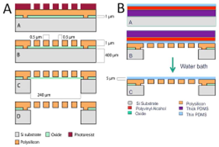
Schematic of the fabrication of the silicon micropore membranes (1A) and of the PDMS transfer process (1B) to achieve 3–5 micron thick PDMS layer bonded to the silicon micropore membranes
2.3 Oxygen Diffusion Through Membranes
Oxygen diffusion through the SμM-PDMS membranes was determined by measuring the oxygen concentration change in degassed water after passing over the membrane, similar to previous work and shown in Fig. 2.8,9 A 6 cm × 1 cm PDMS-SμM membrane was mounted into a machined polyether ether ketone (PEEK) flow cell with a water channel height of 200 microns, such that the PDMS would be in contact with the water while the silicon support structure was exposed to sweep gas. Oxygen was then removed from water by bubbling in nitrogen gas to establish a low starting concentration of oxygen in the water. This degassed water was pumped across the membrane at a rate of 10 mL/min (Cole Palmer pump) with an optical oxygen sensor (NeoFox inline optical oxygen sensor - Ocean Optics, Dunedin, FL) at the distal end of the device (Figure 2). For each measurement, pure oxygen was used to pressurize the sweep gas and the resulting oxygen flux into the water from the membrane was determined by the oxygen sensor. The pressurized sweep gas of pure oxygen was held between 2 and 10 PSI to establish a trans-membrane partial pressure gradient of between 800 and 1200 mmHg. The upper range of these pressures was chosen to be less than half the pressure at which mechanical failure occurred of the SμM-PDMS membrane.
Figure 2.

Diagram (A) and picture (B) of experimental setup to measure oxygen diffusion into water
At the end of each test, the oxygen supply was removed and the sweep gas was vented. The coupled oxygen permeability constant (k) was determined using the following formula (mL O2 min−1 m−2 cmHg−1), where [O2] is the concentration of oxygen before and after the device (ml O2 ml water−1), Q is the flow rate of fluid (ml water min−1), Am is the membrane area (m2), and P is the partial pressure of oxygen in the sweep gas and in the water at the start and end of the membrane (cm Hg).
| (Eq1) |
2.4 Blood oxygenation in an In Vivo Porcine Model
Oxygen permeability for the SμM-PDMS membranes arranged in a parallel plate geometry was determined in an in vivo porcine model. Four membranes were secured into each half of a titanium flow cell using epoxy (Epoxy Technology OD2002) for eight total membranes per device (Figure 4). The two halves were then assembled using 125 μm silicone gaskets to guide the sweep gas path, as well as seal the blood path. The channel height of the blood flow path was estimated to be approximately 100–125 μm for each of the devices, with some uncertainly related to gasket compression. The channel flow path was roughly 4 cm wide and 6.5 cm long. Each flow cell was leak tested with water prior to each experiment. Over a series of three separate experiments, ~55 kilogram Yorkshire pigs were sedated, anesthetized, anticoagulated with heparin to goal ACT >400 seconds, and their trachea were intubated. Two 16 French venous sheaths were placed into the right internal jugular and the left femoral vein of each pig. Using a mixture of nitrogen and oxygen as the inhaled gas, the pig’s peripheral oxygen saturation was lowered to 80% for the entirety of the study. After the pigs reached a steady oxygen saturation state, a sweep gas of pure oxygen was applied to the back side of the silicon membranes. Blood was pulled from the femoral vein and pumped through the blood channel of the flow cell and returned to the animal via the internal jugular vein. In these experiments, blood flow rate was mostly kept at 25 mL/min, with some samples taken at 15 and 50 mL/min to examine the effect of flow rate on oxygen flux into blood. Samples of blood were taken proximal and distal of each the device simultaneously every 15 minutes for 3 hours. Blood samples were run on an iStat ABG - G8 cartridge to determine O2 content in ml O2 per ml of blood (Eq2)10, where Hg is the hemoglobin of the blood (mg ml−1), SaO2 is the percent of hemoglobin that are bound to oxygen, and PaO2 is the partial pressure of oxygen in the blood (mm Hg).
Figure 4.

O2 permeability for three separate flow cells ± SD. Combining all flow cells, average gas permeability was found to be 1.71 ml O2 STP/min/m2/cm Hg ± 1.03 ml O2 STP/min/m2/cm Hg (n=7 for each of the three flow cells).
| (Eq2) |
The difference in oxygen content pre- and post-device was used to determine the gas permeability of the membranes in this device. This analysis was based on a modified Eq. 1, where Q is broken into V (volume of blood within the device in ml) and t (residence time within the device in minutes)(Eq3).
| (Eq3) |
At the conclusion of the study, the animal was sacrificed as per protocol that was approved by the Institutional Animal Care and Use Committee (IACUC) at Surpass Inc CRO (Mountain View, CA) and the assembly was dismantled and inspected for gross clots and membrane defects.
2.5 Model Formulation
A model to predict and describe oxygen transport in the PDMS-SμM oxygenator was developed to provide insight into variables to focus on for future refinement. Similar to prior gas transport models, this model also accounts for non-porous regions of the membranes which create a heterogeneous gas exchange surface. For details on model derivations please see supplementary information, where the result is the equation:
| (Eq. 4) |
where qL is the volumetric flowrate in the liquid, cL is the liquid molar concentration, H is the Henry’s law coefficient for oxygen in water, wL is the channel width, x is the distance along the membrane length, (p) is partial pressure of oxygen in the sweep gas and at the liquid boundary layer, and ko represents the overall mass transfer coefficient through (1/ko) = (H/cLkL)+(δm/PmρSTP).
In blood, hemoglobin acts as a sink for oxygen, dramatically decreasing the change in blood plasma oxygen concentration compared to that of pure water. The rate of change of occupied oxygen sites in blood hemoglobin (dCbound) relative to the rate of change of free plasma oxygen (dC) can be related through a rearrangement of the Hill equation 11:
| (Eq. 5) |
which depends on the saturated oxyhemoglobin concentration , the serum oxygen partial pressure at which fifty percent of oxygen sites on hemoglobin are saturated , and the cooperative binding factor n. The m parameter can be then incorporated into the differential equations for the change in blood side oxygen concentration 11,
| (Eq. 6) |
| (Eq. 7) |
For the case of no hemoglobin, m = 0 and Eq. 7 simplifies to Eq. 4.
The external mass transfer coefficients for the liquid channel can be taken as k = ShD∞/dh where Sh is the Sherwood number and dh is the hydraulic diameter of the flow channel. For a long, thin rectangular channel, the Sherwood number can be approximated by 12,
| (Eq. 8) |
where Re = ρubdh/μ and is the ratio of momentum forces to viscous forces, and Sc = μ/ρD∞, and is the ratio of momentum diffusivity and mass diffusivity. In both cases, ρ is the solvent density and μ is the solvent viscosity.
3.0 Results
3.1.1 Membrane Fabrication
Silicon micropore membranes were fabricated using a MEMS-based approach. The resulting wafers were diced into ~1 cm × 6 cm rectangular membranes with a total porous region of 2.16 cm2, comprising 9000 windows of pores with a pore density of 8.67E6 pores/cm2. The pores were either 4 μm long, 1 μm thick with a width of either 500 nm or 1 μm, depending on the specific device. The membranes had consistent pore distribution with a high level of pattern fidelity (Figure 3A/B/C). A thin layer of PDMS was plasma-bonded to the surface of the silicone micropore membrane to create a membrane to function as a membrane oxygenator that is resistant to mechanical deformation, while minimizing the membrane thickness. These composite membranes consisted of a thin gas permeable membrane coupled with a highly porous rigid support structure which were then secured into a flow cell.
Figure 3.

The SμM membrane was fabricated with the windows of pores as seen under bright field and individual pores as seen by SEM imaging (A and B). A thin layer of PDMS was bonded to the surface of the membrane and imaging was accomplished with SEM (C). This shows both the rigid silicon support structure and a gas permeable membrane consisting of PDMS.
3.1.2 Oxygen Diffusion of the Membranes
Oxygen permeability of the SμM-PDMS membranes was determined using a water-based testing system to obtain reproducible and non-destructive data. From Eq. 1, oxygen permeability for SμM-PDMS membranes was found to be 3.03±0.42 mL O2 min−1 m−2 cmHg−1.
Testing in a simplified water based system was critical to develop the model of oxygen transport in our membrane oxygenator. We needed to determine the oxygen permeability of PDMS treated with plasma, which is known to be lower than that of untreated PDMS but is not defined in the literature13. To do this, we used the experimentally derived pure water data to implicitly determine the membrane permeability by fitting experimental water data to the theoretical model (Eq. 7). Minimization of the square of the difference between model output (with changing PM) and experimental data resulted in an optimized value of PM = 309.5 *10−10 cm3 STP cm cm−2 s−1 cmHg−1 (Barrer). Figure 7a depicts experimental water results and model output using this membrane permeability under three operating conditions. As per model predictions, the results confirm that higher flow rates lead to smaller changes in water oxygen partial pressure due to shorter system residence time. Furthermore, at a given flow rate, higher driving pressure leads to greater overall oxygen diffusion into the working fluid. Finally, by determining of the oxygen permeability of the PDMS, we were able to apply the model to the subsequent blood testing and validate the model.
Figure 7.

Oxygen transport and pressure drop as a function of channel height showing increasing channel height results in less oxygen transport (starting O2 concentration of 58 mm Hg) and a lower total pressure drop across the membrane portion of the device.
3.1.3 Blood Oxygenation in an In Vivo Porcine Model
Oxygen transport into whole blood was accomplished using an in vivo porcine model to determine the oxygen transport of the SμM-PDMS membrane. Using Eq. 3, the oxygen permeability of the SμM-PDMS membranes into whole blood was found to be 1.71±1.03 mL O2 min−1 m−2 cmHg−1(Figure 4). No occlusive clots were noted over the SμM-PDMS membranes after disassembly, although small non-occlusive clots were noted at the exits of the devices (Figure 5).
Figure 5.

Picture of flow cell with top and bottom half of the blood flow path exposed after in vivo test.
Figure 6B compares the model output with experimental blood data. Most of the experimental blood data was collected at a flow rate of 25 mL/min, with the model prediction well within the standard deviation of the experimental results. At blood flow rates of 15 mL/min and 50 mL/min, where only one to two data points were collected, there still appears to be relatively close agreement with the model.
Figure 6.

Comparison of model output with experimental water data (A, left) and experimental blood data (B, right) showing the partial pressure of oxygen at a particular water or blood flow rate at a certain sweep gas pressure before and after (both experimentally and model-predicted) the device.
Discussion
In this study we designed and built a parallel plate silicon membrane oxygenator and developed an accompanying analytic model to predict gas transport. Initial testing and model development was performed in a simplified water based setup with subsequent validation in vivo. Consistent with the modeling work, the porcine in vivo testing showed a parallel plate silicon membrane oxygenator able to achieve effective oxygen flux.
There are several advantages of the SμM-PDMS membrane when compared to hollow fiber membrane technology. By utilizing the porous rigid support structure of the silicon membrane, the layer of highly gas permeable PDMS can be made to be an order of magnitude thinner than hollow fiber membranes. Additionally, the ability to resist mechanical deformation with the underlying rigid support structure allows this device to be operated at sweep gas pressure over 258 mm Hg (5 psig), thus creating a high driving pressure of oxygen into the blood. These advantages are unique to this design since other technologies, such as hollow fiber membranes and microfluidic devices, would be at risk for mechanical failure and air embolism if using such high sweep gas pressures with thin membranes. Although additional work is needed to further improve the efficiency of the membranes, this can necessitate less surface area required to achieve adequate gas exchange and, in turn, will improve hemocompatibility by decreasing area of foreign material subject to blood contact. In regards to improving hemocompatibility, perhaps more important is the ability to precisely control the blood flow path, including the shear stress and pressure drop, within the device. With flat-sheet membrane arrangement in the device, a laminar flow pattern is readily established and can be engineered to prevent regions of high shear and turbulence while avoiding areas of stagnation. This approach has a clear advantage when compared to the relatively disorganized blood flow path of hollow-fiber membranes. The tradeoff in establishing a laminar, more organized blood flow pattern is that the liquid-side boundary layer becomes more significant to gas flux resistance, and has the potential to dramatically limit gas transport8,14.
Since this was a proof-of-concept experiment, there remain several limitations to the data. First, we used relatively low blood flow rates to generate the gas transport data. The flow rate was limited in part to size of the overall device as well as the narrow channel height. Given the small channel height, the flow rates were kept such that the pressure drop across the device was not excessive. Additionally, considerable variability of oxygen transport measurements was observed both between devices, and during a single experiment using the same device. This variability could be related to error in the measurement tools, variable blood flow from transient clots, or air bubbles initially in the device. The difference between the mass transfer coefficient between the water studies and the blood can be explained by different channel heights, flow paths, flow rates, and membrane fouling after exposure to blood, but the exact reason for the difference will need further study.
This work can be used to guide the design and fabrication of future generations of devices. The first modification will be focused on determining the optimal balance between smaller channels with superior gas transport with taller channels that have acceptable pressure drop and shear stress characteristics to avoid hemolysis and activation of the coagulation cascade 19. In this version of the device, there was a large pressure drop across the device of just over 100 mmHg, compared to current, commercially-available membrane oxygenators that have an overall pressure drop of less than 40 mmHg. When the device is modified to accommodate a lower pressure drop by increasing the channel height, there will be predictable downstream effects, including reduced rates of gas transport. The modeling that was developed in this work aims to predict how changes in system, such as changes in membrane geometry and blood flow properties, would affect the rates of oxygen transport. The data from the water tests were used to define the oxygen permeability of our plasma-treated membranes, which was then used in the subsequent blood studies. This model built on prior work in the literature to describe oxygen transport by incorporating membrane geometry to better predict gas flux. An example of this can be seen by modeling how changing channel height affects pressure drop and oxygen transport rate (Figure 7) for this particular flow cell. Still, since the model has only been validated for a small number of flow rates with a single channel height, we will need additional data to ensure the model continues to perform well under a variety of flow rates and channel heights.
The future direction of this work builds on this work to develop and fabricate the next generation SμM-PDMS membrane oxygenator. As part of this work, there are strategies to improve on gas efficiency focused overcoming the effect of the liquid-side mass transport resistance by disruption of the boundary layer. This can include the use of surface mixers or the use of sound waves to increase the rates of gas transport15,16,17. While these techniques have the potential to increase gas transport efficiency, they will need to be closely examined for deleterious effects on the hemocompatibility. Once the flow cell and membrane are fully optimized, additional studies will need to be conducted to specifically answer if this approach does indeed improve hemocompatibility of membrane oxygenators, and how this ultimately affects the whole ECMO system. While the SμM-PDMS membrane oxygenator is still early in development, this initial work provides the rationale and the tools to proceed with investigating the use of silicon micropore membranes for the use of ECMO systems.
Supplementary Material
Acknowledgments
This work was supported by the National Center for Advancing Translational Sciences, National Institutes of Health, through UCSF-CTSI Grant Number UL1 TR000004, US FDA Grant P50 FD003793 through the UCSF Pediatric Device Consortium, and UCSF Surgical Innovations, and in-kind support from Surpass Inc. for assistance with preclinical testing.
This publication was supported by the National Center for Advancing Translational Sciences, National Institutes of Health, through UCSF-CTSI Grant Number UL1 TR000004 and the UCSF Surgical Accelerator Grant and in-kind support from Surpass Inc CRO for assistance with the animal studies. Its contents are solely the responsibility of the authors and do not necessarily represent the official views of the NIH.
Footnotes
Summary of Author contribution:
Dharia, A – concept, design, data analysis, data analysis, data interpretation, drafting article
Abada, E – concept, design, data analysis, data interpretation, critical revision of article
Feinberg, B – concept, design, drafting article, model development
Yeager, T – concept, design, critical revision of article, fabrication techniques, data analysis
Moses, M – design, animal study protocol development, critical revision of article
Park, J – design, fabrication of membranes
Blaha, C – design, flow cell design, critical revision of article
Wright, N - design, flow cell design, critical revision of article
Padilla, B – design, critical revision of article, approval of article, funding secured
Roy, S – concept, design, data interpretation, critical revision of article, approval of article, funding secured
4.1 References
- 1.Paden ML, Conrad SA, Rycus PT, Thiagarajan RR. Extracorporeal Life Support Organization Registry Report 2012. ASAIO J. 59(3):202–210. doi: 10.1097/MAT.0b013e3182904a52. [DOI] [PubMed] [Google Scholar]
- 2.Gerke AK, Tang F, Cavanaugh JE, Doerschug KC, Polgreen PM. Increased trend in extracorporeal membrane oxygenation use by adults in the United States since 2007. BMC Res Notes. 2015;8:686. doi: 10.1186/s13104-015-1678-7. [DOI] [PMC free article] [PubMed] [Google Scholar]
- 3.Esper SA, Levy JH, Waters JH, Welsby IJ. Extracorporeal membrane oxygenation in the adult: a review of anticoagulation monitoring and transfusion. Anesth Analg. 2014;118(4):731–743. doi: 10.1213/ANE.0000000000000115. [DOI] [PubMed] [Google Scholar]
- 4.Potkay Ja. The promise of microfluidic artificial lungs. Lab Chip. 2014;14:4122–4138. doi: 10.1039/C4LC00828F. [DOI] [PubMed] [Google Scholar]
- 5.Fissell WH, Dubnisheva A, Eldridge AN, Fleischman AJ, Zydney AL, Roy S. High-performance silicon nanopore hemofiltration membranes. J Memb Sci. 2009;326(1):58–63. doi: 10.1016/j.memsci.2008.09.039. [DOI] [PMC free article] [PubMed] [Google Scholar]
- 6.Roy S, Dubnisheva A, Eldridge A, et al. Silicon nanopore membrane technology for an implantable artificial kidney. TRANSDUCERS 2009 - 15th International Conference on Solid-State Sensors, Actuators and Microsystems; 2009; pp. 755–760. [DOI] [Google Scholar]
- 7.Kim S, Heller J, Iqbal Z, et al. Preliminary Diffusive Clearance of Silicon Nanopore Membranes in a Parallel Plate Configuration for Renal Replacement Therapy. ASAIO J. 2015:1. doi: 10.1097/MAT.0000000000000311. [DOI] [PMC free article] [PubMed] [Google Scholar]
- 8.Vaslef SN, Mockros LF, Anderson RW, Leonard RJ. Use of a mathematical model to predict oxygen transfer rates in hollow fiber membrane oxygenators. [Accessed March 31, 2016];ASAIO J. 40(4):990–996. http://www.ncbi.nlm.nih.gov/pubmed/7858338. [PubMed] [Google Scholar]
- 9.Hewitt TJ, Hattler BG, Federspiel WJ. A mathematical model of gas exchange in an intravenous membrane oxygenator. Ann Biomed Eng. 1998;26:166–178. doi: 10.1114/1.53. http://www.ncbi.nlm.nih.gov/pubmed/10355561. [DOI] [PubMed] [Google Scholar]
- 10.Collins JA, Rudenski A, Gibson J, Howard L, O’Driscoll R. Relating oxygen partial pressure, saturation and content: The haemoglobin???oxygen dissociation curve. Breathe. 2015;11(3):194–201. doi: 10.1183/20734735.001415. [DOI] [PMC free article] [PubMed] [Google Scholar]
- 11.Fournier RL. Basic Transport Phenomena in Biomedical Engineering. CRC Press; 2011. [Google Scholar]
- 12.Schock G, Miquel A. Mass transfer and pressure loss in spiral wound modules. Desalination. 1987;64:339–352. [Google Scholar]
- 13.Houston K, Weinkauf D, Stewart F. Gas transport characteristics of plasma treated poly(dimethylsiloxane) and polyphosphazene membrane materials. J Memb Sci. 2002;205(1):103–112. doi: 10.1016/S0376-7388(02)00068-6. [DOI] [Google Scholar]
- 14.Spaeth EE, Friedlander SK. The diffusion of oxygen, carbon dioxide, and inert gas in flowing blood. Biophys J. 1967;7(6):827–851. doi: 10.1016/S0006-3495(67)86624-4. [DOI] [PMC free article] [PubMed] [Google Scholar]
- 15.Lee CY, Wang WT, Liu CC, Fu LM. Passive mixers in microfluidic systems: A review. Chem Eng J. 2016;288:146–160. doi: 10.1016/j.cej.2015.10.122. [DOI] [Google Scholar]
- 16.Femmer T, Eggersdorfer ML, Kuehne AJ, Wessling M. Efficient gas-liquid contact using microfluidic membrane devices with staggered herringbone mixers. Lab Chip. 2015;15(15):3132–3137. doi: 10.1039/c5lc00428d. [DOI] [PubMed] [Google Scholar]
- 17.Parvizian F, Rahimi M, Hosseini SM, Madaeni SS, Alsairafi AA. The effect of high frequency ultrasound on diffusion boundary layer resistance in ion-exchange membrane transport. Desalination. 2012;286:155–165. doi: 10.1016rf/j.desal.2011.11.016. [DOI] [Google Scholar]
Associated Data
This section collects any data citations, data availability statements, or supplementary materials included in this article.