Abstract
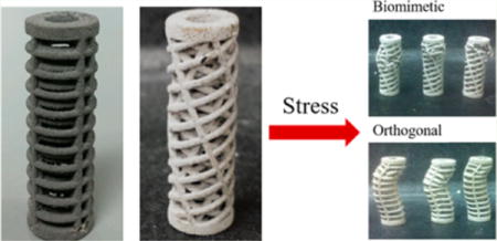
Additive manufacturing presents opportunities to treat bone defects using biomimetic tissue scaffolds. Past investigations have explored modulating scaffold mechanical properties through varying materials and geometric motifs. Herein, we applied the rotated plywood structure of bone tissue to a 3D printed scaffold with the goal of improving mechanical performance compared to an orthogonal mesh design commonly used in tissue scaffold applications. The scaffolds were subjected to uniaxial compression followed by scanning electron microscopy and microcomputer tomography. The uniaxial compression test was characterized through elastic modulus (mean 1.32 GPa biomimetic, 0.196 GPa orthogonal, p < 0.001), ultimate compressive strength (mean 16.546 MPa biomimetic, 6.309 MPa orthogonal design, p < 0.001), and ultimate compressive strain values (4.867% biomimetic, 9.000% orthogonal, p < 0.005). Correlation of microfracture imaging to bulk scaffold mode of failure suggest that utilizing the biomimetic plywood design not only improved mechanical performance, but also reduced asymmetrtic buckling, plastic deformation, and fracture propagation similar to bone tissue.
Keywords: biomimetic, scaffold, tissue engineering, plywood, 3D printing
Graphical abstract
1. INTRODUCTION
Treatment of critical sized bone defects resulting from traumatic fractures through a space-filling, load-bearing bone graft substitute is an area of increasing interest in the development of orthopedic implants.1–3 Traditional methods of treatment through autologous or allogenic bone grafts, while fulfilling criteria of osteoconductivity (surface biocompatibility for growth of bone tissue) and osteoinductivity (recruitment and stimulation of immature cells into preosteoblasts), feature risks of complications and are highly invasive, which may be addressed through the synthesis and design of synthetic bone scaffolds.4
Solid free-form fabrication (SFF) approaches to porous bone scaffolds have garnered much attention in recent months because of their convincing and proven demonstration of capabilities to produce complex 3D structures generated from patient imaging modalities and computer-assisted design (CAD) models.5–8 More specifically, the binder-jetting 3D printing (3-DP) method selectively deposits a liquid binder solution onto a spread powder bed to construct a CAD model on a layer-by-layer basis. This technique features the versatility in materials composition using the ability to accommodate a wide range of powders and binder formulations, including metal alloys relevant to load-bearing orthopedic and craniofacial implants such as titanium and titanium alloys, Fe-based alloys including novel Fe-based alloy compositions developed in our lab and elsewhere have indicated promise of undergoing resorption under physiological conditions.9–14
The impact of structural design on mechanical performance of SFF scaffolds has been an investigative subject of increasing interest in the field of materials science. Especially relevant to the field of orthopedic implant design, titanium and titanium alloy scaffolds have been fabricated in geometric matrix designs prior to mechanical investigations. Although past investigations have been successful in demonstrating significant differences in mechanical performance in relation to scaffold design, replication of complex behaviors of native tissue through biomimetic design is a direction requiring further study.15,16 Similarly, bioceramic and polymer composite scaffolds have also been explored for structure–performance relationships, but most fabricated scaffold designs remain relatively unsophisticated in terms of the geometric organization and their relationship to both mechanical and potential physiological performance.17–19 Previous investigations have commonly relied upon a standardized orthogonal porous mesh design for simplicity in exploring compositional variations. However, in this study, a focus will be placed on the significance of biomimetic structural design.20,21
Although mechanical performance has been one of the primary driving factor in the exploration of material alternatives for orthopedic load-bearing SFF applications, several studies have emphasized the significance of structural organization on mechanical performance in natural bone tissue.22–26 The concept of biomimetic design itself has been explored on a variety of size regimes for bone tissue engineering (BTE) given the hierarchical nature of bone structure.27–32 However, the translation of bioinspired structural motifs to SFF exploiting the advantage of 3-DP fabrication in creating complex architectures may expand our control over modulation of mechanical performance through specialized design incorporating stress-adapted behaviors of natural bone tissue.
Recent studies have suggested a prominent motif of lamellar plywood organization in natural bone tissue, where subsequent layers of parallel mineral-embedded microfibers are rotated to create an overall spiral twist, which then organize into cylindrical units referred to as osteons.33 Mechanical properties, including extensibility, flexibility, load-bearing, and energy-dissipating capacity against fracture crack propagation, are derived from variations in the microfiber lamellar angle of this plywood motif, and are highly relevant to the design and performance of a functional biomimetic orthopedic scaffold, which may also affect the extent of cellular infiltration during the tissue regenerative process.34
Utilizing binder-jet 3-DP, we aim to explore the structure-based variations in mechanical performance of a simplified cylindrical lamellar scaffold featuring a biomimetic rotated plywood organization, with accompanying material and biological characterization. Although this design is a simplification of the complex periodic structure of natural bone tissue, it offers a new level of biomimetic complexity in the design and demonstrates the fabrication capacities of binder-jet 3-DP in comparison against current structural designs in SFF literature designed primarily for prototyping of materials development.35–38
Mechanical performance of similar fiber-reinforced composite materials has previously been evaluated through analysis of stress–strain performance, crushing modes, and their associated crushing mechanisms which contribute to the overall structural failure under compressive loading.39–41 Although ply orientation has previously been implicated in composite energy absorption, we seek to relate this previous insight into bone tissue engineering through investigation of mechanical performance of a complex biomimetic structure. At the same, the objective will be to maintain previously established fundamentals of mechanical and crushing analysis while applying it to the area of bone modeling and regeneration.42,43 A secondary aim of this study is to investigate the causes of possible underlying structure-associated trends of failure mechanisms primarily applying imaging analyses employing scanning electron microscopy (SEM) as well as microcomputed tomography (μCT) analysis exploiting quantitative and qualitative modes to garner predictive concepts related to bone regeneration.
This structure-centered approach introduced herein may also provide insight toward development of 3D printed orthopedic implants in a variety of material contexts. Understanding of complex fibrous scaffold behaviors in failure and retaining natural bone biomechanics in a load-bearing application may contribute toward the large-scale bone defect repair of considerable relevance to civilian and military related traumatic injuries.
2. MATERIALS AND METHODS
2.1. Scaffold Design
Two scaffold designs were generated using Autodesk Inventor software featuring lamellar strut orientation variations on a hollow cylinder design. Height and diameter of the samples were 36.0 and 12.0 mm respectively, with an inner diameter of 6.0 mm. Both designs exhibited three nested concentric lamellae of orthogonal mesh pattern struts with circular cross-section of diameter 1.0 mm for a total layer thickness of 3.0 mm. Vertical and horizontal distance between struts for both scaffold designs are exhibited in Table 1 for each lamellae.
Table 1.
Measured Distances between Struts Controlled in Both Alternating and Orthogonal Scaffold Designs for Concentric Scaffold Lamellae
| layer | longitudinal distance (mm) | transverse distance (mm) |
|---|---|---|
| innermost | 4.07 | 0.91 |
| middle | 2 | 5.41 |
| outermost | 2.24 | 7 |
For the “orthogonal” scaffold design, orthogonal lamellae were oriented along the cylindrical longitudinal axis and transverse planes. Longitudinal and transverse struts were aligned in the radial outward direction to mimic the straight porous channels implemented in previous SFF scaffold designs. For the “alternating” scaffold featuring the biomimetic rotated plywood structural motif, quantitative lamellar angular rotation data was extracted from previous structural elucidation of secondary human bone osteons carried out using X-ray microdiffraction.33 Because of the constraints of the fabrication process, a representative section of the total quantitative microdiffraction structural data was used in scaffold design to accommodate for simplification of 3 lamellae in a hollow cylindrical model for angular rotations of 68, 25, and 80° off the longitudinal axis, from the outermost lamellae inward. These scaffold designs are exhibited in Figure 1a, b. Additional images and characterization of dimensions are given in Figures S1–S3.
Figure 1.
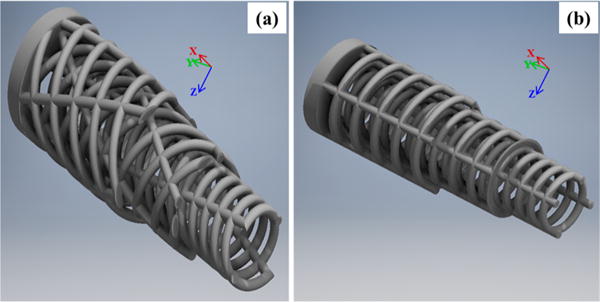
CAD 3D rendering of (a) alternating design featuring rotated plywood motif for strut lamellae. Outer two layers have been transversely sectioned to reveal internal architecture; (b) orthogonal mesh design. Each strut lamella features same strut dimensions, transverse, and longitudinal interstrut distance as alternating design. Outer two layers have been transversely sectioned to reveal internal architecture.
Based on the CAD data, scaffolds (n = 13 for each design) were fabricated by means of a binder-jetting 3D printing process (The ExOne Company, LLC, North Huntingdon, PA) from iron (Fe) powder with average particle size of ~45 μm (99%, Höganäs AB, Höganäs, Sweden). Printed green constructs were cured at 195 °C for 1 h to improve part stability, then depowdered using pressurized air and sintered at 1100 °C for 3 h to remove the binder and densify the parts.
2.2. Scaffold Physical Properties
Porosity values for scaffolds were calculated according to both CAD engineered porosity and fabrication introduced porosity (in binder-jetting 3D printing, curing, and sintering processes). Engineered CAD porosity (ρCAD) was calculated according to the following equation
| (1) |
Where Vsc is the total volume of the CAD scaffold design and Vcyl is the overall volume of the theoretical hollow cylinder enclosed by the outer and inner peripheries of the CAD scaffold design.
Unsintered (ρUS) and sintered (ρS) porosities represented deviation in scaffold material density compared against a theoretical density of pure iron and do not include engineered CAD porosity of overall scaffold designs. These were calculated according to the following equation
| (2) |
Where ρFe is the density of nonporous iron (7.874 g/cm3) and ρsc is the density of the manufactured scaffolds (before or after sintering), calculated using the weight and volume of the scaffolds (n = 3 for orthogonal, n = 2 for alternating, unpaired).
2.3. Mechanical Testing
Compressive testing was conducted in accordance with ASTM-E9. Uniaxial compressive testing was performed with sintered scaffolds at room temperature with an Instron 5566 mechanical testing system (Instron, Norwood, MA) using a cross-head speed of 3 mm/min and a 5 kN load cell. Ultimate compressive strength, Young’s modulus, and strain (percent elongation) at failure were determined from stress–strain curves generated from each specimen. Young’s modulus was obtained as the slope of linear regression over the elastic performance region of each stress–strain curve. Ultimate compressive strength and strain at failure were determined as the maximum compressive stress and corresponding strain. Average, standard deviations, and one-way independent ANOVA results for both scaffold designs (n = 8 for each design) are reported.
2.4. Scanning Electron Microscopy
Scanning electron microscopy (SEM) images were also taken of sintered scaffolds before and after uniaxial compressive testing using a Philips-XL30 FEG (Philips, Amsterdam, The Netherlands) at 10.0 kV at various magnifications for surface fracture analysis.
2.5. Microcomputed Tomography (μCT)
Scaffold specimens (n = 3 for each design) were scanned with a VivaCT40 (Scanco Medical AG, Bruttisellen, Switzerland) and 30 μm voxel size (70 kV, 110 μA). For analysis, scanned scaffold volumes were digitally reoriented, filtered from background signal, and converted to.stl format for standardized quantitative analysis using Mimics Medical 17.0 (Materialise NV, Leuven, Belgium). For directionality analysis of different modes of failure between scaffold designs, outward deformation measurements in radial step size of 30 degrees were taken at transverse slices of 5 mm step size for each scanned specimen, and plotted as a deformation profile illustrating significant variations in radial direction of deformation.
3. RESULTS
3.1. Scaffold Porosity
Calculated porosities, total surface area, and average cross sectional surface area for CAD scaffold designs and fabricated samples are listed in Table 2. Both scaffold designs exhibited an engineered porosity of approximately 53–54%, while additional porosity in the 3-DP fabrication process was introduced at approximately 15% for all the unsintered specimens. After sintering, the material porosity decreased for both scaffold designs to approximately 8% for orthogonal specimens (n = 6) and 14% for alternating specimens (n = 4). Variations in porosity introduced through the fabrication process was less than 5%. Total surface area for both scaffold designs was approximately 46 cm2, whereas scaffold volumes were calculated to be 1.436 cm3 for the orthogonal design and 1.407 cm3 for the alternating design. Greater variation was seen in the average calculated scaffold cross-section area, with 0.4047 cm2 for the orthogonal design and 0.2087 cm2 for the alternating design.
Table 2.
Porosities Calculated from CAD and for Fabricated Specimens Given As Mean ± Standard Deviation, Total Surface Areas, and Average Cross-Section (CS) Areas Calculated from CAD
| porosity
|
||||||
|---|---|---|---|---|---|---|
| design | CAD (%) | unsintered (%) | sintered (%) | surface area (cm2) | volume (cm3) | average CS area (cm2) |
| orthogonal | 53 | 15.5 ± 2.5 | 8.1 ± 3.3 | 46.71 | 1.436 | 0.4047 |
| alternating | 54 | 15.2 ± 3.1 | 14.3 ± 2.3 | 45.62 | 1.407 | 0.2087 |
3.2. Mechanical Behavior
Stress–strain relationships plotted in Figure 2 were calculated using values for average cross sectional area for respective scaffold designs. The stress primarily reflected force acting upon the overall scaffold structure and does not represent stress within the individual struts.
Figure 2.
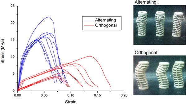
Engineering stress–strain relationships for all scaffold specimens. Photographs of representative specimens after mechanical failure are shown to the right.
Significant variation is illustrated in the stress–strain plots for all compressed samples between the two scaffold designs (n = 8 each). Orthogonal and alternating specimens varied in slope of stress against strain immediately following start of compression in the elastic performance region (shown in Figure 3). Orthogonal design specimens demonstrate a distinct transition from elastic to plastic performance in change of slope with positive linear trends for both regimes. Alternating design specimens demonstrate no discrete change in slope from start of compression to peak load at failure. Performance is instead characterized by a gradual, curved trend. Scaffold performance after failure for alternating design specimens was characterized by interruptions in decreasing trend after peak load, whereas orthogonal designs featured smooth decreases in stress–strain relationships.
Figure 3.
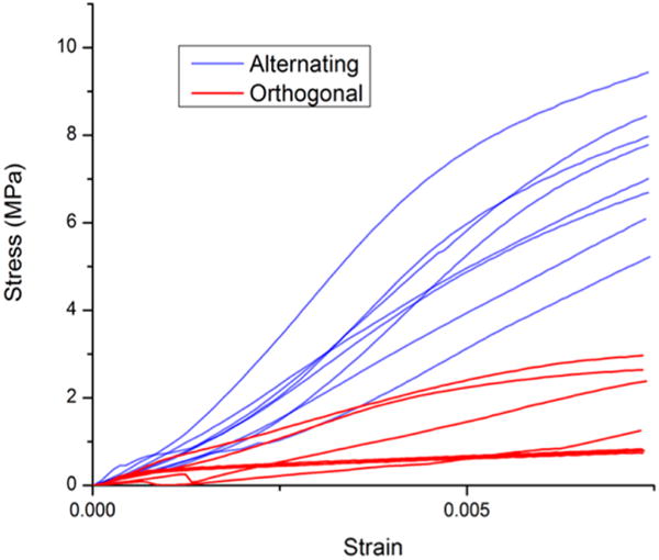
Engineering stress–strain relationships for all scaffolds abridged to specific data ranges for elastic performance regimes. Elastic moduli were calculated using slopes of linear regressions for positive linear trends.
Scaffold mechanical properties shown in Table 3 were derived from stress–strain relationships plotted in Figure 2. The elastic modulus was calculated using linear regression of the region of elastic response (Figure 3). Ultimate compressive strength was defined as the peak stress measured before scaffold failure. Ultimate compressive strain was defined as the strain corresponding to ultimate compressive strength. Values in Table 3 are plotted in Figure 4a, b, and c in the form of means (n = 8 for each scaffold design). Alternating scaffolds featured higher elastic modulus (p < 0.0001), higher ultimate compressive strength (p < 0.0001), and lower strain at failure (p < 0.0004).
Table 3.
Scaffold Specimen Mechanical Properties, Given As Mean ± Standard Deviationa
| scaffold design | elastic modulus (GPa) | ultimate compressive strength (MPa) | ultimate compressive strain (%) |
|---|---|---|---|
| orthogonal | 0.196 ± 0.158 | 6.309 ± 2.308 | 9 ± 2.243 |
| alternating | 1.320 ± 0.369 | 16.546 ± 2.292 | 4.867 ± 1.017 |
N = 8 for each scaffold design.
Figure 4.
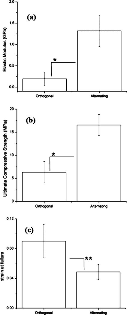
Values for (a) elastic moduli, (b) ultimate compressive strength, and (c) strain at failure for orthogonal and alternating scaffold designs. Bars represent means with error bars indicating standard deviation. Significance (* p < 0.001 and ** p < 0.004) analyzed using one-way independent ANOVA (n = 8 for each design).
3.3. SEM Analysis
The morphologies of both 3-DP scaffold types are shown in Figure 5 before uniaxial compressive testing. No significant variations in particle size, extent of sintered porosity, or microstructure were observed. Qualitative surface analysis shows a porous topography confirming previous applications of 3-DP scaffold applications, although printed scaffolds were not surface finished and no significant oxide layer was observed.
Figure 5.
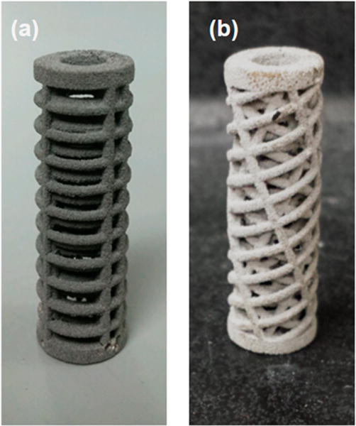
(a) Orthogonal design scaffold after fabrication and postprocessing. (b) Alternating (biomimetic plywood) design scaffold after fabrication and postprocessing.
Figures 6 and 7 show failure characterization for both types of 3-DP scaffolds through microfracture analysis. Figure 6a, b illustrate typical fracture propagation through alternating design specimens. Both intralamellar and interlamellar fractures varied in orientation with respect to the longitudinal axis (indicated by red line), and depth on the transverse plane. Scaffold struts were also shown to fracture at different locations respective to intralamellar strut junctions. This mode of highly disorganized and deflected fracture propagation was consistent across the entire scaffold surface area in regions of failure for all the alternating design specimens, in contrast against orthogonal design specimens, as represented in Figure 6c, d. Failure microfractures, while misaligned in alternating design specimens across a range of angular orientations, showed a high level of organization in both longitudinal and transverse directions in orthogonal design specimens (longitudinal axis indicated in red) and affecting multiple strut lamellae. Occurring at the same angular orientation and location with respect to lamellar strut junctions, propagated fractures of greater continuous length and cross-sectional area were observed in orthogonal design scaffolds.
Figure 6.
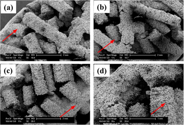
SEM imaging of representative scaffolds after compression showing varying patterns of strut failure. Parts a and b represent alternating scaffolds demonstrating varying directions of fracture propagation, whereas c and d represent orthogonal scaffolds demonstrating linear continuous fracture propagation. Red arrows indicate direction of scaffold longitudinal axis.
Figure 7.
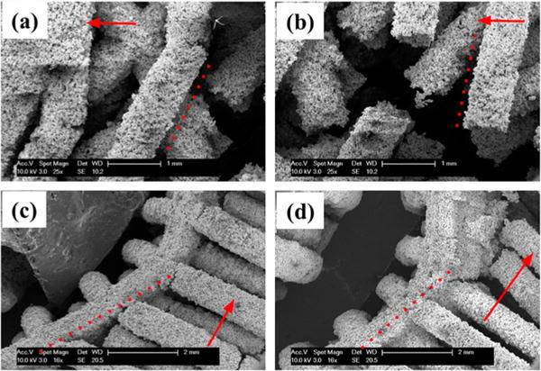
SEM imaging of representative scaffolds after compression. Dashed lines indicate original strut direction before compression and red arrows indicate scaffold longitudinal axis. Parts a and b represent alternating scaffolds showing little to no strut plastic deformation seen in similarity of alignment to the dashed red line. Parts c and d representing orthogonal scaffolds show significant asymmetric plastic deformation after compression seen in the curved deflection of the scaffold away from the dashed red line.
Figure 7 shows distinctions in individual strut performance before failure between the two scaffold designs. Struts in alternating design specimens underwent minimal plastic deformation before brittle fracture as shown in Figure 7a, b. Although microfracture initiation is apparent in Figure 7a, struts of both alternating directions remained generally unbent before failure (marked by dotted line), a trend reflected in fractured struts as in Figure 7b, where fractured strut ends were also observed to have undergone little plastic deformation. This is contrasted in orthogonal design specimens as shown in Figure 7c, d, where extensive asymmetrical plastic deformation can be observed in the vertical struts (in deviation from dotted line). Plastic deformation occurred prior to strut fracture as illustrated in Figure 7c in orthogonal design specimens, where fracture propagation has not yet fully occurred through the horizontally oriented struts (longitudinal axis indicated by arrow), whereas Figure 7d shows the aftermath of complete strut fracture after significant plastic deformation. Regions of greatest plastic deformation corresponded to asymmetrical buckling in scaffold overall structure, and were observed adjacent (nearest strut junction) to the large, continuous fractures noted in Figure 7c in accordance with the failure mode seen in Figure 6c. Additional SEM images are shown in Figure S4.
3.4. μCT Analysis
3D renderings of representative scanned scaffolds are exhibited in Figure 8 and show distinct trends of deformation behavior resulting from compressive loading. Orthogonal design specimens featured severe asymmetric buckling and plastic deformation of longitudinal struts before extensive continuous fracture propagation through transverse struts parallel to the scaffold longitudinal axis. Radial position of these multistrut fractures commonly occurred orthogonally to the direction of plastic buckling. This failure mode characteristic of orthogonal design scaffolds was reflected in the deformation profile in Figure 9. Especially evident as transverse graphs progress toward the scaffold middle section, deformation distance followed a negative trend under approximately 150° and an increasing trend over approximately 150°. Deformation trend took on an increasingly sinusoidal appearance characteristic of circular linear translation. A buckling radial direction typical of orthogonal design specimens can be identified as the angular position of the peak maximum in the 10 mm deformation graph. Opposite to this direction, the specimen wall featured inward deformation following the pattern of outward deformation exemplifying plastic buckling behavior.
Figure 8.
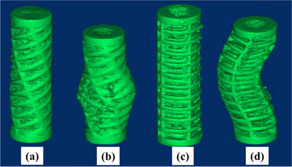
3D rendered micro-CT images for representative scaffold specimens. a–d represents alternating before compression, alternating after compression, orthogonal before compression, and orthogonal after compression, respectively.
Figure 9.
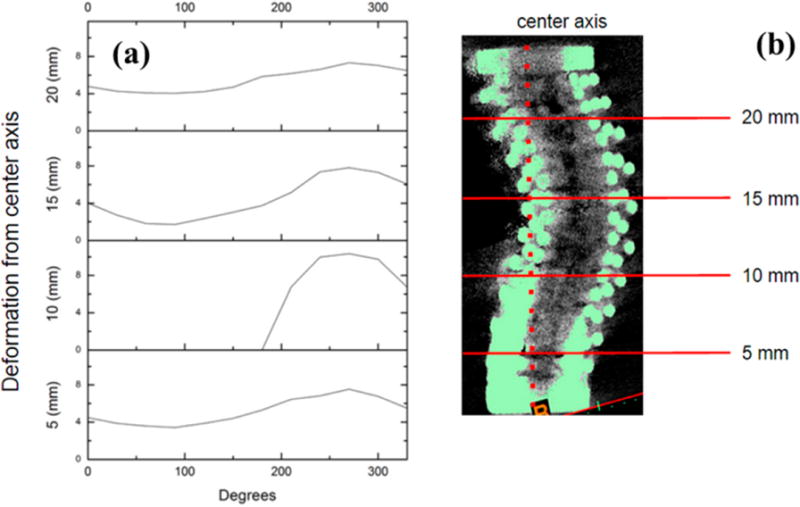
(a) Deformation profile of an orthogonal design specimen. (b) Transverse section graphs against radial position correspond to marked locations on μCT image to the right with deformation calculated against indicated center axis.
In contrast, deformation trends typical for alternating design specimens plotted on same axes scales show a significant decrease in variability for all transverse sections as exhibited in Figure 10. There remains a similar increasing trend in deformation distance as sections approach the region of failure. However, deformation distance did not depend on radial position, and no apparent maximum could be identified as in deformation trends of orthogonal design scaffolds. This distinct mode of failure deformation was apparent in the 3D rendering in Figure 8 as a general radial outward crumpling of the scaffold wall. Plastic deformation was much less severe compared to orthogonal design scaffolds, with homogeneous distribution of smaller single-strut fractures over the entire surface of the failure region. No regions of inward deformation were identified for any alternating design specimens.
Figure 10.
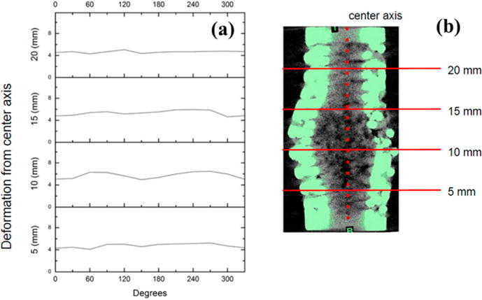
(a). Deformation profile of an alternating design specimen. (b). Transverse section graphs against radial position correspond to marked locations on μCT image to the right with deformation calculated against indicated center axis.
4. DISCUSSION
The purpose of this study was to investigate changes in 3D fabricated scaffold mechanical performance arising solely from variation in the structural geometry using the biomimetic lamellar rotated plywood structural motif. Although previous investigations have also sought to demonstrate relationships between the structure and mechanical performance, our aim in applying the biomimetic approach to scaffolds for bone was to possibly replicate certain specialized behaviors of natural tissue in scaffold performance while demonstrating significant changes in the scaffold mechanical properties.40,44 Although matching the mechanical properties of bone tissue remains a future endeavor, another aim of this investigation was to demonstrate that other distinctions in performance, such as mode of failure, fracture propagation, and extent of plastic deformation, may also arise from variation in structural organization and may be significant for future tissue engineering implant applications.
Fabrication of complex scaffold designs with internal architectures was made possible through use of SFF binder-jetting printing techniques following printing to generate the green constructs followed by sintering. Another goal of this study was to determine the specific mechanistic origins of variations in mechanical performance for these different architectures. Other methods of additive manufacturing have recently gained popularity, such as laser or electron beam melting, and have seen relative success in producing similar strengths against cast and wrought samples as well.45,46 Investigation of structural impact on performance, being independent to material composition or mode of fabrication, may be easily adapted to these other methods of additive manufacturing.
In this study, statistical analyses performed on mechanical properties extracted from the stress–strain relationships for the orthogonal and alternating scaffold designs revealed significant variation in elastic modulus, ultimate compressive strength, and ultimate compressive strain, with alternating design specimens being higher in the first two and lower in the last. One possible contributing factor to these variations in performance is the significantly lower cross sectional area for the alternating scaffold design as exhibited in Table 2. This was likely the result of geometric lamellar orientation, as the total scaffold volume, surface area, and engineered porosity were relatively similar between the two designs. These similarities support claims of structural orientation significance by controlling for other design differences between the two scaffold types (aside from sintered scaffold porosity). Because the alternating scaffold lamellae were rotated with respect to the scaffold longitudinal axis, equivalent transverse struts also shared complementary rotation, resulting in no struts lying parallel to the scaffold transverse plane and adding significant contribution to average cross sectional area. This was not the case in the orthogonal scaffold design, as transverse fibers contributed full fiber longitudinal cross section area to the average scaffold cross section area at those transverse ranges, resulting in approximately twice the overall scaffold average cross sectional area compared against the alternating design. Ultimate compressive strength differences reflected this as well, being on average 6.309 MPa for orthogonal specimens and 16.546 MPa for alternating specimens (Table 3). However, the levels of load before conversion to stress for alternating scaffolds were still higher than orthogonal scaffolds, having more than twice the ultimate compressive strength.
To further investigate load-bearing differences between volumetrically similar scaffolds, finer analysis using SEM imaging contributes largely to the mechanistic fracture information. It was previously established that alternating specimens featured brittle strut fractures with no observable strut plastic deformation, whereas orthogonal specimens featured significant plastic deformation before undergoing eventual fracture of neighboring transverse struts. These differences in fracture mechanisms may also have been a result of variations in the geometric orientation of struts relative to the axis of applied loading. Plastic deformation, or buckling, is a common phenomenon of longitudinal axial compressive loading.42,47 However, alternating designs featured no strut longitudinal axial loading. Instead, all the stress was applied under an angular shear regime, resulting in brittle fracture with transverse fracture surfaces typical of metal specimens.48–50 On a macroscopic scale, these mechanistic differences resulted in a general “crumpling” for alternating designs as shown in Figures 8 and 10, wherein the failure was evenly distributed in the radial direction by strut fracture, whereas the large plastic deformation characteristic of orthogonal designs led to an overall “buckling” of the specimens as revealed by the deformation profile maps corresponding to the transverse μCT scan in Figures 8 and 9, respectively. These variations in the performance not only affected the scaffold mechanical properties, but also contributed to significant distinctions in the overall structure failure performance. General effects of these distinctions were characterized through the scaffold deformation profiles quantifying μCT 3D scans shown in Figures 8–10. Buckling of orthogonal specimens can clearly be compared against crumpling of the alternating strut design specimens by observing changes in deformation over radial position for transverse sections over the length of the specimens. This is further evidence of the clear variation in failure performance for the two scaffold designs.
Previous investigation of failure mode fundamentals in fiber-reinforced composites (extrapolated to the fibrous lamellae organization of scaffold designs featured in this investigation) established classification of fracture behaviors into distinct categories of transverse shear, lamina bending, and local buckling under compressive loading. In consideration of the fracture behaviors exhibited by SEM images (Figure 7), we may translate distinct behaviors of alternating and orthogonal struts into these terms. In observation of fracture edges, interlaminar, and longitudinal cracks in partial lamina bundles demonstrated by alternating specimens, the mode of failure of this scaffold design may be classified as the transverse shearing crushing mode described by Farley and Jones.51 In orthogonal specimens, SEM results exhibit severe lamina bending, while interlaminar parallel-to-fiber cracks propagate within several adjacent laminae, whereas other lamina bundles exhibit significant plastic bending deformation before fracture. These behaviors result in the categorization of orthogonal scaffold design failure in the lamina bending crushing mode as described by Farley and Jones.51 These results thus contribute to our understanding of sustained scaffold crushing stress as a function of ply angle. In the context of a load-bearing, bone tissue engineering application, these variations in failure performance may be significant in changing the scaffold interaction with the tissue–scaffold interface. Given the importance of surface contact in physiological regenerative processes including cell infiltration and surface remodeling, and applied stress in stimulating osteocyte activity, radial and longitudinal profiling of deformation under compressive loading for this study’s cylindrical model illustrates the significance of geometric design.43,52,53 In consideration of the current geometric designs common to the field of SFF additive manufactured scaffolds, asymmetric plastic buckling of the orthogonal design featured in this study illustrates potential negative impacts upon the physiological interface. Although it is acknowledged that compressive loading was performed in a free-standing context, and that future implant applications in a fully tissue-embedded context may result in different deformation behavior because of stress transference to surrounding tissue, it remains that excessive asymmetric stress transference and tissue stimulation may be inferior to symmetric performance given the goal of bone tissue engineering to reproduce the loading environment of native tissue.54,55 We assert that for larger scales of bone tissue engineering, especially in a heavier load-bearing context akin to normal bone functioning, the alternating biomimetic design presented in this study offers superior performance in failure suitable for sustained biological interfacing.
Observing the SEM images presented in Figure 6 offers additional insight into possible biomimetic mechanical behavior arising from the biomimetic structural design for alternating specimens. Fibrous lamellae of bone tissue are known to contribute to mechanical performance through crack bridging and fracture deflection, where microscopic structures assist in preventing exacerbation of tissue defects.56,57 A similar phenomenon was observed in the alternating biomimetic design shown in Figure 6a and 6b, where fractures were highly varied in length and angle compared to the extensive, linear fractures observed in the orthogonal design seen in Figure 6c, d. We propose that this behavior is a macroscopic scaling of crack bridging and fracture deflection behaviors observed in microscopic iterations of this lamellar rotated plywood structure, in that larger, continuous fractures were hindered in formation by the alternating design and varying strut orientation between different lamellae as well in adjacent struts within the same lamella. This presentation resulted in the presentation of a more homogeneous fractured outer surface texture, as well as contribution toward radially symmetric failure performance. Large, extensive fractures in orthogonal specimens were also correlated with severe plastic deformation in neighboring longitudinal struts, with both being characteristic of asymmetric failure performance.
Another notable characteristic of alternating specimen stress–strain relationships was the lack of a distinction between elastic and plastic regions of deformation. As exhibited in Figure 5, the graduated, sloping curvatures of alternating trends translates to more homogeneous behavior under compression than that of orthogonal specimens which featured two distinct regions of elastic and plastic mechanical behavior. Smooth compressive behavior may be a significant contributor to replicating organic phase contributions to bone tissue behavior, given the composition of bone tissue featuring collagen fibers that inherently behave more similarly to a viscoelastic tissue model than stress–strain behavior of metal alloys.
In all, this study was successful in demonstrating significant changes in the mechanical performance for the biomimetic variation in scaffold design with one-way independent ANOVA p-values less than 0.001 for elastic modulus, ultimate compressive strength, and less than 0.004 for strain at failure (Figure 4). Aside from mechanical parameters of performance, qualitative and quantitative analysis of failure mode and deformation also showed distinct behaviors of the two scaffold designs. Given the isolated variable of geometric design, we aim to apply a similar principle to future investigations featuring scaffold material compositions more widely accepted as standards for orthopedic implantation applications, namely titanium and its alloys. Verification of similar significant implications of structural variation in a greater variety of materials will generate stronger support for the possibility of fine-tuning structural design for mechanical performance in specific load-bearing contexts. The biomimetic design utilized in this study was generated from previous experimental data taken from human bone samples. Full complexity of elucidated native tissue structure may be more fully represented through more extensive design and fabrication for structures featuring higher numbers of lamellar angular periodic repetitions, as well as internal channel microstructure for more faithful replication of osteonal and vascular structures in bone likely requiring configurations with varying ply angle in line with Figures 8 and 9 discussed above replicating higher orders of tissue–bone interface interactions as also shown in Figures S1 and S2. Such configurations will likely help in achieving mechanical characteristics similar to what is seen in human bone tissues thus, offering new directions in scaffold design using additive manufacturing.
Aside from mechanical performance parameters, other behaviors exhibited by the rotated plywood design suggested possibility of scaling up microscopic organic tissue phenomenon in response to mechanical stimulation that may offer previously unconsidered benefits on a macroscopic scaffold level. Additional loading regimes including shear and flexure may warrant further investigation given the complex loading environment of native bone tissue and orthopedic implants upon clinical implementation. However, from the investigations performed, we believe that the rotated plywood design in tissue engineering applications may offer significant improvement to mechanical performance on existing SFF additive manufacturing designs, and may also contribute to future macroscopic space-filling, load-bearing applications for synthetic bone tissue replacements. Given the necessity of introducing tissuelike behaviors on a macroscopic level to nonorganic implants and scaffolds, the concept of biomimetic design inspired from complex hierarchical structures of bone tissue may provide a pathway to improve the compatibility of implant and scaffold performance beyond numeric parameter considerations, but also in more complex, structural geometry influenced behaviors such as compressive deformation, stress distribution, and fracture propagation. We believe this research to be especially compatible with many current investigations on various material compositions for orthopedic implants given the independence of scaffold structural design to structural composition, and that insights derived from the structural biomimetic design may be applied and hold true for a variety of materials, calling for further investigation. The design considerations observed and explained herein may provide novel approaches to the fabrication and manufacturing of high strength scaffolds as well as implants for load-bearing large critical-sized segmental bone defects, for which there are no current scaffold strategies. The approach can thus offer a unique solution for both existing traditional nondegradable implant systems such as stainless steel, titanium and titanium alloys including Co–Cr alloys as well as the new and evolving degradable magnesium and magnesium alloy-based metallic systems particularly, for load-bearing orthopedic and craniofacial applications.
5. CONCLUSIONS
Using binder-jetting 3D SFF fabrication, biomimetic structural motifs may be implemented in load-bearing, lamellar, porous bone scaffolds to replicate and scale up complex hierarchical mechanical responses observed in natural tissues. Utilizing the rotated plywood design, deformation and buckling under compressive loading may be distributed evenly in the radial direction for superior interface with the surrounding physiological microenvironment in the context of implantation. Distinct changes in mechanical performance from the elastic to plastic deformation regime transition may also be reduced and smoothed to a single regime as another result of crumpling scaffold behavior introduced by the rotated plywood design. Mechanical performance parameters (including ultimate compressive strength and elastic modulus) may be greatly enhanced for rotated plywood design scaffolds of approximately similar bulk scaffold volume and porosity of compared against a standardized geometric mesh design. Implementation of a biomimetic rotated plywood design also introduced semblances of fracture crack deflection behavior between and within scaffold lamellae, also serving to homogenize the stress distribution away from asymmetries of stress concentration found in the orthogonal mesh design likely mimicking the mechanical characteristics of the tissue–bone interface. Control for structural effects on mechanical performance suggests further validation of design significance is possible for a wider range of scaffold materials. Quantitative variation on biomimetic design parameters for more specific control over aspects of mechanical performance remains an area of future investigation with the goal of creating scaffolds customized for specific stress–response behaviors in various dynamic loading regimes.
Supplementary Material
Acknowledgments
The authors gratefully acknowledge the financial support of America Makes, Grant FA86650-12-2-7230. The authors also express their profound gratitude to the financial assistance provided by the U.S. National Science Foundation, Engineering Research Center, Grant EEC-0812348 for providing the metallurgical and printing related resources. Additionally, G.Z.Y. is thankful to the NIH training grant T32-GM008208-27 (NIGMS) for supporting the support needed during the entire period of the study. PNK would also like to acknowledge the Edward R. Weidlein Chair Professorship as well as the Center for Complex Engineered Multifunctional Materials (CCEMM) for partial support of the research. Finally, Maria J. Ly is acknowledged for her assistance in editing the manuscript.
Footnotes
Supporting Information
The Supporting Information is available free of charge on the ACS Publications website at DOI: 10.1021/acsbiomaterials.7b00043.
Layer-by-layer view of alternating rotated plywood scaffold design; side view of alternating scaffold design; layer-by-layer view of orthogonal rotated plywood scaffold design; additional representative SEM images of both orthogonal and alternating scaffolds (PDF)
ORCID
Prashant N. Kumta: 0000-0003-1227-1249
Notes
The authors declare no competing financial interest.
References
- 1.Schmitz JP, Hollinger JO. the Critical Size Defect As an Experimental-Model for Craniomandibulofacial Nonunions. Clin Orthop Relat Res. 1986;(205):299–308. [PubMed] [Google Scholar]
- 2.Praemer A, Furner S, Rice DP. Musculoskeletal Conditions in the United States. American Academy of Orthopaedic Surgeons; Rosemont, IL: 1999. [Google Scholar]
- 3.Olivier V, Faucheux N, Hardouin P. Biomaterial challenges and approaches to stem cell use in bone reconstructive surgery. Drug Discovery Today. 2004;9(18):803–811. doi: 10.1016/S1359-6446(04)03222-2. [DOI] [PubMed] [Google Scholar]
- 4.Albrektsson T, Johansson C. Osteoinduction, osteoconduction and osseointegration. Eur Spine J. 2001;10:S96–S101. doi: 10.1007/s005860100282. [DOI] [PMC free article] [PubMed] [Google Scholar]
- 5.Hollister SJ. Porous scaffold design for tissue engineering. Nat Mater. 2005;4(7):518–524. doi: 10.1038/nmat1421. [DOI] [PubMed] [Google Scholar]
- 6.Rengier F, Mehndiratta A, von Tengg-Kobligk H, Zechmann CM, Unterhinninghofen R, Kauczor HU, Giesel FL. 3D printing based on imaging data: review of medical applications. International Journal of Computer Assisted Radiology and Surgery. 2010;5(4):335–341. doi: 10.1007/s11548-010-0476-x. [DOI] [PubMed] [Google Scholar]
- 7.Sun W, Starly B, Nam J, Darling A. Bio-CAD modeling and its applications in computer-aided tissue engineering. Computer-Aided Design. 2005;37(11):1097–1114. [Google Scholar]
- 8.Murr LE, Quinones SA, Gaytan SM, Lopez MI, Rodela A, Martinez EY, Hernandez DH, Martinez E, Medina F, Wicker RB. Microstructure and mechanical behavior of Ti-6Al-4V produced by rapid-layer manufacturing, for biomedical applications. Journal of the Mechanical Behavior of Biomedical Materials. 2009;2(1):20–32. doi: 10.1016/j.jmbbm.2008.05.004. [DOI] [PubMed] [Google Scholar]
- 9.Sachs E, Cima M, Cornie J. Three-Dimensional Printing: Rapid Tooling and Prototypes Directly from a CAD Model. CIRP Ann. 1990;39(1):201–204. [Google Scholar]
- 10.Butscher A, Bohner M, Hofmann S, Gauckler L, Muller R. Structural and material approaches to bone tissue engineering in powder-based three-dimensional printing. Acta Biomater. 2011;7(3):907–920. doi: 10.1016/j.actbio.2010.09.039. [DOI] [PubMed] [Google Scholar]
- 11.Sachs E, Wylonis E, Allen S, Cima M, Guo HL. Production of injection molding tooling with conformal cooling channels using the three dimensional printing process. Polym Eng Sci. 2000;40(5):1232–1247. [Google Scholar]
- 12.Wiria FE, Shyan JYM, Lim PN, Wen FGC, Yeo JF, Cao T. Printing of Titanium implant prototype. Mater Eng. 2010;31:S101–S105. [Google Scholar]
- 13.Hermawan H, Moravej M, Dubé D, Fiset M, Mantovani D. Degradation Behaviour of Metallic Biomaterials for Degradable Stents. Adv Mater Res. 2007;15–17:113–118. [Google Scholar]
- 14.Hong DH, Chou DT, Velikokhatnyi OI, Roy A, Lee B, Swink I, Issaev I, Kuhn HA, Kumta PN. Binder-jetting 3D printing and alloy development of new biodegradable Fe-Mn-Ca/Mg alloys. Acta Biomater. 2016;45:375–386. doi: 10.1016/j.actbio.2016.08.032. [DOI] [PubMed] [Google Scholar]
- 15.Wieding J, Jonitz A, Bader R. The Effect of Structural Design on Mechanical Properties and Cellular Response of Additive Manufactured Titanium Scaffolds. Materials. 2012;5(8):1336–1347. [Google Scholar]
- 16.Farzadi A, Solati-Hashjin M, Asadi-Eydivand M, Abu Osman NA. Effect of Layer Thickness and Printing Orientation on Mechanical Properties and Dimensional Accuracy of 3D Printed Porous Samples for Bone Tissue Engineering. PLoS One. 2014;9(9):e108252. doi: 10.1371/journal.pone.0108252. [DOI] [PMC free article] [PubMed] [Google Scholar]
- 17.Seitz H, Rieder W, Irsen S, Leukers B, Tille C. Three-dimensional printing of porous ceramic scaffolds for bone tissue engineering. J Biomed Mater Res Part B. 2005;74B(2):782–788. doi: 10.1002/jbm.b.30291. [DOI] [PubMed] [Google Scholar]
- 18.Bose S, Vahabzadeh S, Bandyopadhyay A. Bone tissue engineering using 3D printing. Mater Today. 2013;16(12):496–504. [Google Scholar]
- 19.Tarafder S, Balla VK, Davies NM, Bandyopadhyay A, Bose S. Microwave-sintered 3D printed tricalcium phosphate scaffolds for bone tissue engineering. J Tissue Eng Regener Med. 2013;7(8):631–641. doi: 10.1002/term.555. [DOI] [PMC free article] [PubMed] [Google Scholar]
- 20.Regis M, Marin E, Fedrizzi L, Pressacco M. Additive manufacturing of Trabecular Titanium orthopedic implants. MRS Bull. 2015;40(2):137–144. [Google Scholar]
- 21.Krishna BV, Bose S, Bandyopadhyay A. Low stiffness porous Ti structures for load-bearing implants. Acta Biomater. 2007;3(6):997–1006. doi: 10.1016/j.actbio.2007.03.008. [DOI] [PubMed] [Google Scholar]
- 22.Ascenzi MG, Ascenzi A, Benvenuti A, Burghammer M, Panzavolta S, Bigi A. Structural differences between “dark” and “bright” isolated human osteonic lamellae. J Struct Biol. 2003;141(1):22–33. doi: 10.1016/s1047-8477(02)00578-6. [DOI] [PubMed] [Google Scholar]
- 23.Bromage TG, Goldman HM, McFarlin SC, Warshaw J, Boyde A, Riggs CM. Circularly polarized light standards for investigations of collagen fiber orientation in bone. Anat Rec. 2003;274B(1):157–168. doi: 10.1002/ar.b.10031. [DOI] [PubMed] [Google Scholar]
- 24.Barbos MP, Bianco P, Ascenzi A, Boyde A. COLLAGEN ORIENTATION IN COMPACT-BONE 0.2. DISTRIBUTION OF LAMELLAE IN THE WHOLE OF THE HUMAN FEMORAL-SHAFT WITH REFERENCE TO ITS MECHANICAL-PROPERTIES. Metab Bone Dis Relat Res. 1984;5(6):309–315. doi: 10.1016/0221-8747(84)90018-3. [DOI] [PubMed] [Google Scholar]
- 25.Weiner S, Wagner HD. The material bone: Structure mechanical function relations. Annu Rev Mater Sci. 1998;28:271–298. [Google Scholar]
- 26.Weiner S, Traub W, Wagner HD. Lamellar bone: Structure-function relations. J Struct Biol. 1999;126(3):241–255. doi: 10.1006/jsbi.1999.4107. [DOI] [PubMed] [Google Scholar]
- 27.Kane R, Ma PX. Mimicking the nanostructure of bone matrix to regenerate bone. Mater Today. 2013;16(11):418–423. doi: 10.1016/j.mattod.2013.11.001. [DOI] [PMC free article] [PubMed] [Google Scholar]
- 28.Bi L, Li D, Liu J, Hu YY, Yang P, Yang B, Yuan Z. Fabrication and characterization of a biphasic scaffold for osteochondral tissue engineering. Mater Lett. 2011;65(13):2079–2082. [Google Scholar]
- 29.Nassif N, Gobeaux F, Seto J, Belamie E, Davidson P, Panine P, Mosser G, Fratzl P, Guille MMG. Self-Assembled Collagen-Apatite Matrix with Bone-like Hierarchy. Chem Mater. 2010;22(11):3307–3309. [Google Scholar]
- 30.Scaglione S, Giannoni P, Bianchini P, Sandri M, Marotta R, Firpo G, Valbusa U, Tampieri A, Diaspro A, Bianco P, Quarto R. Order versus Disorder: in vivo bone formation within osteoconductive scaffolds. Sci Rep. 2012;2:6. doi: 10.1038/srep00274. [DOI] [PMC free article] [PubMed] [Google Scholar]
- 31.Shapiro F. Bone development and its relation to fracture repair. The role of mesenchymal osteoblasts and surface osteoblasts. European Cells & Materials. 2008;15:53–76. doi: 10.22203/ecm.v015a05. [DOI] [PubMed] [Google Scholar]
- 32.Tien LW, Gil ES, Park SH, Mandal BB, Kaplan DL. Patterned Silk Film Scaffolds for Aligned Lamellar Bone Tissue Engineering. Macromol Biosci. 2012;12(12):1671–1679. doi: 10.1002/mabi.201200193. [DOI] [PMC free article] [PubMed] [Google Scholar]
- 33.Wagermaier W, Gupta HS, Gourrier A, Burghammer M, Roschger P, Fratzl P. Spiral twisting of fiber orientation inside bone lamellae. Biointerphases. 2006;1(1):1–5. doi: 10.1116/1.2178386. [DOI] [PubMed] [Google Scholar]
- 34.Gupta HS, Zioupos P. Fracture of bone tissue: The ‘hows’ and the ‘whys’. Medical Engineering & Physics. 2008;30(10):1209–1226. doi: 10.1016/j.medengphy.2008.09.007. [DOI] [PubMed] [Google Scholar]
- 35.Rezwan K, Chen QZ, Blaker JJ, Boccaccini AR. Biodegradable and bioactive porous polymer/inorganic composite scaffolds for bone tissue engineering. Biomaterials. 2006;27(18):3413–3431. doi: 10.1016/j.biomaterials.2006.01.039. [DOI] [PubMed] [Google Scholar]
- 36.Li JP, Habibovic P, van den Doel M, Wilson CE, de Wijn JR, van Blitterswijk CA, de Groot K. Bone ingrowth in porous titanium implants produced by 3D fiber deposition. Biomaterials. 2007;28(18):2810–2820. doi: 10.1016/j.biomaterials.2007.02.020. [DOI] [PubMed] [Google Scholar]
- 37.Karageorgiou V, Kaplan D. Porosity of 3D biomaterial scaffolds and osteogenesis. Biomaterials. 2005;26(27):5474–5491. doi: 10.1016/j.biomaterials.2005.02.002. [DOI] [PubMed] [Google Scholar]
- 38.Lopez-Heredia MA, Sohier J, Gaillard C, Quillard S, Dorget M, Layrolle P. Rapid prototyped porous titanium coated with calcium phosphate as a scaffold for bone tissue engineering. Biomaterials. 2008;29(17):2608–2615. doi: 10.1016/j.biomaterials.2008.02.021. [DOI] [PubMed] [Google Scholar]
- 39.Hu DY, Luo M, Yang JL. Experimental study on crushing characteristics of brittle fibre/epoxy hybrid composite tubes. International Journal of Crashworthiness. 2010;15(4):401–412. [Google Scholar]
- 40.Lin ASP, Barrows TH, Cartmell SH, Guldberg RE. Microarchitectural and mechanical characterization of oriented porous polymer scaffolds. Biomaterials. 2003;24(3):481–489. doi: 10.1016/s0142-9612(02)00361-7. [DOI] [PubMed] [Google Scholar]
- 41.Miranda P, Pajares A, Saiz E, Tomsia AP, Guiberteau F. Mechanical properties of calcium phosphate scaffolds fabricated by robocasting. J Biomed Mater Res Part A. 2008;85A(1):218–227. doi: 10.1002/jbm.a.31587. [DOI] [PubMed] [Google Scholar]
- 42.Farley GL. EFFECT OF SPECIMEN GEOMETRY ON THE ENERGY-ABSORPTION CAPABILITY OF COMPOSITE-MATERIALS. J Compos Mater. 1986;20(4):390–400. [Google Scholar]
- 43.Woodard JR, Hilldore AJ, Lan SK, Park CJ, Morgan AW, Eurell JAC, Clark SG, Wheeler MB, Jamison RD, Wagoner Johnson AJ. The mechanical properties and osteoconductivity of hydroxyapatite bone scaffolds with multi-scale porosity. Biomaterials. 2007;28(1):45–54. doi: 10.1016/j.biomaterials.2006.08.021. [DOI] [PubMed] [Google Scholar]
- 44.Schaffler MB, Radin EL, Burr DB. MECHANICAL AND MORPHOLOGICAL EFFECTS OF STRAIN RATE ON FATIGUE OF COMPACT-BONE. Bone. 1989;10(3):207–214. doi: 10.1016/8756-3282(89)90055-0. [DOI] [PubMed] [Google Scholar]
- 45.Parthasarathy J, Starly B, Raman S, Christensen A. Mechanical evaluation of porous titanium (Ti6Al4V) structures with electron beam melting (EBM) Journal of the Mechanical Behavior of Biomedical Materials. 2010;3(3):249–259. doi: 10.1016/j.jmbbm.2009.10.006. [DOI] [PubMed] [Google Scholar]
- 46.Fuerst J, Medlin D, Carter M, Sears J, Vander Voort G. LASER Additive Manufacturing of Titanium-Tantalum Alloy Structured Interfaces for Modular Orthopedic Devices. JOM. 2015;67(4):775–780. [Google Scholar]
- 47.Han H, Taheri F, Pegg N, Lu Y. A numerical study on the axial crushing response of hybrid pultruded and ± 45° braided tubes. Composite Structures. 2007;80(2):253–264. [Google Scholar]
- 48.Rittel D, Ravichandran G, Venkert A. The mechanical response of pure iron at high strain rates under dominant shear. Mater Sci Eng A. 2006;432(1–2):191–201. [Google Scholar]
- 49.Driscoll TP, Nerurkar NL, Jacobs NT, Elliott DM, Mauck RL. Fiber angle and aspect ratio influence the shear mechanics of oriented electrospun nanofibrous scaffolds. Journal of the Mechanical Behavior of Biomedical Materials. 2011;4(8):1627–1636. doi: 10.1016/j.jmbbm.2011.03.022. [DOI] [PMC free article] [PubMed] [Google Scholar]
- 50.Dyer SR, Lassila LVJ, Jokinen M, Vallittu PK. Effect of fiber position and orientation on fracture load of fiber-reinforced composite. Dent Mater. 2004;20(10):947–955. doi: 10.1016/j.dental.2003.12.003. [DOI] [PubMed] [Google Scholar]
- 51.Farley GL, Jones RM. CRUSHING CHARACTERISTICS OF CONTINUOUS FIBER-REINFORCED COMPOSITE TUBES. J Compos Mater. 1992;26(1):37–50. [Google Scholar]
- 52.Liao SS, Cui FZ, Zhang W, Feng QL. Hierarchically biomimetic bone scaffold materials: Nano-HA/collagen/PLA composite. J Biomed Mater Res. 2004;69B(2):158–165. doi: 10.1002/jbm.b.20035. [DOI] [PubMed] [Google Scholar]
- 53.Stevenson S, Emery SE, Goldberg VM. Factors affecting bone graft incorporation. Clin Orthop Relat Res. 1996;324:66–74. doi: 10.1097/00003086-199603000-00009. [DOI] [PubMed] [Google Scholar]
- 54.Boccaccio A, Ballini A, Pappalettere C, Tullo D, Cantore S, Desiate A. Finite Element Method (FEM), Mechanobiology and Biomimetic Scaffolds in Bone Tissue Engineering. Int J Biol Sci. 2011;7(1):112–132. doi: 10.7150/ijbs.7.112. [DOI] [PMC free article] [PubMed] [Google Scholar]
- 55.Holy CE, Fialkov JA, Davies JE, Shoichet MS. Use of a biomimetic strategy to engineer bone. J Biomed Mater Res. 2003;65A(4):447–453. doi: 10.1002/jbm.a.10453. [DOI] [PubMed] [Google Scholar]
- 56.Launey ME, Buehler MJ, Ritchie RO. On the Mechanistic Origins of Toughness in Bone. In: Clarke DR, Ruhle M, Zok F, editors. Annual Review of Materials Research. Vol. 40. Annual Reviews; Palo Alto, CA: 2010. pp. 25–53. [DOI] [Google Scholar]
- 57.Peterlik H, Roschger P, Klaushofer K, Fratzl P. Orientation dependent fracture toughness of lamellar bone. Int J Fract. 2006;139(3–4):395–405. [Google Scholar]
Associated Data
This section collects any data citations, data availability statements, or supplementary materials included in this article.


