Abstract
An implantable artificial kidney using a hemofilter constructed from an array of silicon membranes to provide ultrafiltration requires a suitable blood flow path to ensure stable operation in vivo. Two types of flow paths distributing blood to the array of membranes were evaluated: parallel and serpentine. Computational fluid dynamics (CFD) simulations were used to guide the development of the blood flow paths. Pressure data from animal tests were used to obtain pulsatile flow conditions imposed in the transient simulations. A key consideration for stable operation in vivo is limiting platelet stress accumulation to avoid platelet activation and thrombus formation. Platelet stress exposure was evaluated by CFD particle tracking methods through the devices to provide distributions of platelet stress accumulation. The distributions of stress accumulation over the duration of a platelet lifetime for each device revealed that stress accumulation for the serpentine flow path exceeded levels expected to cause platelet activation while the accumulated stress for the parallel flow path was below expected activation levels.
Keywords: thrombogenicity, artificial kidney, platelet stress accumulation, hemodynamics
1. Introduction
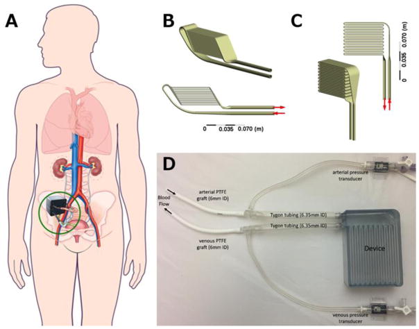
End stage kidney disease (ESKD) costs the Centers for Medicare and Medicaid Services over $30 billion annually, but the most common treatment for ESKD, dialysis, fails to fully restore health (U.S. Renal Data System, USRDS 2016 Annual Data Report: Epidemiology of Kidney Disease in the United States., 2016). Kidney transplant provides the best long-term survival, quality of life, and lowest overall costs; however, transplant is limited by scarcity of donor organs. Our team is pursuing an implantable artificial kidney (IAK; Figure 1), comprised of a hemofilter for waste product removal and a renal tubule cell-based bioreactor to mimic renal transport and metabolic functions (Kensinger et al., 2016). High-efficiency silicon nanopore membranes used in the hemofilter permit precise size-selective filtration and provide a hydraulic permeability higher than that of commercially-available hollow fiber filters used in clinical dialysis (Conlisk et al., 2009; Fissell et al., 2009; Kim et al., 2016). However, this IAK approach presents unique engineering challenges.
Figure 1.
(A) Conceptual drawing of implantable artificial kidney (IAK) in situ. (Figure modified from Kim et al., 2015 ((Kim et al., 2015), with permission from Frontiers in Bioscience.) The two candidate designs, parallel (B) and serpentine (C), are shown from two angles. Both devices have 20 channels to house nano-pore filters. The channels are arranged in parallel for the parallel device and in series for the serpentine device. (D) Photograph of experimental set up for in vivo determination of pressure boundary conditions. Arrows indicate flow direction.
An IAK must be highly biocompatible to prevent the need for repeat procedures to replace or repair failed devices. As part of this biocompatibility, thrombogenicity must be negligible as the patient is continuously exposed to the surgically implanted device. Previous in vivo experiments suggest the blood in the hemofilters experiences sub-hemolytic shear conditions (Kensinger et al., 2016) that are not expected to induce erythrocyte damage, and the design criteria for the IAK eliminates shear fields expected to produce hemolysis. However, the flow fields may induce thrombogenic changes in platelets due to relatively long exposure times to low wall shear stress (WSS) and short term exposure to high WSS(Hellums et al., 1987). This suggests stress-time exposure is a useful criterion for evaluating device thrombogenicity. Previously, a Lagrangian stress accumulation description of blood damage was shown to correlate with platelet activation (Piatti et al., 2015). This approach considers both the shear load of platelets and duration of exposure, and it has been used to analyze blood-contacting devices (Alemu et al., 2010; Morbiducci et al., 2009; Pelosi et al., 2014). We have applied this approach in a novel application: thrombogenicity assessment of IAK hemofilter designs.
The focus of this paper is the use of computational fluid dynamics (CFD) to refine and evaluate two candidate clinical-scale IAK designs based upon hemodynamics and numerically-predicted blood damage. A concern in this application is the expected residence time of platelets in these devices, particularly in slow flow regions near the wall. Long exposure to low WSS is expected to induce sustained platelet activation that may cause clotting in the device or in a distant location. Therefore, the goal is to produce flow fields that avoid WSS extremes associated with hemolysis and platelet activation. In this study, CFD was used to iteratively refine device features to minimize pathophysiologically-relevant WSS regions. In addition, a stress accumulation method was used to estimate platelet activation produced by the candidate IAK designs.
2. Methods
The IAK transports blood from the arterial circulation, across parallel plate membranes for filtration, and back to the venous system. The IAK inlet and outlet are in close proximity to facilitate anastomosis to adjacent blood vessels. Maintaining a target operating filtration rate of 30 ml/min requires significant membrane surface area (Fissell et al., 2009). Containing this surface area within a volume similar to that of a native kidney requires a flow path with either multiple branches or numerous turns. Two full-scale candidate devices that distribute pulsatile blood to parallel-plate filters were evaluated: a parallel channel device and a serial channel, or serpentine device (Figure 1). An additional requirement for the blood flow path is maintaining fluid shear stresses that are neither so low that stasis regions lead to coagulation nor so high that blood damage ensues. Both designs present challenges for minimizing the presence of low WSS regions. Therefore, geometric features were refined to reduce regions of low WSS. Finally, platelet stress accumulation (SA) was predicted for each of the devices, using a physiologic, pulsatile simulation.
2.1. Flow path design features
Within the IAK, an inlet manifold distributes flow to the rectangular channels housing silicon nanopore membranes, and an outlet manifold collects the blood flow from the filtration region and returns it to the venous circulation. The membranes are organized on two opposing sides of each channel. The dimensions of the channels were chosen such that the form factor of the IAK is similar to a human kidney. Channel heights were chosen to maintain a WSS greater than 1 Pa and to maintain a transmembrane pressure difference sufficient for filtration. The parallel path device had 20 channels 0.5 mm in height with a width of 30.5 mm and length of 67 mm. The serial, serpentine path device had 20 channels 2 mm in height with a width of 32 mm and length of 65 mm. The pressure drop along the device increases with length of the conduit. Since the serpentine design has a much longer path length than the parallel design, the channel height is larger for the serpentine device than for the parallel device. The design of the parallel device requires branching from the inlet diffuser to the channels and merging to the outlet collector, while the serpentine requires 180 degree turns between the filtration passages. The geometry of these branch points and turns is constrained by the hemodynamic need to avoid stagnation and blood damage.
2.2. Simulation details
The devices were designed in SolidWorks 2016 (Dassault Systèmes; Vélizy-Villacoublay, France). The computational grids were generated using Ansys Meshing (Ansys, Inc.; Cannonsburg, PA); simulations were conducted in Fluent v. 17.2 (Ansys, Inc.); and CFD-Post (Ansys, Inc.) was used to visualize results. Entrance and exit conduits of 80 mm, representing inlet and outlet graft lengths, were included in the simulations. The geometries were discretized using hexahedral meshes with refinement near walls for channel regions and turns and using tetrahedral meshes with prism element inflation layers near walls for manifold regions. Grid independence was determined by increasing the number of elements in each model by 50%. Between successive grid refinements, the solution was determined grid independent if the velocity error at the outlet was less than 3%. The resulting models contained 2.2 and 7.8 million elements for the serpentine and parallel devices, respectively. For all simulations, the flow was laminar and the blood was considered Newtonian with a density of 1060 kg/m3 and viscosity of 0.0035 Pa-s.
2.2.1. Steady flow CFD evaluations
Simulations were conducted on device designs to iteratively refine device features, with particular focus on turns and branches proximal of the filtration channels. These simulations were conducted under steady flow conditions at a representative renal blood flow rate of 750 ml/min. The steady state models identified regions of low WSS (< 1 Pa), and subsequently the geometries were altered to eliminate or mitigate these zones.
2.2.2. Stress accumulation simulations
When implanted, the cardiac-pressure driven IAK will operate under pulsatile flow conditions. Thus, it is critical to simulate its operation under representative physiological conditions. The relevant boundary conditions were determined by measuring pressure drop across prototype devices in vivo.
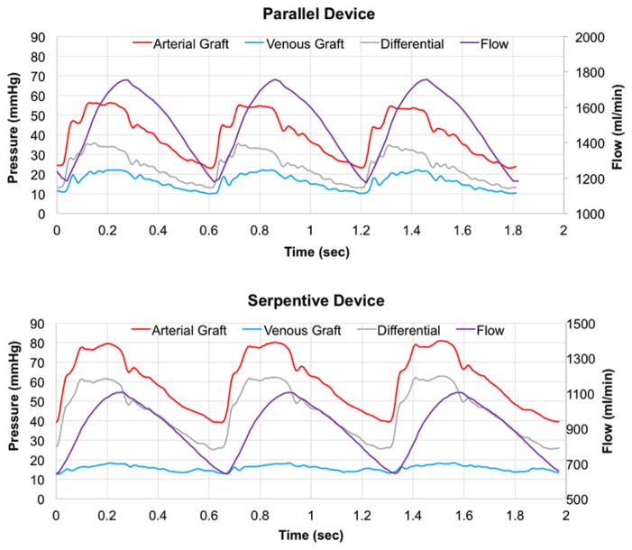
Animal experiments were reviewed and approved by PMI (San Carlos, CA) Institutional Animal Care and Use Committee. Prototypes were 3D printed using a stereolithography apparatus with Somos WaterShed XC 11122 material by Proto Labs (Maple Plain, MN). A prototype of each design was connected to the circulatory system of a 38 kg Yucatan pig. The devices were connected via 6 mm PTFE grafts to the right carotid artery and right external jugular vein. Tygon tubing was attached to the inlet and outlet of each device. Polycarbonate tee fittings, connecting the grafts to the Tygon tubing, were attached to pressure transducers to measure the pulsatile arterial and venous static pressures (Figure 1). The pulsatile pressure difference across each device was applied as the time-varying boundary condition for the simulations (Figure 2).
Figure 2.
Graphs of in vivo-measured pressures (mmHg) and numerically simulated flow (ml/min) over time for the parallel device (top panel) and serpentine device (bottom panel).
2.2.2.1. Single pass stress accumulation estimates
The design-specific platelet SA was calculated using Lagrangian particle tracking methods (Marom and Bluestein, 2016; Xenos et al., 2010) to estimate the distribution of SA values. The measured pulsatile pressure profiles were applied as boundary conditions at the entrance and exit lengths. In each device, approximately 10,000 particle tracks were seeded using a uniform, rectangular grid spacing at the entrance of the device at the local velocity. The particle count for each track was proportional to the local flow velocity and produced a total particle mass fraction of 0.5%, which is representative of normal platelet mass fraction. The fully-coupled, discrete phase model was used to track neutrally buoyant particles 3 μm in diameter, representing platelets. The total simulation time was sufficient to allow 10 volume changes based on the peak flow rate. Time steps were 0.02 s and 0.01 s for the parallel and serpentine models, respectively. The time steps were selected to produce a Courant number < 4. The maximum/minimum Reynolds numbers were 29/20 for the parallel device channels and 370/220 for the serpentine channels. As the particles traversed the device, the local shear stress levels on the particles were integrated along each particle track to calculate SA for each particle using an User Defined Function within Fluent. We used linear and power law models of platelet stress accumulation. These models are of the form previously proposed for blood damage (Blackshear et al., 1965).
The linear model, as shown in equation (1), was used to compare stress accumulation [Pa-s] for a single pass through the IAK designs, as used in previous applications (Alemu et al., 2010; Alemu and Bluestein, 2007; Girdhar et al., 2012; Pelosi et al., 2014; Sheriff et al., 2010; Xenos et al., 2010).
| (1) |
where i is the index of a particle tracking time step, k is the number of time steps for a particle track, τi is the shear stress (Pa) on the particle during the time step, and Δti is the time step size (s).
A normalized power-law model for platelet SA was fit to the platelet activation limit summarized by Hellums et al. (Hellums et al., 1987) for steady state, constant shear conditions, producing
| (2) |
Using this convention, stress-time combinations on the line of activation reported by Hellums et al. (Hellums et al., 1987) have values of 1. Values greater than 1 are expected to cause platelet activation. To implement this approach under dynamic flow conditions, the relationship was taken to apply incrementally, and stresses were summed over the flight of the particle,
| (3) |
As the particles exited the device, the SA for each particle track was recorded. A probability density function (PDF) of SA was generated for each device from these sample particle tracks. This PDF statistically represents the predicted distribution of SA values experienced by platelets as they traverse the device, providing a “thrombogenic footprint” (Alemu and Bluestein, 2007). Subsequently, PDFs for different designs can be compared to assess the relative differences in the footprint. Entrance and exit lengths were not included in the SA calculations.
2.2.2.2. Repeated pass stress accumulation estimates
During its lifetime, an individual platelet will flow through the artificial kidney many times and accumulate stress with each pass. We have estimated platelet lifetime SA from the single pass results using a post-processing repeated passage approach (Marom and Bluestein, 2016; Slepian et al., 2013). Considering a platelet lifetime of approximately 7 days and a 10% blood flow to the native kidney, a platelet will pass through the artificial kidney approximately 1,000 times during its lifetime. To estimate the lifetime SA, each of the 1,000 passes of the “platelet” through the device was randomly selected from the initial 10,000 single pass particle tracks. The stresses were summed over the 1,000 passes of the “platelet” through the device to estimate the lifetime SA for that “platelet”. To create a statistical distribution of the likelihood of the damage, this process was repeated for 100,000 “platelets” to produce a lifetime stress accumulation PDF. These distributions provide an estimate of the likelihood for each device to cause platelet activation.
3. Results
3.1. Steady flow CFD evaluations
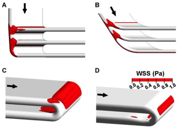
Original and refined geometries are shown for the branch points of the parallel device (Figure 3). Even though the channel entries of the initial parallel design were fully radiused, a band of low WSS was present on the inner wall of the branching regions proximal of the filtration channels. Angling the manifold, staggering the filters to reduce the turning angle and contouring the flow dividers eliminated the band of low WSS across the inner wall of the branches. Subsequent revisions decreased the magnitude of the remaining low WSS regions on the side walls of the branch regions.
Figure 3.
Low wall shear stress (WSS< 1 Pa) regions and design feature improvements at steady flow. Top row demonstrates (A) initial and (B) revised parallel plate manifold features. Bottom row demonstrates (C) initial and (D) revised serpentine turn features. The span of low WSS regions was reduced using CFD to guide design iterations.
Initial designs for the serpentine flow path used constant-radius turns to connect one blood channel to the next (Figure 3). Simulations demonstrated regions of low WSS on the inner wall of 180° turns proximal of filtration channels. Although these are not circular conduits, this phenomena is expected as a feature of Dean-type flow (Dean, 1927). We modified the turns by narrowing the conduit cross-section at areas of low wall shear stress, improving subsequent designs. The low WSS regions present on both outer and inner walls of the 180° turns were reduced in size and severity with CFD-directed geometry refinement.
3.2. Stress accumulation simulations
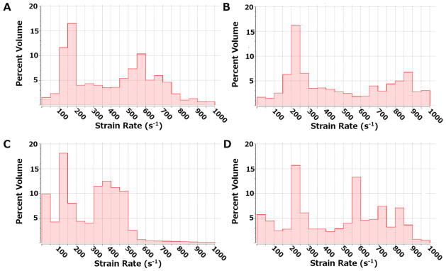
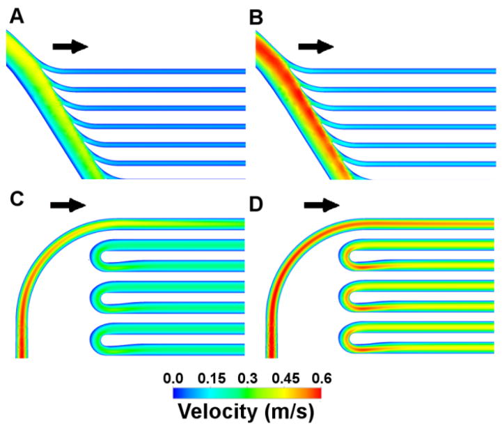
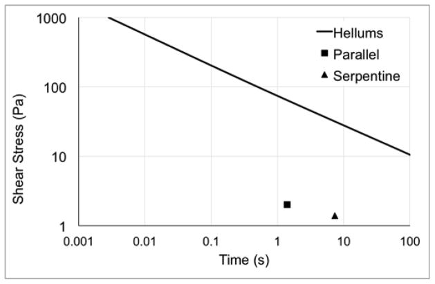
Previous studies indicate that the Newtonian assumption is sufficient for flow fields with shear rates of at least 100 s−1 (Pedley, 1980). Histograms illustrate the shear rate distributions throughout the model volume at both maximum and minimum flow rates (Figure 4). The parallel model has less than 5% of the volume that experiences shear rates <100 s−1, while the serpentine model has less than 11–15% of the volume exposed to shear rates <100 s−1. The velocity distributions at maximum flow rates, 1750 ml/min and 1100 ml/min for the parallel and serpentine devices, respectively, are included in Figure 5. Both devices operate under mean shear stress conditions and residence times below the platelet activation limit summarized by Hellums et al. (Hellums et al., 1987) (Figure 6).
Figure 4.
Histograms illustrating the distribution of strain rates for the parallel design at minimum (A) and maximum (B) flow rates and for the serpentine design at minimum (C) and maximum (D) flow rates.
Figure 5.
Velocity distributions are shown for the parallel device at maximum (1750 ml/min; A) and minimum (1170 ml/min; B) flow rates and for the serpentine device at maximum (1100 ml/min; C) and minimum (640 ml/min; D) flow rates.
Figure 6.
Platelet activation limit summarized by Hellums et al. (Hellums et al., 1987) and values of average shear stress and residence times for the parallel (square) and serpentine (triangle) devices.
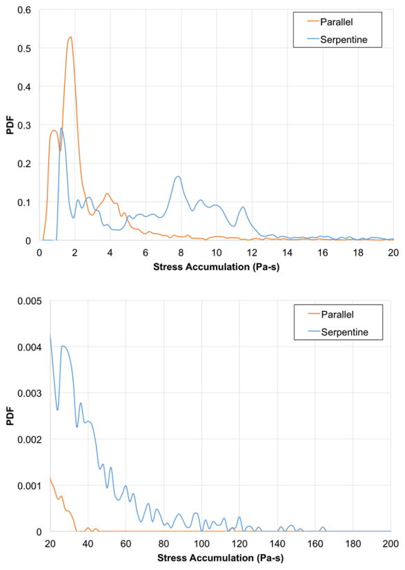
Using the linear stress accumulation model, the parallel plate and serpentine geometries generated mean single-pass SA of 2.8 and 10.4 Pa-s, respectively (Figure 7). These PDFs demonstrate different patterns for the two devices. The PDF for the parallel device demonstrates increased likelihood of platelets experiencing lower stress-time product conditions. While, the serpentine device PDF predicts a sustained likelihood of a stress-time product of 10 Pa-s, reflecting its increased flow path length and exposure time.
Figure 7.
Top panel shows the linear, single-pass probability density functions (PDFs) of stress accumulation (Pa-s) for the parallel device (orange line) and serpentine device (blue line). Bottom panel shows details on the “tails” at the higher range (20–200 Pa-s) of stress accumulation.
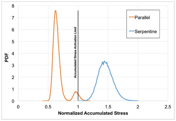
The power law model predictions of lifetime normalized SA were generated for both devices (Figure 8). The lifetime normalized SA PDF demonstrates that the parallel design exposes platelets to hemodynamic conditions below a value of 1, which coincides with the activation limit shown in Hellums et al. (Hellums et al., 1987). An overall broader distribution, the serpentine device PDF exceeded the Hellums activation limit.
Figure 8.
The power law probability density functions (PDFs) for normalized lifetime stress accumulation using a power law model for the parallel (orange line) and serpentine (blue line) devices. The vertical line at a normalized stress accumulation of 1 indicates the activation limit described in Hellums, et al. (Hellums et al., 1987).
4. Discussion
Hemodynamics influence device thrombogenicity, and evaluation of flow fields is a critical step in device design (Chiu et al., 2014; Duraiswamy et al., 2008; Ge et al., 2005; Hochareon et al., 2004; Lee et al., 2012; Li and Kleinstreuer, 2006; Loth et al., 1997; Moake et al., 1986; Morbiducci et al., 2009; Pelosi et al., 2014; Rambod et al., 2010; Song et al., 2013; Topper et al., 2014; Yin et al., 2004). In this study, we assessed the hemodynamics-related thrombogenicity of two candidate flow paths for hemofilters using CFD. We iteratively assessed and revised geometric features to reduce the size and severity of low WSS areas. Further, we demonstrated that the parallel device results in lower platelet SA than the serpentine device.
Previous investigations employed Eulerian (Hansen et al., 2015), platelet residence time (Esmaily-Moghadam et al., 2013), and combination transport and hemodynamics stress (Shadden and Hendabadi, 2013) approaches to model blood damage. In this study, we applied a Lagrangian-based computational approach previously correlated with in vitro measures of platelet activation (Piatti et al., 2015). This method provides a distribution (or “footprint”) of stress exposure imparted on the platelets by the flow field of each device. While this approach has been applied extensively in assessment of blood contacting devices (Alemu et al., 2010; Alemu and Bluestein, 2007; Girdhar et al., 2012; Morbiducci et al., 2009; Pelosi et al., 2014; Sheriff et al., 2010; Xenos et al., 2010), this is the first implementation in an artificial kidney application. Under the designed sub-hemolytic operating conditions, the IAK will not experience as high shear fields as would be anticipated for cardiac-related applications. In addition, unlike previously investigated extracorporeal devices, the IAK is cardiac-pressure driven.
Using a linear SA model, the parallel plate and serpentine geometries generated mean, single-pass SA of 2.8 and 10.4 Pa-s, respectively. The extended tails demonstrated in both PDFs arise from platelets that follow trajectories near the walls of the device. These near-wall platelets experience higher levels of stress because the velocity gradients are higher near the walls. This phenomenon is compounded by longer residence times for these trajectories as the velocity near the walls is lower. In addition, for the serpentine design, the flow moving close to the walls remains along the walls for the full length of the channel sections. There is limited mixing around the turns for the stable, laminar flow patterns within the channels of the serpentine design. Previous studies of heart valve stress accumulations report mean values in the 1–2 Pa-s range (Alemu et al., 2010; Alemu and Bluestein, 2007; Bluestein et al., 1997; Dumont et al., 2007; Morbiducci et al., 2009; Xenos et al., 2010), and those of oxygenators are approximately 20 Pa-s when the porous region of the oxygenator is included (Pelosi et al., 2014). These indicate mean single-pass SA values for the IAK are between those of the heart valves and oxygenator. While instantaneous shear conditions within these kidney blood flow paths are not as elevated as those in some foci of heart valves, the mean, single-pass residence times experienced by platelets in the kidney devices are relatively long at 1.4 and 7.3 s for the parallel and serpentine devices, respectively. The particularly long residence times in the serpentine device likely contribute to the broader PDF for the single-pass estimates. However, it should be noted that both devices exhibit mean shear stress and single-pass residence time values (Figure 6) well below the activation limit determined by Hellums et al. (Hellums et al., 1987).
Studies have demonstrated that stress-activated platelets remain prothrombotic in subsequent low shear stress flow fields (Sheriff et al., 2010). Thus, consideration of the SA over the life of the platelet – in part influenced by the number of times a platelet passes through potentially thrombogenic regions of devices – is vital for developing guidelines for design. The lifetime normalized SA PDFs indicate that the parallel plate design has less thrombogenic potential than the serpentine form. Further distinguishing the flow paths, the parallel design demonstrated normalized platelet lifetime SA values less than that of the activation limit indicated in Hellums et al. (Hellums et al., 1987), while the serpentine exceeded it. This demonstrates the necessity of applying a multiple-pass approach for differentiating designs that produce single-pass activation values below the limit indicated by Hellums et al.
A Newtonian model for viscosity was used in this study. Previously, this model was shown to be sufficient in flow fields with shear >100 s−1 (Pedley, 1980), and the majority of both flow fields exceeded this threshold. Work by Aycock et al. (Aycock et al., 2016) emphasized the value of employing a non-Newtonian model of viscosity when estimating WSS; however, Ballyk et al. (Ballyk et al., 1994) reported that the Newtonian assumption impacted WSS calculations less for pulsatile flow than for steady flow conditions. Given the pulsatile flow conditions implemented in this study and that the vast majority of both flow fields exceeded the 100 s−1 threshold, the outcome of the current study remains unchanged: the parallel design is a better choice than the serpentine. Future studies, however, may focus on using a non-Newtonian viscosity, given the impact and feasibility demonstrated in Aycock et al. (Aycock et al., 2016).
Additional approximations include the simulation of the blood flow path only. With implementation of the nanopore membranes, the channel walls will form porous boundaries resulting in filtrate flow from the blood path, consequently producing smaller velocity gradients along the wall. Subsequent effects of filtrate flow on SA are complex due to the balance between the resultant decreasing shear stress and increasing platelet residence time. Further, although SA has been correlated with in vitro platelet activation (Piatti et al., 2015), this approach does not directly predict platelet adhesion as was demonstrated previously (Taylor et al., 2017). While these considerations will be valuable in future models, this initial study is intended to establish a baseline SA performance for each device. Finally, using the pulsatile pressure boundary conditions, the CFD-calculated mean flow rates were 1500 ml/min and 900 ml/min for the parallel and serpentine designs, respectively. As expected, given the decreased resistance of the IAK hemofilter relative to the native kidney, these values are considerably higher than renal flow to native kidneys. Future studies will explore methods to reduce the flow rates to more physiological levels and the resulting impact on the platelet SA PDFs.
Minimizing platelet stress accumulation is a necessary but not sufficient condition for determining suitability of a blood-contacting device. Further, these simulations do not capture phenomena such as platelet margination or biochemical activation. Ultimately, additional in vivo or in vitro experiments are critical to determine biocompatibility of any implantable device. However, in this application, we suggest platelet stress analysis provides an efficient and effective basis for winnowing a battery of candidate designs, thus minimizing the number of subsequent experiments.
Conclusions
Minimizing the thrombogenicity of an IAK flow path is vital for long-term operation under minimal anti-coagulation therapy. Hemodynamic simulations and numerical estimations of blood damage were used to improve and characterize predicted thrombogenicity of two potential IAK designs. Consideration of low wall shear stress was integrated into the design cycle for minimizing areas of slow-flowing blood. Further, a Lagrangian-based method of estimating platelet SA in the device was implemented using both linear and power law models. The single-pass SA distributions indicated a decreased likelihood of thrombogenic potential for the parallel design than for the serpentine. Numerical estimations of platelet lifetime SA differentiated between device designs, predicting the parallel device had lower thrombogenic potential than the serpentine device. Further, when compared to known platelet activation limits, the parallel design has reduced thrombogenic potential, and thus is more favorable for application as an IAK.
Acknowledgments
This study was supported by National Institutes of Health (1R01EB014315 and 1U01EB021214) and a generous gift from the Wildwood Foundation. The authors appreciate the contributions of Charles Blaha and Susan Kram to the study.
Footnotes
Conflict of Interest Statement: Drs. Fissell and Roy have ownership in Silicon Kidney. Co-authors Buck, Goebel, Goodin, Wright, Groszek, Fissell and Roy have patent applications on this work pending.
Publisher's Disclaimer: This is a PDF file of an unedited manuscript that has been accepted for publication. As a service to our customers we are providing this early version of the manuscript. The manuscript will undergo copyediting, typesetting, and review of the resulting proof before it is published in its final citable form. Please note that during the production process errors may be discovered which could affect the content, and all legal disclaimers that apply to the journal pertain.
References
- Alemu Y, Bluestein D. Flow-induced platelet activation and damage accumulation in a mechanical heart valve: numerical studies. Artif Organs. 2007;31:677–688. doi: 10.1111/j.1525-1594.2007.00446.x. [DOI] [PubMed] [Google Scholar]
- Alemu Y, Girdhar G, Xenos M, Sheriff J, Jesty J, Einav S, Bluestein D. Design optimization of a mechanical heart vavle for reducing valve thrombogenicity - A case study with ATS vavle. ASAIO J. 2010;56:389–396. doi: 10.1097/MAT.0b013e3181e65bf9. [DOI] [PubMed] [Google Scholar]
- Aycock KI, Campbell RL, Lynch FC, Manning KB, Craven BA. The Importance of Hemorheology and Patient Anatomy on the Hemodynamics in the Inferior Vena Cava. Ann Biomed Eng. 2016;44:3568–3582. doi: 10.1007/s10439-016-1663-x. [DOI] [PubMed] [Google Scholar]
- Ballyk PD, Steinman DA, Ethier CR. Simulation of non-Newtonian blood flow in an end-to-side anastomosis. Biorheology. 1994;31:565–86. doi: 10.3233/bir-1994-31505. [DOI] [PubMed] [Google Scholar]
- Blackshear PL, Dorman FD, Steinbach JH. Some mechanical effects that influence hemolysis. Trans Am Soc Artif Intern Organs. 1965;11:112–7. doi: 10.1097/00002480-196504000-00022. [DOI] [PubMed] [Google Scholar]
- Bluestein D, Niu L, Schoephoerster RT, Dewanjee MK. Fluid mechanics of arterial stenosis: Relationship to the development of mural thrombus. Ann Biomed Eng. 1997;25:344–356. doi: 10.1007/BF02648048. [DOI] [PubMed] [Google Scholar]
- Chiu WC, Slepian MJ, Bluestein D. Thrombus Formation Patterns in the HeartMate II Ventricular Assist Device. ASAIO J. 2014;60:237–240. doi: 10.1097/MAT.0000000000000034. [DOI] [PMC free article] [PubMed] [Google Scholar]
- Conlisk AT, Datta S, Fissell WH, Roy S. Biomolecular transport through hemofiltration membranes. Ann Biomed Eng. 2009;37:722–36. doi: 10.1007/s10439-009-9642-0. [DOI] [PMC free article] [PubMed] [Google Scholar]
- Dean WR. Note on the motion of fluid in a curved pipe London, Edinburgh, Dublin. Philos Mag J Sci. 1927;4:208–223. doi: 10.1080/14786440708564324. [DOI] [Google Scholar]
- Dumont K, Vierendeels J, Vierendeels J, Kaminsky R, van Nooten G, Verdonck P, Bluestein D. Comparison of the Hemodynamic and Thrombogenic Performance of Two Bileaflet Mechanical Heart Valves Using a CFD/FSI Model. J Biomech Eng. 2007;129:558. doi: 10.1115/1.2746378. [DOI] [PubMed] [Google Scholar]
- Duraiswamy N, Cesar JM, Schoephoerster RT, Moore JE. Effects of stent geometry on local flow dynamics and resulting platelet deposition in an in vitro model. Biorheology. 2008;45:547–61. [PubMed] [Google Scholar]
- Esmaily-Moghadam M, Hsia TY, Marsden AL. A non-discrete method for computation of residence time in fluid mechanics simulations. Phys Fluids. 2013;25:110802. doi: 10.1063/1.4819142. [DOI] [PMC free article] [PubMed] [Google Scholar]
- Fissell WH, Dubnisheva A, Eldridge AN, Fleischman AJ, Zydney AL, Roy S. High-Performance Silicon Nanopore Hemofiltration Membranes. J Memb Sci. 2009;326:58–63. doi: 10.1016/j.memsci.2008.09.039. [DOI] [PMC free article] [PubMed] [Google Scholar]
- Ge L, Leo HL, Sotiropoulos F, Yoganathan AP. Flow in a mechanical bileaflet heart valve at laminar and near-peak systole flow rates: CFD simulations and experiments. J Biomech Eng. 2005;127:782–97. doi: 10.1115/1.1993665. [DOI] [PubMed] [Google Scholar]
- Girdhar G, Xenos M, Alemu Y, Chiu WC, Lynch BE, Jesty J, Einav S, Slepian MJ, Bluestein D. Device Thrombogenicity Emulation: A Novel Method for Optimizing Mechanical Circulatory Support Device Thromboresistance. PLoS One. 2012;7:e32463. doi: 10.1371/journal.pone.0032463. [DOI] [PMC free article] [PubMed] [Google Scholar]
- Hansen KB, Arzani A, Shadden SC. Mechanical Platelet Activation Potential in Abdominal Aortic Aneurysms. J Biomech Eng. 2015;137:41005. doi: 10.1115/1.4029580. [DOI] [PMC free article] [PubMed] [Google Scholar]
- Hellums JD, Peterson DM, Stathopoulos NA, Moake JL, Giorgio TD. Studies on the Mechanisms of Shear-Induced Platelet Activation. In: Hartmann A, Kuschinsky W, editors. Cerebral Ischemia and Hemorheology. Springer Berlin Heidelberg; Berlin, Heidelberg: 1987. pp. 80–89. [DOI] [Google Scholar]
- Hochareon P, Manning KB, Fontaine AA, Tarbell JM, Deutsch S. Correlation of in vivo clot deposition with the flow characteristics in the 50 cc penn state artificial heart: a preliminary study. ASAIO J. 2004;50:537–42. doi: 10.1097/01.mat.0000145694.40637.a0. [DOI] [PubMed] [Google Scholar]
- Kensinger C, Karp S, Kant R, Chui BW, Goldman K, Yeager T, Gould ER, Buck A, Laneve DC, Groszek JJ, Roy S, Fissell WH. First Implantation of Silicon Nanopore Membrane Hemofilters. ASAIO J. 2016;62:491–495. doi: 10.1097/MAT.0000000000000367. [DOI] [PMC free article] [PubMed] [Google Scholar]
- Kim S, Feinberg B, Kant R, Chui B, Goldman K, Park J, Moses W, Blaha C, Iqbal Z, Chow C, Wright N, Fissell WH, Zydney A, Roy S. Diffusive Silicon Nanopore Membranes for Hemodialysis Applications. PLoS One. 2016;11:e0159526. doi: 10.1371/journal.pone.0159526. [DOI] [PMC free article] [PubMed] [Google Scholar]
- Kim S, Fissell WH, Humes DH, Roy S. Current strategies and challenges in engineering a bioartificial kidney. Front Biosci (Elite Ed) 2015;7:215–28. doi: 10.2741/e729. [DOI] [PMC free article] [PubMed] [Google Scholar]
- Lee JC, Lee K, Kim HC. Mathematical analysis for internal filtration of convection-enhanced high-flux hemodialyzer. Comput Methods Programs Biomed. 2012;108:68–79. doi: 10.1016/j.cmpb.2012.01.001. [DOI] [PubMed] [Google Scholar]
- Li Z, Kleinstreuer C. Analysis of biomechanical factors affecting stent-graft migration in an abdominal aortic aneurysm model. J Biomech. 2006;39:2264–2273. doi: 10.1016/j.jbiomech.2005.07.010. [DOI] [PubMed] [Google Scholar]
- Loth F, Jones SA, Giddens DP, Bassiouny HS, Glagov S, Zarins CK. Measurements of velocity and wall shear stress inside a PTFE vascular graft model under steady flow conditions. J Biomech Eng. 1997;119:187–94. doi: 10.1115/1.2796079. [DOI] [PubMed] [Google Scholar]
- Marom G, Bluestein D. Lagrangian methods for blood damage estimation in cardiovascular devices - How numerical implementation affects the results. Expert Rev Med Devices. 2016;13:113–122. doi: 10.1586/17434440.2016.1133283. [DOI] [PMC free article] [PubMed] [Google Scholar]
- Moake JL, Rudy CK, Troll JH, Weinstein MJ, Colannino NM, Hong SL, Koutcher JA, Melaragno AJ, Manner CE. von Willebrand factor abnormalities and endothelial cell perturbation in a patient with acute thrombotic thrombocytopenic purpura. Am J Med Sci. 1986;291:47–50. doi: 10.1097/00000441-198601000-00009. [DOI] [PubMed] [Google Scholar]
- Morbiducci U, Ponzini R, Nobili M, Massai D, Montevecchi FM, Bluestein D, Redaelli A. Blood damage safety of prosthetic heart valves. Shear-induced platelet activation and local flow dynamics: A fluid–structure interaction approach. J Biomech. 2009;42:1952–1960. doi: 10.1016/j.jbiomech.2009.05.014. [DOI] [PubMed] [Google Scholar]
- Pedley T. The Fluid Mechanics of Large Blood Vessels. Cambridge University Press; 1980. [Google Scholar]
- Pelosi A, Sheriff J, Stevanella M, Fiore GB, Bluestein D, Redaelli A. Computational evaluation of the thrombogenic potential of a hollow-fiber oxygenator with integrated heat exchanger during extracorporeal circulation. Biomech Model Mechanobiol. 2014;13:349–361. doi: 10.1007/s10237-012-0445-0. [DOI] [PMC free article] [PubMed] [Google Scholar]
- Piatti F, Sturla F, Marom G, Sheriff J, Claiborne TE, Slepian MJ, Redaelli A, Bluestein D. Hemodynamic and thrombogenic analysis of a trileaflet polymeric valve using a fluid–structure interaction approach. J Biomech. 2015;48:3641–3649. doi: 10.1016/j.jbiomech.2015.08.009. [DOI] [PMC free article] [PubMed] [Google Scholar]
- Rambod E, Beizai M, Rosenfeld M. An experimental and numerical study of the flow and mass transfer in a model of the wearable artificial kidney dialyzer. Biomed Eng Online. 2010;9:21. doi: 10.1186/1475-925X-9-21. [DOI] [PMC free article] [PubMed] [Google Scholar]
- Shadden SC, Hendabadi S. Potential fluid mechanic pathways of platelet activation. Biomech Model Mechanobiol. 2013;12:467–474. doi: 10.1007/s10237-012-0417-4. [DOI] [PMC free article] [PubMed] [Google Scholar]
- Sheriff J, Bluestein D, Girdhar G, Jesty J. High-Shear Stress Sensitizes Platelets to Subsequent Low-Shear Conditions. Ann Biomed Eng. 2010;38:1442–1450. doi: 10.1007/s10439-010-9936-2. [DOI] [PMC free article] [PubMed] [Google Scholar]
- Slepian MJ, Alemu Y, Soares JS, Smith GR, Einav S, Bluestein D, Bluestein D. The Syncardia™ total artificial heart: in vivo, in vitro, and computational modeling studies. J Biomech. 2013;46:266–275. doi: 10.1016/j.jbiomech.2012.11.032. [DOI] [PMC free article] [PubMed] [Google Scholar]
- Song JJ, Guyette JP, Gilpin SE, Gonzalez G, Vacanti JP, Ott HC. Regeneration and experimental orthotopic transplantation of a bioengineered kidney. Nat Med. 2013;19:646–51. doi: 10.1038/nm.3154. [DOI] [PMC free article] [PubMed] [Google Scholar]
- Taylor JO, Yang L, Deutsch S, Manning KB. Development of a platelet adhesion transport equation for a computational thrombosis model. J Biomech. 2017;50:114–120. doi: 10.1016/j.jbiomech.2016.11.012. [DOI] [PubMed] [Google Scholar]
- Topper SR, Navitsky MA, Medvitz RB, Paterson EG, Siedlecki CA, Slattery MJ, Deutsch S, Rosenberg G, Manning KB. The Use of Fluid Mechanics to Predict Regions of Microscopic Thrombus Formation in Pulsatile VADs. Cardiovasc Eng Technol. 2014;5:54–69. doi: 10.1007/s13239-014-0174-x. [DOI] [PMC free article] [PubMed] [Google Scholar]
- U.S. Renal Data System. USRDS 2016 Annual Data Report: Epidemiology of Kidney Disease in the United States. Bethesda, MD: 2016. [Google Scholar]
- Xenos M, Girdhar G, Alemu Y, Jesty J, Slepian M, Einav S, Bluestein D. Device Thrombogenicity Emulator (DTE) - Design optimization methodology for cardiovascular devices: A study in two bileaflet MHV designs. J Biomech. 2010;43:2400–2409. doi: 10.1016/j.jbiomech.2010.04.020. [DOI] [PMC free article] [PubMed] [Google Scholar]
- Yin W, Alemu Y, Affeld K, Jesty J, Bluestein D. Flow-induced platelet activation in bileaflet and monoleaflet mechanical heart valves. Ann Biomed Eng. 2004;32:1058–66. doi: 10.1114/b:abme.0000036642.21895.3f. [DOI] [PubMed] [Google Scholar]


