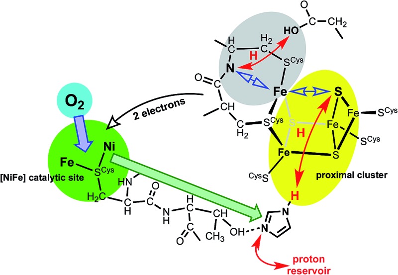
 A new mechanistic model is developed for the sequence of events by which oxygen-tolerant [NiFe] hydrogenase enzymes respond to O2.
Abstract
The [NiFe] hydrogenases use an electron transfer relay of three FeS clusters – proximal, medial and distal – to release the electrons from the principal reaction, H2 → 2H+ + 2e–, that occurs at the Ni–Fe catalytic site. This site is normally inactivated by O2, but the subclass of O2-tolerant [NiFe] hydrogenases are able to counter this inactivation through the agency of an unusual and unprecedented proximal cluster, with composition [Fe4S3(Scys)6], that is able to transfer two electrons back to the Ni–Fe site and effect crucial reduction of O2-derived species and thereby reactivate the Ni–Fe site. This proximal cluster gates both the direction and the number of electrons flowing through it, and can reverse the normal flow during O2 attack. The unusual structures and redox potentials of the proximal cluster are known: a structural change in the proximal cluster causes changes in its electron-transfer potentials. Using protein structure analysis and density functional simulations, this paper identifies a closed protonic system comprising the proximal cluster, some contiguous residues, and a proton reservoir, and proposes that it is activated by O2-induced conformational change at the Ni–Fe site. This change is linked to a key histidine residue which then causes protonation of the proximal cluster, and migration of this proton to a key μ3-S atom. The resulting SH group causes the required structural change at the proximal cluster, modifying its redox potentials, and leads to the reversed electron flow back to the Ni–Fe site. This cycle is reversible, and the protons involved are independent of those used or produced in reactions at the active site. Existing experimental support for this model is cited, and new testing experiments are suggested.
Introduction
The hydrogenase enzymes catalyse the reactions H2 ↔ 2H+ + 2e–, and occur in two main groups, those with an [FeFe] active site and those with an [NiFe] active site.1–4 The [FeFe] enzymes mainly reduce protons, while the [NiFe] enzymes mainly oxidise H2. These hydrogenases are generally very sensitive to O2, but there is a group of [NiFe] hydrogenases found in aerobic bacteria that are able to oxidise H2 in the presence of O2.5–10 The ability of these O2-tolerant hydrogenases to concurrently oxidise H2 and reduce O2 is of obvious chemical and technological interest.7,9,11–16
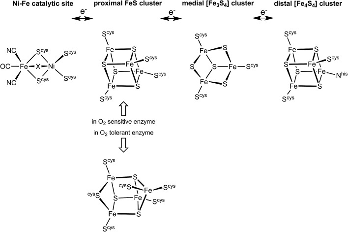
There is substantial knowledge of the protein structures and of the intermediates and mechanism for normal reactivity at the (cysS)2Ni(μ-Scys)2Fe(CN)2(CO) catalytic site (Scheme 1).2,3,9,17–23 The inactivation caused by O2 introduces OH or O2H species at the bridging X site, forming inactive species that are ‘ready’ (Ni-B) or ‘unready’ (Ni-A) for reactivation.1,8,19,24–26 A key attribute of the O2-tolerant enzymes is modification of the redox potentials in the chain of three FeS clusters (Scheme 1) that transfer electrons to and from the catalytic site.5,7,8 In recent years the crystal structures of these O2-tolerant enzymes from species Hydrogenovibrio marinus (Hm), Ralstonia eutropha (Re), Escherichia coli Hyd-1 (EcHyd-1) and Salmonella enterica Hyd-5 (SeHyd-5) have revealed their distinctive structural property, which is the presence of an unusual and unprecedented Fe4S3(Scys)6 cluster27–31 in place of the standard Fe4S4(Scys)4 cluster at the proximal location, adjacent to the [Ni–Fe] active site, in the electron transfer chain.
Scheme 1. The electron transfer relay of metal clusters in [NiFe] hydrogenases, with the different proximal clusters related to O2 sensitivity. At the Ni–Fe catalytic site X is normally H or absent, but is OH or O2H in inactive states.
This proximal cluster occurs in three oxidation states, described in terms of the core charges as [Fe4S3]3+ reduced (RED), [Fe4S3]4+ oxidised (OX), and [Fe4S3]5+ super-oxidised (SOX). The reduction potentials for the one-electron steps between these states are anomalously close, namely +232 mV (SOX/OX) and +87 mV (OX/RED) in Aquifex aeolicus,32 (and ca. +160 mV, –60 mV in Alcaligenes eutrophus 6,33). In Hm the two successive potentials are +230 and +30 mV, and in a slightly modified form of Hm are +175 and +90 mV.34 This close separation of ca. 150–200 mV between the [Fe4S3]5+/4+ and [Fe4S3]4+/3+ potentials contrasts the normal separations between successive one-electron transfer potentials for [Fe4S4] clusters of 600 to 1000 mV,35–37 and suggests that a structural change occurs in the sequence RED–OX–SOX.
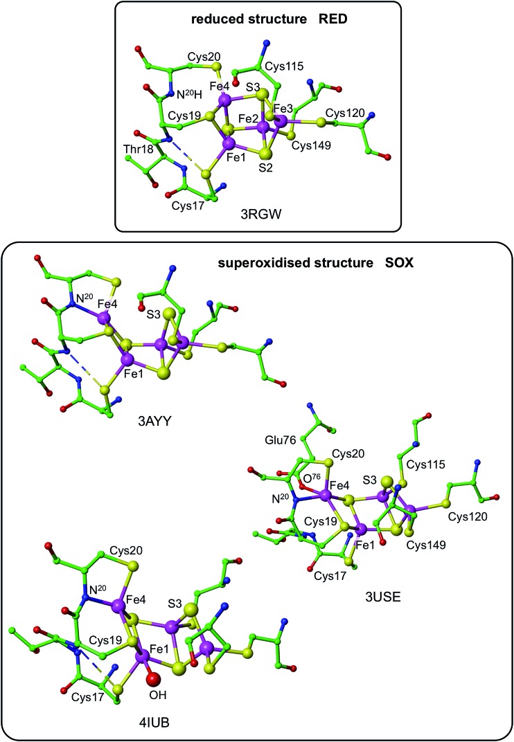
Three crystallographic investigations27–29 have revealed that the structure of the RED form of the proximal cluster in three different species is that shown in the upper panel of Fig. 1. The RED cluster is derived from standard cubanoid Fe4S4(SR)4 by the opening of one Fe–(μ3-S) bond, replacement of μ3-S with doubly-bridging Cys19 thiolate, and adding another cysteine to the released Fe3 atom (the atom numbering used here is that of Re 28 and EcHyd-129), resulting in the composition Fe4(μ3-S)3(μ-SR)(SR)5. The super-oxidised SOX structure of the proximal cluster is distinctly different (Fig. 1, lower panel): the Fe4–S3 bond no longer exists, and the main chain amide of Cys20 is deprotonated and rotated so as form a bond to Fe4, maintaining the four-coordination of Fe4. This core structure is even more open than that of RED. Variations in the structure of the SOX form have been reported in the diffraction analyses of crystals prepared in different ways, and from different organisms. Crystals from EcHyd-1 showed evidence of variable conformations of the Glu76 side-chain, and of its coordination to Fe4 (Fig. 1, ; 3USE).29 A recent crystallographic analysis of the SOX form of Re (PDB ; 4IUB, Fig. 1)30 revealed an additional OH ligand at Fe1. Further evidence for the OH ligand on Fe1 in the Re crystals has been provided, together with possible reasons for non-detection of this OH in the Hm and EcHyd-1 crystals.30 On the basis of the controlled redox state of their crystals, Frielingsdorf et al. 30 concluded that the structure of the proximal cluster at the intermediate OX level is very similar to that of RED. The structures of the proximal cluster in the RED and SOX states are unprecedented.
Fig. 1. Structures of the reduced (RED, upper panel) and superoxidised (SOX, lower panel) states of the proximal cluster. PDB codes are marked [3RGWRalstonia eutropha (Re),28; 3AYYHydrogenovibrio marinus,27; 3USEEscherichia coli Hyd-1 (EcHyd-1),29; 4IUBRalstonia eutropha,30] and atom/residue numbering is that of the Re and EcHyd-1 structures. In the reduced cluster ; 3RGW the Fe4–S3 and Fe4–N20 distances are bonding (2.31 Å) and non-bonding (3.29 Å), while in the superoxidised form these interactions are reversed, Fe4–S3 4.01, 3.90 Å, Fe4–N20 2.09, 2.11 Å. The SOX form has been observed with an OH ligand on Fe1 (; 4IUB), and a bonding interaction between the side-chain of Glu76 and Fe4 was detected for EcHyd-1 (; 3USE). The broken line is a hydrogen bond from N18–H to S17.
The structures of the three redox states of the proximal cluster reveal the reason for their unusual reduction potentials. In the SOX form the replacement of a μ3-S ligand on Fe4 by deprotonated amide stabilises oxidised Fe38 and markedly lowers its reduction potential to a value in the physiological potential range and only ca. 150 mV more positive than the OX reduction potential.7,8,28,29,32,34,37 Additional coordination of OH– on Fe1 would also stabilise the oxidised cluster.30
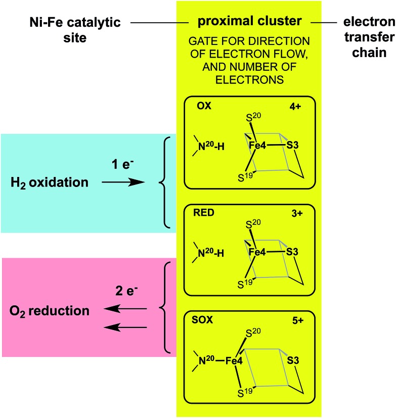
The redox potentials of the proximal cluster allow it to collect one electron (OX → RED) from the Ni–Fe site as part of the H2 oxidation cycle, and to discharge two electrons (RED → SOX) to the Ni–Fe site when it is necessary to enable four-electron reduction of O2 (the other two electrons are believed to come from the medial cluster and the Ni–Fe site) and avoid inactivation of the Ni–Fe site.6,8,10,24–26,30,34 The proximal cluster has a key function in gating either one electron from or two electrons to the catalytic site (Fig. 2).
Fig. 2. The gating function of the proximal cluster, accepting one electron during oxidation of H2, or providing two electrons towards reduction of O2.
Questions: what is the trigger mechanism?
These data and model just outlined provide a plausible account of the unusual ability of the electron transport chain to move electrons in two opposing directions depending on the substrate, H2 or O2, that presents at the Ni–Fe catalytic site. In the presence of O2 the proximal cluster adopts the SOX structure when it releases two ‘rescue’ electrons.34 How can the catalytic site, when challenged by O2, signal to the proximal site the need for two electrons, and cause their delivery? The key must be the geometrical change that occurs at the proximal cluster and changes its OX/SOX potential from an otherwise inaccessible value (at least 500 mV too positive) to a value close to the RED/OX potential. What chemical event at the proximal cluster causes the necessary geometrical changes, the severing of the Fe4–S3 bond, the deprotonation of N20–H, and the formation of the N20–Fe4 bond? This is the central question addressed in the investigation reported here.
The auxiliary question also considered here is the signaling mechanism by which the presence of O2 at the Ni–Fe site communicates to the proximal cluster this need for structural change.
I note in passing that the known correlations between geometrical structure and redox potential at the proximal cluster are based on equilibrium measurements, namely redox titrations and crystal structures. These describe thermodynamic states of the system, but the key question raised is kinetic and mechanistic. Expressed in electrochemical terms, the changes at the proximal cluster involve electron transfer (E) steps and chemical steps (C): the nature and sequence of the coupling of these is a relevant question, that could in principle be answered through kinetic electrochemical experiments such as variable scan-rate cyclic voltammetry.
Results
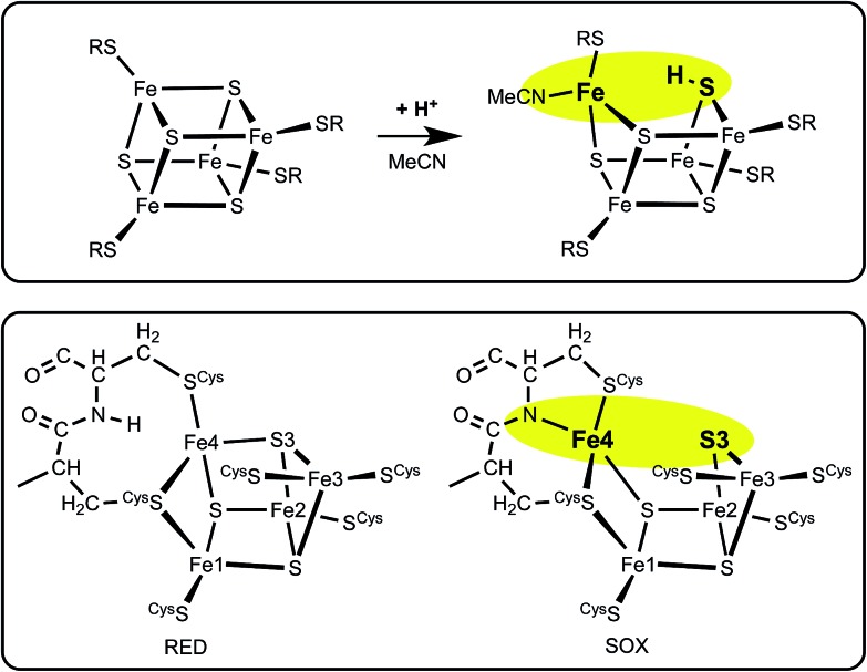
A clue to the trigger for structural change comes from recent density functional simulations (inspired by investigations of proton transfer aspects of the mechanism of nitrogenase39–41) of the acid-catalysed substitution reactions of [Fe4S4X4]2– clusters.42,43 The primary step in this catalysis is protonation of μ3-S, which causes one S–Fe bond to break leaving three-coordinate Fe plus μ-SH: the under-coordinated Fe is coordinated by solvent (acetonitrile). From this point the substitution mechanism develops in a rational fashion: a large amount of kinetic data has now been satisfactorily interpreted, based on the structural rearrangements that occur as a result of protonation of μ3-S.43 Fig. 3 outlines the calculated structural change on protonation of [Fe4S4(SR)4]2–, in comparison with the structural change in the proximal cluster. The obvious hypothesis is that protonation of S3 is involved.
Fig. 3. The similarity between the change on protonation of [Fe4S4(SR)4]2– in acetonitrile (upper panel), and the structural change RED → SOX in the proximal cluster (lower panel).
The computational methods and models used in this work are described in the ESI.† I modeled the proximal structure type computationally, first as [Fe4S3(SMe)6]3–, 2–, 1– encompassing the three core redox levels [Fe4S3]3+, 4+, 5+. In all three redox states the cluster structure closely resembles the closed geometry of the reduced proximal cluster. The closed structure of [Fe4S3(SMe)6] occurs unchanged as a local energy minimum when it is oxidised by two electrons. Using a more elaborate model, Pelmenschikov and Kaupp also recorded a local energy minimum for the closed geometry when oxidised by two-electrons.44 Subsequently, using even more complete models for the proximal cluster (ESI Fig. S4†), I have confirmed that the closed structure when oxidised by two electrons does not undergo barrierless opening, and further that the atom charges, spin densities, and interatomic distances change by remarkably small increments as the core [Fe4S3] is oxidised from charge +3 to +4 and +5 (ESI Tables T2 and T3).†
The key results for the [Fe4S3(SR)6] structure type are (1) the cluster is not opened geometrically by redox change, (2) the cluster is opened by protonation of the relevant μ3-S atom, with the Fe–S(H) distance increasing by ca. 1 Å, (3) this opening is reversed on deprotonation, and (4) this protonation behaviour is independent of the redox level of the cluster. The findings support the premise that protonation of S3 could trigger the structural change of the proximal cluster in O2-tolerant hydrogenases.
The proximal cluster as a closed protonic system
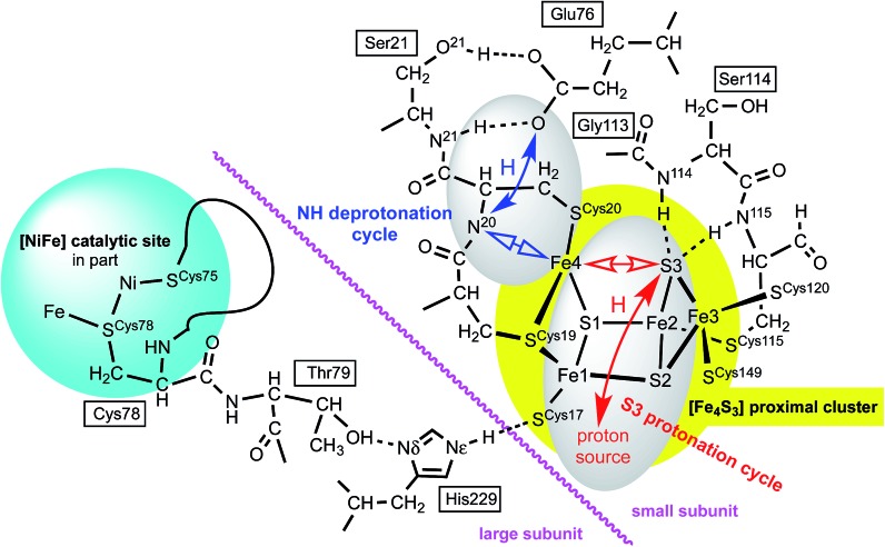
The proposed protonation of S3 to open the proximal cluster and elongate the S3–Fe4 interaction is coupled to the separate deprotonation of the peptide NH of cys20, and formation of the Fe4–N20 bond (Fig. 1). These two proton transfer cycles at the proximal cluster are named the S3 protonation cycle and the NH deprotonation cycle, as on Fig. 4. A plausible mechanism for the transfer of N20–H to the side-chain of Glu76 has been proposed, and developed with DF calculations,29,37,44 and is depicted in ESI Fig. S3.† It is not geometrically feasible for the proton released from N20–H to reach S3.
Fig. 4. Some relevant features of the model developed in this paper. Atom numbering of Re and Ec structures is used: for Hm species the link residues are Cys79, Thr80, His230. Closed arrows represent proton movements; open arrows show the movement of Fe4. The separation of the NH deprotonation cycle (blue) and S3 protonation cycle (red) is evident: details of the ‘proton source’ are described in the text.
The two catalysed reactions that occur at the Ni–Fe site, oxidation of H2 and reduction of O2, involve continuous provision of protons to or from the protein surrounds. Possible pathways for these proton transfers between the Ni–Fe catalytic site and the protein surface, and between the proximal cluster and protein surface, are evident in the protein structures and have been discussed.1,27,29,30,45 Shomura et al. 27 and Frielingsdorf et al. 30 have suggested two different proton pathways between the Ni–Fe site and the proximal cluster. However, when the enzyme is turning over with H2 only, or when it is repeatedly reactivating itself under oxic conditions (e.g. ∼2500 turnovers h–1 under 10% O2, without degradation26), a continuous stream of protons is involved, and this proton stream can only connect with external solvent. The proximal cluster and the single-proton transfer pathways between it and the Ni–Fe site could not be the source or sink for the multiple protons in reactions involving H2 or O2 at the catalytic site. The mechanisms to be developed for the proton transfer steps at the proximal cluster must be readily reversible, and it is assumed that there is no change in the total number of protons at this site during each reaction cycle: the proximal cluster is postulated to be a closed protonic system.
The linkage between the proximal cluster and Ni–Fe site
There is a direct linkage between the Ni–Fe catalytic site and the proximal cluster, illustrated in Fig. 4. One of the key cysteines bridging Ni and Fe, Cys78L, is flanked by Thr79L, which is hydrogen bonded to the Nδ atom of His229L (L and S denote the large and small protein subunits). In the protein crystal structures where no additional OH ligand was detected on Fe1, the Nε atom of His229L is hydrogen bonded to the sulfur atom of Cys17S in the proximal cluster, while in the two crystals (; 4IUB, 4IUC) containing the super-oxidised proximal cluster of Re the hydrogen bond from Nε of His229L is directed at the OH ligand on Fe1. This link, [Ni–Fe]-CysL-ThrL···HisL···[proximal cluster] occurs in all three species with crystal structures, and these residues are conserved through 19 [NiFe] hydrogenases.28 Frielingsdorf et al. report mutants with His229L substituted by alanine, methionine or glutamine, and conclude that His229L is crucial for O2 tolerance.30 The Ni–Fe catalytic site and the proximal cluster are located in the large and small sub-units respectively, with the linkage crossing between the subunits at the His229LNε hydrogen bond (Fig. 4).
Therefore it is postulated that the presence of O2 at the Ni–Fe site causes conformational changes that are transmitted through the CysL-ThrL···HisL link to the proximal cluster. A protein conformational change caused even by the ingress of O2 (larger than H2) could also be transmitted through the interface between the large and small subunits. This mechanism for initiation of events at the proximal cluster due to changes at the Ni–Fe site does not require transfer of protons between the two cluster sites.
Dual proton migrations in the proximal cluster
Preliminary calculations on the RED proximal cluster, using a model that included cysteines 17, 19 and 20 with normally protonated peptide N20–H, confirmed that endo protonation of S3 causes it to separate from Fe4, without changing the N20–H backbone, yielding three-coordinate Fe4. This means that the deprotonation of N20–H and formation of the N20–Fe4 bond are not caused by protonation of S3. The proton movements involving N20, already described by Pelmenschikov and Kaupp44 (see ESI Fig. S3†), are spatially separate from proton movements to and from S3.
The model developing from these considerations has two distinct proton transfer domains, and dual cycles, illustrated in Fig. 4. The protons involved in the NH deprotonation cycle (blue) and the S3 protonation cycle (red) are spatially separate and involve different protons. Each cycle involves bond breaking/making (open arrows) around Fe4, which is likely to control the temporal relationship between the two cycles. The NH deprotonation cycle is considered to be the same as that already described by Pelmenschikov and Kaupp,44 who did not consider protonation of S3 (ESI Fig. S3†). The analyses and simulations developed in this paper deal only with the S3 protonation cycle. Protonation of S3 in the protein can occur only in the endo conformation, in which the S3–H bond is directed towards Fe4. The alternative exo conformation for S3–H would also cause elongation of the S3–Fe4 bond, but the exo side of S3 is blocked for protonation by two well-developed peptide N–H–S3 hydrogen bonds from Cys115S and Ser114S (Fig. 4). Calculations on a model (ESI Fig. S1(a), also S4†) that included residues 115, 114, and 113 showed that the N115–H–S3 and N114–H–S3 hydrogen bonds do not control the position of S3 but do block its protonation on the exo side.
Proton source, and the role of His229
What is the source of the proton that could reach S3? The OH group found on Fe1 in oxidised Re is indicative of an OH or OH2 ligand associated with Fe1 as a possible source. This OH/OH2 ligand was not detected in crystal structures of the Hm and Ec proteins, but may be present. Should this OH or OH2 ligand be absent from the coordination sphere of Fe1 in some forms of the proximal cluster, there is indication that it could be readily formed, because all crystal structures contain a conserved water molecule located about 4.5 Å from Fe1, and there are no intervening atoms to interfere with its movement to and ligation of Fe1 (ESI Fig. S6†). This water molecule could be involved in an associative-dissociative equilibrium with Fe1, and could be a source of the proton that can move, reversibly, to S3. However, as described below, it is not necessary to use water as the proton source.
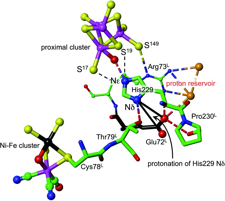
Density functional simulations of OH2 bound to Fe1 as a source of the proton to move towards S3 confirmed an expectation that as such it would be insufficiently acidic. The conjugate Fe–OH group is too basic to release a proton to the sulfide and cysteinyl sulfur atoms as would be required for protonation of S3. Nonligated water is also insufficiently acidic to protonate the proximal cluster. However, His229 that is able to hydrogen bond to this OH2/OH entity is capable of relieving the conjugate basicity of OH by provision of a proton from its Nε, particularly when pushed to do so by protonation of His Nδ. Examination of the protein structure reveals how His Nδ can be protonated. Fig. 5 depicts the relevant surroundings of His229L in structure PDB ; 4IUB, the oxidised form with OH on Fe1 and bridging O in the Ni–Fe site. The other crystal structures have the same or very similar surrounds (His229 Nε is hydrogen bonded to S17 when OH is absent). The significant structural property is the placement of the carboxylate side-chain of Glu72L close to Nδ of His229 and readily able to transfer a proton to it with minor side-chain movements. This Glu carboxylate side-chain is hydrogen bonded to two water molecules (three in PDB ; 3UQY) and to the NH2 side-chain groups of the adjacent residue Arg73L. The (H2O)2 + (–NH2) + (–NH2 +) domain so constituted can readily function as proton reservoir, and the carboxylate side-chain can easily relay a proton to or from Nδ of His229. These features of the His229 surrounds occur in the crystal structures of all of the O2-tolerant proteins. Therefore it is concluded that His229 can be readily protonated, and thereby is able to function as promoter of the acidity required to push a proton onto atoms of the proximal cluster and to S3.
Fig. 5. The surroundings of His229 in PDB 4IUB (which contains OH on Fe1 of the proximal cluster, and bridging O in the Ni–Fe site, the Ni–B state). Nε of His229 is hydrogen bonded to OH on Fe1, and is within hydrogen bonding distances of S17 (3.3 Å) and S19 (3.7 Å). Nδ of His229 is hydrogen bonded to the side-chain of Thr79L, and is near (4.2 Å, black connectors) the carboxylate side-chain atoms (red spheres) of Glu72L. These same carboxylate atoms are engaged in a hydrogen bonding network involving two water molecules (orange spheres), the side-chain NH2 groups of Arg73L, and carbonyl of Pro230L. This is the proton reservoir domain. Additional hydrogen bonds between the proton reservoir and its surrounds are not shown.
As shown in Fig. 5, Nε of His229 can hydrogen bond to the OH ligand if present, or to S17 (as observed in all other reduced and oxidised crystal structures), or, with small movement of the His229 side-chain, to S19. Further, density functional modeling shows that a water molecule can be hydrogen bonded in various geometrically favourable ways in the space between S19, S149, Nδ of His229, with or without bonding to Fe1. This propitious geometry allows a number of mechanistic hypotheses for transfer of a proton onto S19 or S149 of the proximal cluster, preparatory to continuing transfer to S3. The steps involved in these possibilities for preparatory protonation have been investigated using density functional simulation of the trajectories and transition states involved. This exploration revealed interesting relevant chemistry of the protonated cluster, including (a) aspects of the relative basicities of S149 (non-bridging thiolate), S19 (bridging thiolate), OH2 and Nε, (b) weakened ligation by protonated cysteine, (c) the ability of bridging Cys19 to reversibly unbridge from Fe4 or Fe1, and (d) the geometrical flexibility of the cysteine side-chains. These explorations of possibilities also pointed to a mechanism involving direct protonation of S19 by His229, without participation of any water present. This favourable mechanism is described in the following section: some additional results are provided in the ESI material.†
Proposed mechanism for protonation of S3
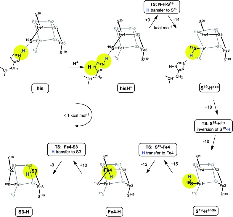
Fig. 6 shows the mechanism calculated for the transfer of a proton from His229 to S3 of the proximal cluster in its RED state. Starting with His229 hydrogen bonded to S19, the Nδ atom is protonated from the proton reservoir (intermediate hisH+). The Nε proton of His229 then transfers to S19 across a short hydrogen bond. When S19 is protonated, Cys19 changes from doubly-bridging to non-bridging coordination by breaking the S19–Fe4 bond (S19-Hexo). The H atom on S19 can then invert its configuration through a planar transition state (S19-Hinv) to S19-Hendo. This H atom then transfers to Fe4, and the S19–Fe4 bond reforms (Fe4–H). The final step is transfer of H to S3 (S3–H), with concomitant breaking of the S3–Fe4 bond. The overall H migration process is effectively energy neutral, each of the steps has an approximately symmetrical energy profile, and the intermediates are approximately equi-energetic, consistent with the requirement that this S3 protonation cycle be readily reversible. The calculated potential barriers for the steps in this mechanism, operating in both directions, range 9 to 15 kcal mol–1. Relatively small movements of the H atom are involved in some of the H transfer steps (e.g. hisH+ ↔ S19-Hexo 0.8 Å and Fe4–H ↔ S3–H 1.1 Å) and the last three steps are intramolecular, so some H atom tunneling could lower the classical barriers in this mechanism.46
Fig. 6. The mechanism proposed for migration of a proton from His229 to S3 in the RED state of the proximal cluster, with core [4Fe3S]3+. Numbers on the arrows are potential energy changes (kcal mol–1). Some atoms of the proximal cluster, and His229 in the last three intermediates, are not drawn.
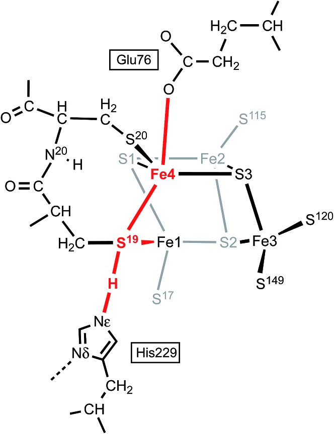
In this calculated mechanistic sequence the Cys20 amide is protonated normally throughout. The three coordination of Fe4 in the calculated structure S3–H is completed by the N20 coordination that is part of the NH deprotonation cycle. The intermediates S19-Hexo and S19-Hendo have a long S19–Fe4 distance such that Fe4 is effectively three-coordinate. This would appear to be unfavourable, but the side-chain carboxylate of Glu76S is adjacent to Fe4 (opposite S19) and readily able to complete four-coordination of Fe4 when the Fe4–S19 bond is extended. In the as-isolated and chemically oxidised crystals of EcHyd-1 (PDB ; 3USE, ; 3USC) the electron density was modeled with two conformations of the Glu76S side-chain, one of which contains an Oε–Fe4 bond.29 My calculations support the feasibility of comparable movement of the Glu76S side-chain in order to ligate under-coordinated Fe4, and reveal considerable fluxionality in the positions and bonding of the sequence of atoms Oε of Glu76, Fe4, S19, and H-Nε of His229. The entities coloured red in Scheme 2 are variable, without large barriers: thus S19 can lengthen one or the other of its bonds to Fe1 and Fe4; Fe4 can invert through its coordination plane (S1, S20, S3) towards tetrahedral stereochemistry completed by Oε of Glu76 or S19; and H of His229 moves to and from S19 as described above (see ESI Fig. S5†).
Scheme 2. The sequence of atoms and bonds (coloured red) that is fluxional in the closed form of the proximal cluster.
Further investigation and understanding of the mechanism will require more realistic simulations using larger computational models that combine the S3 protonation cycle and the NH deprotonation cycle, testing the nature of their synchronicity. The fluxionality shown in Scheme 2 will be part of the model. The Glu76S side-chain carboxylate has dual roles in transferring the N20–H proton and temporarily providing additional coordination of Fe4 when it is separated from S19. Three events are proposed to involve Fe4: (1) the breaking and making of bonds with S19 and S3 during the proton migration (Fig. 6); (2) final formation of the N20–Fe4 bond; (3) intermediate ligation of Fe4 by Oε of Glu76S. Volbeda et al. 29 constructed a QM/MM model of the proximal cluster in its open SOX form, with incorporation of a considerable number of surrounding residues in a model for putative proton transfer involving Glu76. Similar hybrid QM/MM calculations are needed to evaluate the mechanistic models I propose.
Experimental support for the proposed mechanism
The mechanism proposed relies on His229L as the provider (via Nε) of the proton that eventually reaches S3, and also on a mechanism for compensating protonation of Nδ of His229L. A proton reservoir for this purpose has been identified, and the side-chain of Glu72L is the mediator between the proton reservoir and Nδ of His229L. The recent report of the crystal structure (PDB ; 4C3O) and properties of a genetically engineered O2-tolerant [NiFe] hydrogenase from Salmonella enterica (SeHyd-5) by Bowman et al. 31 provides very strong support for these ideas. These authors identified His229 as a close neighbour of the proximal cluster, conserved in all [NiFe] hydrogenases, and therefore investigated the alanine variant, finding it to be active for oxidation of H2, but with strongly diminished O2 tolerance. Bowman et al. also noted that Glu72L (in the numbering used here: Glu73 in SeHyd-5) is conserved in most O2-tolerant hydrogenases, but is glutamine in O2-sensitive hydrogenases. They tested the alanine mutant, and found it also to be compromised with respect to O2 tolerance. In both mutants the side-chain has no acid-base capability, and their inability to provide O2 tolerance is consistent with the proposed mechanism in which both are required to have proton transfer abilities. Shomura et al. noted that this Glu72 residue is not strictly conserved in membrane bound hydrogenases, but that the contiguous Arg (see Fig. 5) is conserved.27
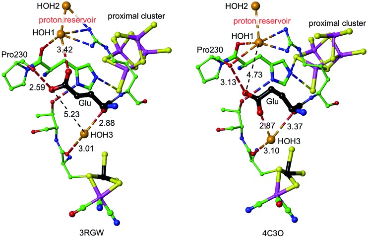
It is proposed that the Glu72L carboxylate side-chain is mobile in transferring a proton to Nδ of His229L. This is supported by the observation of different conformations of this side-chain in Re and SeHyd-5 enzymes, illustrated in Fig. 7. There is a substantial (ca. 2 Å) relocation of the Glu72 carboxylate O atoms, hydrogen bonding with the proton reservoir (; 3RGW), or folding down away from it (; 4C3O). The distances between the side-chain O atoms and Nδ of His229L are essentially the same in these two conformations, as are the abilities of the side-chain to rotate around the Cγ–Cδ bond and transfer a proton to Nδ. The ; 4C3O crystal diffraction data yielded only 3.2 Å resolution, with only 114 water molecules located, and therefore it is significant that the water molecules shown in Fig. 7 (and in the other independent molecule) were evident and refined with below-average temperature factors. The connections shown in Fig. 7 suggest also that Glu72 and HOH3 could be part of the link that communicates O2-induced changes at the Ni–Fe site to the machinery for initiation of protonation of the proximal cluster.
Fig. 7. Comparative representations of the crystal structures of 3RGW (Re) and ; 4C3O (SeHyd-5), focusing on the key His229 and Glu residues (72 in ; 3RGW, 73 in ; 4C3O, carbon atoms black) in relation to the proximal and Ni–Fe clusters (Ni black, Fe magenta), the putative proton reservoir including two water molecules, and a water molecule (HOH3) that is hydrogen bonded to O of a cysteine bridge in the NiFe site and to mainchain O of Glu. In ; 3RGW the Glu side-chain is folded up with hydrogen bonds to O of Pro230 and HOH1, while in ; 4C3O it is folded down with different hydrogen bonds to O of Pro230 and HOH3.
The model suggests further experimental tests. The hydrogen bonding protonic side chain of Arg73L supports the proton reservoir, and so variants without this ability are predicted to interfere with the proposed mechanism. The side-chain of Thr79L hydrogen bonds to His229L as part of the purported link between the Ni–Fe site and the protonation machinery at the proximal cluster: replacement with non hydrogen bonding residues could compromise the mechanism. Additional experimental tests using model systems are suggested below.
Discussion and summary
While the relationship between the major structural changes occurring at the proximal cluster and its gating of the direction and number of electrons relayed to and from the Ni–Fe active site is understood, it is the structural change at the proximal cluster that causes the appropriate electron transfers. The structural change at the proximal cluster is not simply a consequence of its change in redox state, but is the instigator of redox change. Change in geometrical structure from RED to SOX modifies also the electronic structure and the redox potentials, such that the proximal cluster can readily release two electrons to the active site where they are required to rescue the Ni–Fe cluster from its O2-induced forms that are inactive in the normal H2 oxidation cycle.
Therefore the chemical cause of the structural change RED → SOX at the proximal cluster must be questioned, and this report provides a response. It is proposed that there is a closed proton shuttle involving the μ3-S3 atom, which, when protonated to become μ-SH, breaks its bond with Fe4 and facilitates the alternative coordination of Fe4 by the ‘hard’ deprotonated backbone amide N20, concomitant with the movement of the N20 proton to the side-chain of Glu76, as described by Pelmenschikov and Kaupp.44 The idea that protonation of cluster sulfide causes disruption of cluster structure evolved from investigations of the effects of protonation of [Fe4S4X4] clusters42,43 and of simulations of similar steps at the FeMo-co cluster of nitrogenase.41 An H atom on S3 would not have been detected in the diffraction analyses of the SOX form of the proximal cluster.
It is proposed that the proton reaching S3 is from His229-Nε (or possibly from a water molecule in the vicinity of His229), being transferred first to the S of Cys19, then to Fe4, and then to S3. The potential energy profile for this trajectory of H over the RED form of the proximal cluster is accessible. Other trajectories are conceivable, but, at this stage, appear to be less favourable energetically. Both proton movements at the proximal cluster, the NH deprotonation cycle and the S3 protonation cycle, are reversible and involved in the RED ↔ SOX interconversion. They are expected to be synchronous, but details of the sequence of events in this double proton shuttle are still to be explored. Pandelia et al. 32 reported pH dependence of the RED/OX potential, with a coupled pK a of 6.9–7.1, but the identity of the species involved is unknown.
The initial proton transfer from Nε-H of His229 to S19 requires assistance through protonation of the Nδ atom of His229. A mechanism for this has been identified, involving a nearby ‘proton reservoir’ involving residues Glu72L, Arg73L, and associated water molecules. Reconformation of the acidic side-chain of Glu72L (already evident in some crystal structures) is able to deliver the proton required at His229-Nδ. This aspect of the overall mechanism is supported by some experimental observations. His229L is a fully conserved residue, and Glu72L is highly conserved. Mutation of either residue to alanine with a proton-inert side-chain compromises the O2-tolerance of the enzyme.31
One more element is required for this model, namely communication from the Ni–Fe site when it is subject to O2. There is a conserved link from one of the cysteines bridging Ni and Fe, Cys78L, through Thr79L which hydrogen bonds to His229-Nδ. Further, Glu72L is hydrogen bonded through a water molecule to CO of Cys78L. Thus, geometrical changes in the bridging region of the Ni–Fe catalytic site, caused by O2 which is believed to bind there, can be directly communicated to the His229L + Glu72L molecular machinery that initiates protonation of the proximal cluster.
In summary, the complete sequence of events involved in the triggering of O2 tolerance is envisioned as: (1) binding of O2 at the Ni–Fe bridge; (2) conformation changes transmitted through Cys78L and Thr79L to the Glu72L–Agr73L–water proton reservoir, which then (3) protonates His229-Nδ; (4) being thereby acidified, His229-Nε-H protonates S19 of the unique bridging cysteine of the proximal cluster in its RED state; (5) trigonal pyramidal S19–H inverts, to point towards Fe4, and transfers H to Fe4; (6) Fe4 (which is five-coordinate at this point), transfers H to S3 along the Fe-4–S3 bond, resulting in doubly-bridging S3–H which moves well away from Fe4; (7) at approximately the same time the N20–H proton is abstracted by the carboxylate side-chain of Glu76L, which is in proximity to Fe4 and could ligate Fe4 at earlier stages; (8) these changes in the geometric and electronic structure of the proximal cluster to that of the SOX state change its redox potential such that it can release two electrons to the Ni–Fe site and initiate the reduction of the O2-inactivated forms of the catalytic site; (9) on release of the two electrons from the proximal cluster in the SOX geometry and bonding configuration, the proton flow is fully reversed as the proximal cluster recovers its RED geometry and bonding configuration to match its RED electron count. Protons involved at the Ni–Fe catalytic site, in either the reduction of O2 (to OH2) or oxidation of H2, are postulated to be independent of the proton cycles that involve the proximal cluster. In the absence of O2 none of this molecular machinery and major geometrical change is needed, because the proximal cluster functions simply as a one-electron transfer agent involving the RED and OX states with minor geometrical adjustment.
This theory could be tested with model systems. When a synthetic cluster [Fe4S3(SR)6]z becomes available, cyclic voltammetric measurements of the z = –3/–2 and –2/–1 steps are expected to be informative. With aprotic conditions, it is predicted that standard well-separated potentials will be observed, without coupled chemical steps. Then, with stoichiometrically controlled addition of a non-coordinating Bronsted acid, it is predicted that the potentials and their separation will change, and that there will be coupled chemical events indicative of geometrical change. The expected slower rates of coupled geometrical changes, and possibly their restricted reversibility, are measureable in principle. Further, with controlled addition of a suitable ligand (non Bronsted basic), an intermediate analogous to the SOX form of the proximal cluster could be generated, to some extent replicating the chemistry (ie combination of proton transfer plus electron transfer plus ligation) proposed for the proximal cluster of O2-tolerant [NiFe] hydrogenases. However, there are complications arising from the alternative μ3-S protonation sites available in [Fe4S3(SR)6] and alternative Fe–S(H) extensions.47 In the absence of a [Fe4S3(SR)6]z model, similar experiments with readily available [Fe4S4(SR)4]z systems could be informative, see Fig. 3, remembering that the O2 sensitive enzymes possess a [Fe4S4(SR)4] cluster at the proximal position. There is a caveat here, because these model systems in solution are subject to acid-catalysed ligand substitution reactions42,43 that are unlikely to occur in the protein.
Methods
All calculations reported in this paper use Delley's DMol3 package,48–50 with numerical basis sets (dnp). The calculations are all-electron and spin unrestricted. The geometric models and the electronic states, together with method validation results and functional choice, are fully described in the ESI.†
Acknowledgments
This research is supported by the University of New South Wales, and was undertaken with the assistance of resources provided at the National Computational Facility at the Australian National University through the National Computational Merit Allocation Scheme supported by the Australian Government.
Footnotes
References
- Fontecilla-Camps J. C., Volbeda A., Cavazza C., Nicolet Y. Chem. Rev. 2007;107:4273–4303. doi: 10.1021/cr050195z. [DOI] [PubMed] [Google Scholar]
- De Lacey A. L., Fernandez V. M., Rousset M., Cammack R. Chem. Rev. 2007;107:4304–4330. doi: 10.1021/cr0501947. [DOI] [PubMed] [Google Scholar]
- Tard C., Pickett C. J. Chem. Rev. 2009;109:2245–2274. doi: 10.1021/cr800542q. [DOI] [PubMed] [Google Scholar]
- Lubitz W., Ogata H., Rüdiger O., Reijerse E. Chem. Rev. 2014;114:4081–4148. doi: 10.1021/cr4005814. [DOI] [PubMed] [Google Scholar]
- Lenz O., Ludwig M., Schubert T., Bürstel I., Ganskow S., Goris T., Schwarze A., Friedrich B. ChemPhysChem. 2010;11:1107–1119. doi: 10.1002/cphc.200901002. [DOI] [PubMed] [Google Scholar]
- Goris T., Wait A. F., Saggu M., Fritsch J., Heidary N., Stein M., Zebger I., Lendzian F., Armstrong F. A., Friedrich B., Lenz O. Nat. Chem. Biol. 2011;7:310–318. doi: 10.1038/nchembio.555. [DOI] [PubMed] [Google Scholar]
- Parkin A., Sargent F. Curr. Opin. Chem. Biol. 2012;16:26–34. doi: 10.1016/j.cbpa.2012.01.012. [DOI] [PubMed] [Google Scholar]
- Evans R. M., Parkin A., Roessler M. M., Murphy B. J., Adamson H., Lukey M. J., Sargent F., Volbeda A., Fontecilla-Camps J. C., Armstrong F. A. J. Am. Chem. Soc. 2013;135:2694–2707. doi: 10.1021/ja311055d. [DOI] [PubMed] [Google Scholar]
- Shafaat H. S., Rüdiger O., Ogata H., Lubitz W. Biochim. Biophys. Acta, Bioenerg. 2013;1827:986–1002. doi: 10.1016/j.bbabio.2013.01.015. [DOI] [PubMed] [Google Scholar]
- Fritsch J., Lenz O., Friedrich B. Nat. Rev. Microbiol. 2013;11:106–114. doi: 10.1038/nrmicro2940. [DOI] [PubMed] [Google Scholar]
- Vincent K. A., Parkin A., Armstrong F. A. Chem. Rev. 2007;107:4366–4413. doi: 10.1021/cr050191u. [DOI] [PubMed] [Google Scholar]
- Krassen H., Schwarze A., Friedrich B., Ataka K., Lenz O., Heberle J. ACS Nano. 2009;3:4055–4061. doi: 10.1021/nn900748j. [DOI] [PubMed] [Google Scholar]
- Armstrong F. A., Belsey N. A., Cracknell J. A., Goldet G., Parkin A., Reisner E., Vincent K. A., Wait A. F. Chem. Soc. Rev. 2009;38:36–51. doi: 10.1039/b801144n. [DOI] [PubMed] [Google Scholar]
- Wait A. F., Parkin A., Morley G. M., dos Santos L., Armstrong F. A. J. Phys. Chem. C. 2010;114:12003–12009. [Google Scholar]
- Friedrich B., Fritsch J., Lenz O. Curr. Opin. Biotechnol. 2011;22:358–364. doi: 10.1016/j.copbio.2011.01.006. [DOI] [PubMed] [Google Scholar]
- Murphy B. J., Sargent F., Armstrong F. A. Energy Environ. Sci. 2014;7:1426–1433. [Google Scholar]
- Kurkin S., George S. J., Thorneley R. N. F., Albracht S. P. J. Biochemistry. 2004;43:6820–6831. doi: 10.1021/bi049854c. [DOI] [PubMed] [Google Scholar]
- Lubitz W., Reijerse E., vanGastel M. Chem. Rev. 2007;107:4331–4365. doi: 10.1021/cr050186q. [DOI] [PubMed] [Google Scholar]
- Siegbahn P. E. M., Tye J. W., Hall M. B. Chem. Rev. 2007;107:4414–4435. doi: 10.1021/cr050185y. [DOI] [PubMed] [Google Scholar]
- Jayapal R., Sundararajan M., Hillier I. H., Burton N. A. Phys. Chem. Chem. Phys. 2008;10:4249–4257. doi: 10.1039/b804035d. [DOI] [PubMed] [Google Scholar]
- Galvan I. F., Volbeda A., Fontecilla-Camps J. C., Field M. J. Proteins: Struct., Funct., Bioinf. 2008;73:195–203. doi: 10.1002/prot.22045. [DOI] [PubMed] [Google Scholar]
- Ogata H., Lubitz W., Higuchi Y. Dalton Trans. 2009:7577–7587. doi: 10.1039/b903840j. [DOI] [PubMed] [Google Scholar]
- Pandelia M. E., Ogata H., Lubitz W. ChemPhysChem. 2010;11:1127–1140. doi: 10.1002/cphc.200900950. [DOI] [PubMed] [Google Scholar]
- Cracknell J. A., Wait A. F., Lenz O., Friedrich B., Armstrong F. A. Proc. Natl. Acad. Sci. U. S. A. 2009;106:20681–20686. doi: 10.1073/pnas.0905959106. [DOI] [PMC free article] [PubMed] [Google Scholar]
- Lauterbach L., Lenz O. J. Am. Chem. Soc. 2013;135:17897–17905. doi: 10.1021/ja408420d. [DOI] [PubMed] [Google Scholar]
- Wulff P., Day C. C., Sargent F., Armstrong F. A. Proc. Natl. Acad. Sci. U. S. A. 2014;111:6606–6611. doi: 10.1073/pnas.1322393111. [DOI] [PMC free article] [PubMed] [Google Scholar]
- Shomura Y., Yoon K.-S., Nishihara H., Higuchi Y. Nature. 2011;479:253–256. doi: 10.1038/nature10504. [DOI] [PubMed] [Google Scholar]
- Fritsch J., Scheerer P., Frielingsdorf S., Kroschinsky S., Friedrich B., Lenz O., Spahn C. M. T. Nature. 2011;479:249–252. doi: 10.1038/nature10505. [DOI] [PubMed] [Google Scholar]
- Volbeda A., Amara P., Darnault C., Mouesca J.-M., Parkin A., Roessler M. M., Armstrong F. A., Fontecilla-Camps J. C. Proc. Natl. Acad. Sci. U. S. A. 2012;109:5305–5310. doi: 10.1073/pnas.1119806109. [DOI] [PMC free article] [PubMed] [Google Scholar]
- Frielingsdorf S., Fritsch J., Schmidt A., Hammer M., Löwenstein J., Siebert E., Pelmenschikov V., Jaenicke T., Kalms J., Rippers Y., Lendzian F., Zebger I., Teutloff C., Kaupp M., Bittl R., Hildebrandt P., Friedrich B., Lenz O., Scheerer P. Nat. Chem. Biol. 2014;10:378–385. doi: 10.1038/nchembio.1500. [DOI] [PubMed] [Google Scholar]
- Bowman L., Flanagan L., Fyfe P. K., Parkin A., Hunter W. N., Sargent F. Biochem. J. 2014;458:449–458. doi: 10.1042/BJ20131520. [DOI] [PMC free article] [PubMed] [Google Scholar]
- Pandelia M. E., Nitschke W., Infossi P., Giudici-Orticoni M. T., Bill E., Lubitz W. Proc. Natl. Acad. Sci. U. S. A. 2011;108:6097–6102. doi: 10.1073/pnas.1100610108. [DOI] [PMC free article] [PubMed] [Google Scholar]
- Knuttel K., Schneider K., Erkens A., Plass W., Muller A., Bill E., Trautwein A. X. Bull. Pol. Acad. Sci., Chem. 1994;42:495–511. [Google Scholar]
- Roessler M. M., Evans R. M., Davies R. A., Harmer J., Armstrong F. A. J. Am. Chem. Soc. 2012;134:15581–15594. doi: 10.1021/ja307117y. [DOI] [PubMed] [Google Scholar]
- Zanello P. Coord. Chem. Rev. 1988;83:199–275. [Google Scholar]
- Dance I. Inorg. Chem. 2006;45:5084–5091. doi: 10.1021/ic060438l. [DOI] [PubMed] [Google Scholar]
- Mouesca J.-M., Fontecilla-Camps J. C., Amara P. Angew. Chem., Int. Ed. 2013;52:2002–2006. doi: 10.1002/anie.201209063. [DOI] [PubMed] [Google Scholar]
- Sharp C. R., Duncan J. S., Lee S. C. Inorg. Chem. 2010;49:6697–6705. doi: 10.1021/ic100742c. [DOI] [PubMed] [Google Scholar]
- Dance I. Dalton Trans. 2008:5977–5991. doi: 10.1039/b806100a. [DOI] [PubMed] [Google Scholar]
- Dance I. Chem. Commun. 2013;49:10893–10907. doi: 10.1039/c3cc46864j. [DOI] [PubMed] [Google Scholar]
- Dance I. Inorg. Chem. 2013;52:13068–13077. doi: 10.1021/ic401818k. [DOI] [PubMed] [Google Scholar]
- Alwaaly A., Dance I., Henderson R. A. Chem. Commun. 2014;50:4799–4802. doi: 10.1039/c4cc00922c. [DOI] [PubMed] [Google Scholar]
- Dance I., Henderson R. A. Dalton Trans. 2014;43:16213–16226. doi: 10.1039/c4dt01687d. [DOI] [PubMed] [Google Scholar]
- Pelmenschikov V., Kaupp M. J. Am. Chem. Soc. 2013;135:11809–11823. doi: 10.1021/ja402159u. [DOI] [PubMed] [Google Scholar]
- Teixeira V. H., Soares C. M., Baptista A. M. Proteins: Struct., Funct., Bioinf. 2008;70:1010–1022. doi: 10.1002/prot.21588. [DOI] [PubMed] [Google Scholar]
- Dance I. Dalton Trans. 2008:5992–5998. doi: 10.1039/b806103c. [DOI] [PubMed] [Google Scholar]
- Dance I., in preparation for publication, 2014.
- Delley B. J. Chem. Phys. 1990;92:508–517. [Google Scholar]
- Delley B., in Modern density functional theory: a tool for chemistry, ed. J. M. Seminario and P. Politzer, Elsevier, Amsterdam, 1995, pp. 221–254. [Google Scholar]
- Delley B. J. Chem. Phys. 2000;113:7756–7764. [Google Scholar]
Associated Data
This section collects any data citations, data availability statements, or supplementary materials included in this article.


