Abstract
Purpose
To explore the effect of using extremely high permittivity (εr∼1,000) materials on image quality and power requirements of spine imaging at 3 T.
Theory and Methods
A linear array of high permittivity dielectric blocks made of lead zirconate titanate (PZT) was designed and characterized by electromagnetic simulations and experiments. Their effect on the transmit efficiency, receive sensitivity, power deposition, and diagnostic image quality was analyzed in vivo in 10 healthy volunteers.
Results
Simulation results showed that for quadrature mode excitation, the PZT blocks improve the transmit efficiency by 75% while reducing the maximum 10g average specific absorption rate (SAR10) by 20%. In vivo experiments in 10 healthy volunteers showed statistically significant improvements for the transmit efficiency, and image quality. Compared to active radiofrequency shimming, image quality was similar, but the required system input power was significantly lower for quadrature excitation using the PZT blocks.
Conclusion
For single‐channel transmit systems, using high permittivity PZT blocks offer a way to improve transmit efficiency and image quality in the spine. Results show that the effect, and therefore optimal design, is body mass index and sex specific. Magn Reson Med 79:1192–1199, 2018. © 2017 The Authors Magnetic Resonance in Medicine published by Wiley Periodicals, Inc. on behalf of International Society for Magnetic Resonance in Medicine. This is an open access article under the terms of the Creative Commons Attribution NonCommercial License, which permits use, distribution and reproduction in any medium, provided the original work is properly cited and is not used for commercial purposes.
Keywords: dielectric materials, spine, 3T, transmit efficiency, receive sensitivity
INTRODUCTION
More than 25% of the total number of clinical MRI scans are performed on the spine in order to provide insight into its structural and functional integrity 1, 2. The requirement for high spatial resolution motivates clinical spine imaging at 3 T rather than 1.5T 1, 3, even though the spine is one of the regions that can suffer from a reduced transmit ( ) efficiency caused by radiofrequency (RF) wave interferences 4. As a result of these effects, dual‐transmit 3T systems have recently been introduced to reduce the general problem of inhomogeneities in body imaging by RF shimming 5, 6. Active RF shimming also improves the transmit efficiency, enabling higher tip angles in spin‐echo sequences, for example, to be achieved with associated improvements in image quality. However, the accompanying financial costs and the slow upgrade cycles of new parallel transmit technology mean that many clinical sites are still working with single‐channel transmit 3T systems.
Our aim in this work is to explore the feasibility of using very high permittivity materials as an alternative approach to dual‐transmit imaging of the spine in order to improve image quality. In previous studies, dielectric pads with a relative permittivity of ∼300 have been shown to increase the transmit efficiency and reduce the specific absorption rate (SAR) in cardiac 7, abdominal 8, 9, and cervical spine 10 applications at 3T. In the current work, materials developed by the Penn State group 11, 12, 13, 14, 15 with relative permittivity values more than three times greater than those used in previous body imaging studies are investigated. The effect of these materials on the transmit RF field, receive sensitivity, and overall diagnostic quality of the images has been analyzed. Finally, in order to place these results in the context of state‐of‐the‐art dual‐transmit systems, we compare the power efficiency, and hence SAR implications, of the dielectric approach versus dual‐transmit RF shimming.
Theory
The mode of action of dielectric materials can be illustrated by Ampère's law,
in which displacement currents ( ) within the material are given by
In the presence of an oscillating electric field, displacement currents are induced inside the dielectric that lead to a secondary magnetic field, which propagates outward from the material 16, 17. The dielectric material effectively transforms RF electric fields into RF magnetic fields, and this principle can be used to enhance the RF transmit efficiency in the region of interest if the dielectric material is designed with appropriate properties. The displacement current term in Maxwell's equations transformed to the frequency domain, , depends on the angular frequency ω, which explains why the effects of dielectric materials are substantially different at various field strengths. Many previous studies have used barium titanate suspensions with relative permittivities reaching up to 400 7, 8, 18, 19. However, recent results from other groups have suggested that materials with much higher permittivities (∼1,000) might be beneficial 11, 12, 13, 14 at 3T and might be very appropriate for the particular challenge in spine imaging 20 of producing an increase in transmit field efficiency along an extended length of the spinal column.
Methods
Dielectric Materials
Rectangular solid blocks of the piezoelectric material lead zirconate titanate (PZT; TRS Technologies, Inc, State College, PA, USA) with dimensions 70 × 25 × 90 mm3 and a weight of 1.3 kg each were used. These particular dimensions were chosen such that the blocks are not resonant at the 3T Larmor frequency, given that at resonance in thick blocks a substantial component of the magnetic energy would be contained in the dielectric material itself 21. An S11 measurement with an unmatched pick‐up loop performed on a network analyzer (E5061A; Agilent Technologies, Santa Clara, CA, USA) was used to measure the lowest resonance frequency of a single block to be at 132 MHz, corresponding to a TE01δ mode. A high‐frequency eigenmode solver (CST STUDIO SUITE; Computer Simulation Technology, Darmstadt, Germany) was used to confirm the relative permittivity as 1,075. The loss tangent of the PZT material was estimated to be δ ≈ 0.04 by measuring the quality factor of the block resonator at 132 MHz. From this, the conductivity of the PZT material was found to be around 0.38 S/m at the resonant frequency, and this value was subsequently applied in simulations at 128 MHz.
A chain of seven blocks was constructed in the foot‐head direction with 10‐mm gaps between successive blocks. Strips of copper tape were used to connect the top and bottom surfaces of the blocks at four positions per gap in order to facilitate current flow between blocks and in this way effectively merge the individual blocks into one large dielectric block. The long axes of the individual blocks were oriented in a left‐right direction in order to fully cover the width of the spine, approximately 85 mm 22. The final setup covers a total of 55 cm in the foot‐head direction.
Electromagnetic Simulations
3D Electromagnetic simulations were performed by using the finite‐difference time‐domain method (XFdtd 7.4; REMCOM, State College, PA, USA). A 16‐rung high‐pass birdcage, driven in quadrature mode, was modeled by a sinusoidal waveform feeding each capacitor gap with a phase increment of 22.5° to realize a full wavelength along the circumference of the coil. The diameter and length of the birdcage were 63 and 56 cm, respectively. An RF shield with a diameter of 70 cm and length of 120 cm was modeled around the birdcage. Female and male body models “Ella” and “Duke” from the virtual family 23 were positioned in the center of the body coil.
The PZT blocks were simulated to follow the curves of the body models so that there is an equidistant space from the body to the dielectric material along the extent of the device. A 10‐mm air gap, realized by a patient mattress in actual scanning, was inserted between the body and the dielectrics. Copper connections were modeled as strips connecting the bottom and top surfaces of blocks, bridging the 10‐mm gap between adjacent blocks.
The PZT blocks and the copper strips were given zero density to exclude them from the SAR calculations and the relative permittivity of copper was set to ε r = 1. Simulations were run at a frequency of 128 MHz on a 5‐mm isotropic grid and convergence levels were set to –45 dB. Resulting 10‐g average SAR distributions and maps were analyzed after normalization with respect to 1 W of tissue dissipated power.
MR Data Acquisition
Ten healthy volunteers (5 male and 5 female) with body mass indices (BMIs) ranging from 20.5 to 28.2 and ages ranging between 22 and 62 participated after giving informed consent. The Leiden University Medical Center Committee for Medical Ethics approved the experiments.
An Ingenia 3T dual transmit MR system (Philips Healthcare, Best, The Netherlands) was used to acquire all in vivo data. The body coil was used for RF transmission and the signal was received by the 12‐element posterior coil, which is integrated into the patient table. As is standard clinical practice, a leg cushion under the knees was used to bring the back into a flat position, in this way minimizing the distance between the posterior coil and the spine. The PZT blocks were positioned between the table and the patient mattress, creating a natural air gap of approximately 10 mm. Quadrature excitation was used to mimic a single‐channel system, and results were compared for the cases with and without blocks. Additional scans using dual‐channel RF shimming 6, 24 were acquired for further comparisons. For each configuration, T1‐ and T2‐weighted lumbar spine images, a map, and a proton‐density‐weighted image were measured in a sagittal orientation.
T1‐weighted turbo spin‐echo (TSE) scans used the following parameters: field of view (FOV) = 160 × 348 mm2; in‐plane resolution 0.8 × 1 mm2; slice thickness = 4 mm; slices = 15; echo time (TE)/ repetition time (TR)/TSE factor = 8 ms/641 ms/6; flip angle (FA) = 90°; refocusing angle = 120°; water‐fat shift = 1.5 pixels; and scan time = 2:33 min. T2‐weighted TSE scans had the following parameters: FOV = 200 × 348 mm2; in‐plane resolution 0.8 × 1.1 mm2; slice thickness = 4 mm; slices = 15; TE/TR/TSE factor = 110 ms/4,687 ms/30; FA = 90°; water‐fat shift = 0.62 pixels; and scan time = 3:26 min. When using RF shimming, the scan parameters for the T1‐ and T2‐weighted scans changed to a TR of 705 and 5,155 ms and a scan time of 2:48 and 3:47 minutes, respectively, to meet the SAR constraints.
maps were acquired using the dual refocusing echo acquisition mode method 25 (FOV = 448 × 392 mm2, in‐plane resolution = 7 × 7 mm2, slice thickness = 7 mm, slices = 40, TE1/TE2 = 1.06/2.3 ms, TR = 3.8 ms, FA = α:60º/β:10º, water‐fat shift = 0.37 pixels, and scan time = 10 seconds) and proton‐density‐weighted images were obtained using a low‐tip‐angle gradient‐echo sequence in the same geometry (TE = 1.81 ms, TR = 3.8 ms, FA = 1°, water‐fat shift = 1 pixel, and scan time = 9 seconds). Care was taken to remove all preprocessing and image filtering in the map and proton‐density‐weighted image reconstructions, so that the background noise in the proton‐density‐weighted images represents a uniform noise distribution.
Reconstructed magnitude maps were smoothed by a 3 × 3 averaging filter in MATLAB (The MathWorks, Inc., Natick, MA, USA) and normalized by the RF input power, resulting in transmit efficiency maps. Gradient‐echo‐based SNR maps were constructed by dividing the magnitude of the proton‐density‐weighted images, resulting from a sum of squares‐based coil combination, by the mean of the background noise, which was calculated in a rectangular region posterior to the spine. The mean of the noise was calculated from at least 600 pixels that do not contain signal from the body 26. The resulting gradient echo SNR maps were then further divided by the sine of the smoothed flip angle maps, yielding quantitative (with respect to the initial magnetization M 0) receive sensitivity maps according to the signal equation for low‐tip‐angle gradient‐echo sequences SI = M 0 sin(α) | | 27. Noise correlation maps were generated from pure noise samples, with noise correlation coefficients defined as
where is the noise measured in coil element i.
Two‐sided paired t tests were performed on the average power readings for all volunteers. Line graphs in the anterior‐posterior direction through the center of the FOV were produced from transmit efficiency maps and receive sensitivity maps, and average values within a predefined region of interest were tested for significant differences in additional two‐sided paired t tests. Diagnostic images were scored on image quality by two experienced MR readers that were blinded to the image acquisition types. A 1 (very bad) to 5 (excellent) grading system 5 was used in which visibility of the entire spinal column, contrast‐to‐noise ratio, SNR, and suppression of signal from the anterior part of the body were important scoring criteria. The outcomes were tested for statistical significance, which was set at P < 0.05.
Results
Electromagnetic Simulations
Figure 1 shows the magnitude of the simulated fields scaled with respect to 1 W of tissue dissipated power in the body model Duke for a chain of five, seven, and nine PZT blocks: The best results were obtained for seven blocks. Further increasing the number of blocks to nine has an adverse effect on the penetration depth of the local RF magnetic field in the body and as a consequence the homogeneity of the field degrades in the spine area. The dependence of the on the length of the effective dielectric can, in part, be related to the resonant frequencies of the different effective total lengths of the connected PZT blocks. Figure 2 shows the effect on the transmit efficiency of a wide range of permittivity values for the chain of seven PZT blocks: There is a relatively shallow optimum value around 1,000. Using a chain of seven blocks with a permittivity of 1,075 results in an increase of the transmit efficiency in the spine region of approximately 75% compared to having no blocks in place.
Figure 1.
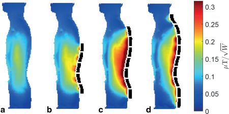
Interaction of PZT blocks with the quadrature excitation RF field. The increase in transmit efficiency varies with the number of PZT blocks (dotted black lines). Simulated fields, shown here for zero (a), five (b), seven (c), and nine (d) blocks, were normalized with respect to 1 W of tissue dissipated power. The transmit field shows the largest increase with seven connected blocks.
Figure 2.
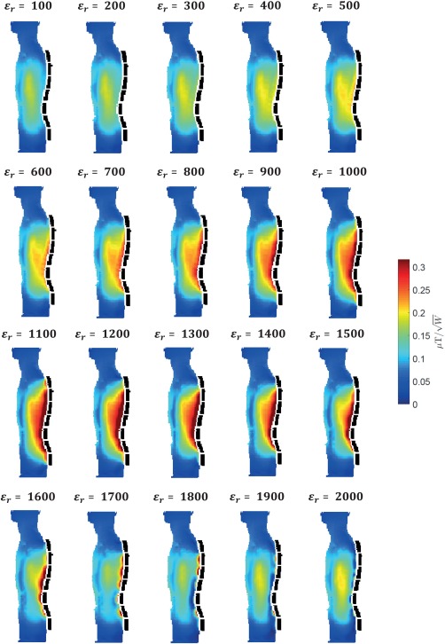
Permittivity dependence. The effect of seven PZT blocks (dotted black lines) on the transmit field is shown for a wide range of permittivity values. Simulated fields were normalized with respect to 1 W of tissue dissipated power. Conductivity values were kept constant and equal to 0.38 S/m. The transmit field has an optimal efficiency between ε r = 900 and ε r = 1,300.
Figure 3a to 3f shows the simulated transmit efficiencies and 10‐g average SAR (SAR10) maximum intensity projections without and with the chain of seven blocks present for the model Duke. Compared to the case without blocks, the high SAR10 in the arms attributed to the high electric field close to the body coil decreases by using the seven blocks array, whereas the SAR10 in the spine region increases because of the stronger electric fields around the blocks. These local increases do not limit the application, because the maximum SAR10 values (present in the arms) are decreased from 0.25 to 0.20 W/kg (20%) and peak SAR10 in the torso is decreased from 0.13 to 0.12 W/kg (8%) by using the PZT blocks. The effect of the blocks on the transmit efficiency is more pronounced in the female body model Ella than in Duke, as can be seen in Figure 3g to 3l, whereas the maximum SAR10 is decreased from 0.34 to 0.32 W/kg (6%) and the peak SAR10 in the torso is decreased from 0.18 to 0.16 W/kg (11%). The SAR results were an important prerequisite for ensuring safety in the volunteers. The Duke‐Ella difference can be related to the difference in body size, as well as differences in body composition, especially with respect to lipid distribution 7, 8.
Figure 3.
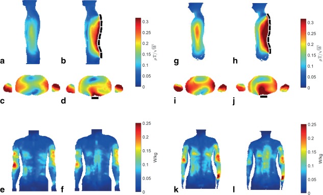
Quadrature transmit fields and specific absorption rates. Simulated fields in sagittal and transverse orientation were normalized with respect to 1 W of tissue dissipated power. The PZT blocks (schematically shown as dotted black lines) increase the transmit efficiency in the spine region compared with no blocks (a) to (d) and decrease the maximum SAR10 (e,f) in the body model Duke. The effects are similar in the body model Ella (g) to (l), but the increase in transmit efficiency is more pronounced.
Experimental Results
Figure 4a shows the measured maps in the sagittal plane normalized with respect to 1 W of input power, from quadrature mode excitation without and with PZT blocks, and from active dual‐channel RF shimming without blocks. The measurements show that, in quadrature mode, the PZT blocks increase the transmit efficiency around the spine area by approximately 75%, confirming simulations. The field anterior to the spinal column decreases. Overall, there is a much steeper posterior‐to‐anterior dropoff in the transmit efficiency with the blocks than without: This can be advantageous in that it reduces the amount of signal from the anterior anatomy, which is often the source of motion artifacts, but too steep a dropoff might result in losing important diagnostic areas. Results using RF shimming also show an increase in the transmit efficiency compared to quadrature transmission, albeit less in magnitude than with the PZT blocks, but with a reduced dropoff along the anterior‐posterior direction. The results displayed in Figure 4b show a slight increase in receive sensitivity in the cervical and sacral areas using the PZT blocks compared to the situation without blocks. Figure 4c,d shows the mean values and corresponding standard deviations along the dashed line over all 10 volunteers for the transmit efficiency and the receive sensitivity. Paired t tests executed on the field values averaged in the region of interest as defined in Figure 4b show that, in quadrature mode, the PZT blocks significantly increase the transmit efficiency compared to without blocks: P values are reported in Table 1.
Figure 4.
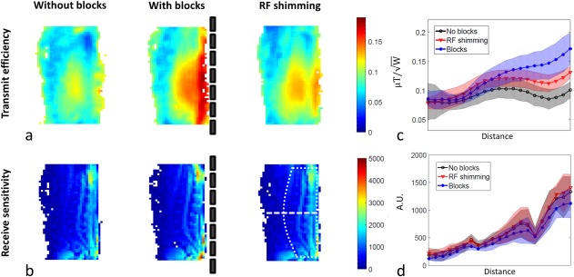
Measured transmit efficiency (a) and receive sensitivity (b) maps. maps were normalized with respect to 1 W of transmitted RF power. The blocks show an increase in transmit efficiency compared with quadrature setup without blocks. Mean values and standard deviations of the 1‐norms of the fields along the white dashed line over 10 volunteers (c,d) show that the effect is consistent and reproducible.
Table 1.
Comparison of Shimming Approaches
| No Blocks | With Blocks | RF Shimming | P 1 | P 2 | |
|---|---|---|---|---|---|
| Transmit efficiency ( ) | 0.09 ± 0.01 | 0.12 ± 0.02 | 0.11 ± 0.01 | <10−4 | 0.0009 |
| Receive sensitivity (A.U.) | 983 ± 120 | 967 ± 88 | 1017 ± 88 | 0.6773 | 0.1492 |
| T1 image quality | 3.76 ± 0.39 | 4.23 ± 0.63 | 4.53 ± 0.29 | 0.0025 | 0.1188 |
| T2 image quality | 3.89 ± 0.39 | 4.25 ± 0.53 | 4.63 ± 0.21 | 0.0053 | 0.0258 |
| Average power (W) | 252 ± 53.9 | 201 ± 27.4 | 344 ± 46.3 | 0.0124 | <10−4 |
Mean values ± standard deviations of the transmit efficiency and receive sensitivity averaged in the region of interest, of the average powers used, and of the scorings on image quality according to the 1 (very bad) to 5 (excellent) grading system. P 1 values denote the likeliness of the hypothesis and P 2 values denote the likeliness of , with values below 0.05 indicating statistically significant changes.
A.U., arbitrary units.
Noise correlation maps in Figure 5a,b and the difference matrix in Figure 5c show that the PZT blocks decrease coupling between central neighboring elements, but the average decrease in correlation coefficient of 0.01 is not statistically significant.
Figure 5.

Noise correlation analysis. Absolute values of the noise correlation coefficients of the 12‐element posterior coil without blocks (a) and with blocks (b). The difference map (c), with an average difference in noise correlation coefficient of –0.01, shows no systematic changes. (d) Schematic overview of the orientation of the separate coil elements.
Figure 6 shows T1‐ and T2‐weighted images for 1 male and 1 female volunteer. Both the T1‐weighted and T2‐weighted images show a reduced signal intensity anterior to the spine compared to the reconstructed images acquired without blocks. This effect is a direct consequence of the steep posterior‐to‐anterior gradient. The more global effect of active RF shimming of the transmit field is apparent in the third column of Figure 6, where higher signal is visible anterior to the spine. The passive dielectric shimming approach and active RF shimming both result in a larger effective FOV in the foot‐head direction compared with the quadrature setup without blocks. In contrast to results from male volunteers, some of the female volunteer results also show regions of overtipping close to the dielectric material, caused by the very large and very local increase in transmit efficiency that was shown by simulation to be higher in the female model than in the male model. Overall, the PZT blocks improved the T1 and T2 scorings in 9 of 10 and 8 of 10 of the scanned volunteers, respectively. The two volunteers that did not show improvement were male volunteers with BMIs of 28.7 and 20.8. The low BMI case was characterized by a posterior‐to‐anterior dropoff in signal intensity, which was very close to the anterior part of the spinal column. Overtipping in the subcutaneous fat was not considered a limiting factor. Table 1 confirms that image quality is improved significantly (P = 0.0025 and P = 0.0053 for T1‐ and T2‐weighted images, respectively) when using PZT blocks versus without, and that image quality is similar to the one obtained with active RF shimming (P = 0.1188 and P = 0.0258 for T1‐ and T2‐weighted images, respectively).
Figure 6.
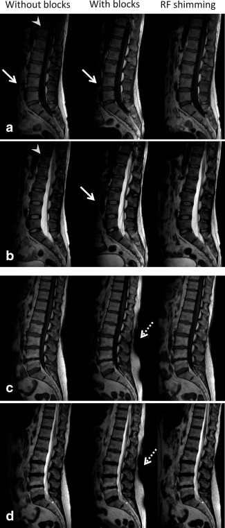
Effect on diagnostic image quality. T1‐ (a) and T2‐weighted (b) lumbar spine images without and with blocks with the system in quadrature mode and with active RF shimming. The PZT blocks in combination with the quadrature excitation RF field result in an overall increase in image quality with respect to no blocks. The improvement achieved by blocks is similar to the actively RF shimmed result, except for the dropoff in signal anterior to the vertebrae (solid arrows), which is also visible in the T1‐weighted images obtained with quadrature excitation without blocks. Both blocks and active RF shimming result in an enlarged FOV in the foot‐head direction (arrowheads) compared with quadrature setup without blocks. T1‐ (c) and T2‐weighted (d) images in female volunteers occasionally show overtipping in regions close to the PZT blocks (dashed arrows). The effect of the confined transmit field when using passive dielectric shimming clearly comes forward in this volunteer. Small geometrical variations were introduced because of patient reposition when placing the PZT blocks. Average images scores are: (a) 4 – 5 – 4.75; (b) 3.75 – 4.5 – 4.75; (c) 4.25 – 5 – 4.75; and (d) 4.5 – 5 – 5.
It has been noted previously that RF shimming generally uses more power than quadrature excitation in order to obtain a more homogeneous field 28. Figure 7 and Table 1 show that passive dielectric shimming with the PZT blocks needs significantly lower average power (P < 10−4) compared with active RF shimming.
Figure 7.
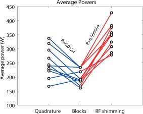
Power distributions. Average input powers for the T1‐ and T2‐weighted scans for all volunteers. Two sided paired t tests show a significant decrease in average power when using the PZT blocks. Active RF shimming uses extra power to obtain a homogeneous distribution along with the desired level.
Discussion
EM simulations and the in vivo data acquired in this study confirm that very high permittivity ceramic blocks, made of lead zirconate titanate, can be used to increase the transmit efficiency in the spine at 3T. The small enhancement in receive sensitivity of the phased array, in combination with the focused transmit profile, results in higher SNR in the spine region, leading to an increased image quality compared to quadrature operation without blocks. The steeper dropoff in SNR in the image in the anterior‐posterior direction reduces potential image artifacts originating from motion in the anterior abdomen. This posterior‐to‐anterior signal dropoff should not be too steep and future designs should carefully take into account the diagnostic quality in the entire anatomy of interest. However, in this study we did not observe signal voids from the spinal cord itself attributed to the blocks.
It should be noted that the default clinical settings use a transverse slice in the foot‐head direction of the imaging FOV for the power optimization and optimize the integrated signal over this slice as a function of tip angle. As shown, the transmit field is highly inhomogeneous and so the power optimization procedure (which is more suitable to 1.5T) is highly dependent upon the homogeneity. When the PZT blocks are used, as outlined above, the posterior‐to‐anterior dropoff in the transmit field is much greater than in the actively RF shimmed case, and therefore the transmit field homogeneity within an entire transverse slice (including the signal from the abdomen) is lower. Power optimization is “biased” toward the higher transmit efficiencies close to the posterior of the subject, leading to overtipping in some subjects and, in general, to a much lower effective tip angle in the spinal column than would be optimal. This situation is much less severe for the actively RF shimmed case, where more optimal tip angles are achieved. An improved tip angle calibration procedure would counter this discrepancy and realize optimal SNR with PZT blocks.
Another question that we have started to address is whether the passive dielectric shimming approach is as good as active RF shimming. This was the case in a previous report on cardiac imaging 7, using materials with a much lower permittivity. The advantages of passive dielectric shimming include the equal power distribution between the separate transmit channels, the reduced RF input power, and the slightly enhanced receive sensitivity. Whereas RF shimming drives the system to its hardware limits by allowing for amplitude differences between channels, potentially leading to peak power problems, passive dielectric shimming does the opposite: The PZT blocks improve the transmit efficiency whereas the quadrature power distribution is maintained. The advantages of active RF shimming over passive dielectric shimming are its ease of handling and, most important, its patient‐adaptive nature, that is, a “one‐size‐fits‐all” approach. For example, in some female volunteers, the local effect of the PZT blocks produced overtipping in the subcutaneous fat in the TSE sequences. Although not strictly relevant for clinical diagnosis, this is a distracting feature for radiologists and also indicates that optimal tip angles may not be achieved in the region of interest. If patient size or body composition vary too much, a different set of blocks might be optimal. Active RF shimming does not suffer from this disadvantage, because the adjustments are patient specific. Further research is needed to compare the performance of passive dielectric shimming and active RF shimming in terms of image contrast and potential motion artifacts in real patients. However, in order to perform a rigorous comparison, a number of important changes to the power optimization protocol on the clinical scanner are needed. To obtain maximum SNR in the spinal column, power optimization on the localized 3D volume of the spinal column would need to be performed.
Limitations to this study are the fact that only two body models have been simulated and only one was used for optimization of the number of blocks, the size of the air gap, and the overall structure of the device. Insights gained during this study into the effect of the blocks for different BMIs offer some motivation for a more patient‐specific design. Because of the current limitations in the production and availability of these specialized ceramics, only specific dimensions and permittivities could be used. Hence, different from studies using suspensions of metal titanates, this fact reduces the degrees of freedom in the design of the blocks. Future work can be performed to optimize material parameters in different designs.
In conclusion, this study has shown the feasibility of “upgrading” single‐channel transmit hardware at 3T with high permittivity PZT blocks to support spine applications. Image quality is significantly improved and power deposition is reduced with respect to a basic quadrature setup.
REFERENCES
- 1. Vertinsky AT, Krasnokutsky M V, Augustin M, Bammer R. Cutting‐edge imaging of the spine. Neuroimaging Clin N Am 2007;17:117–136. [DOI] [PMC free article] [PubMed] [Google Scholar]
- 2. Ghanem N, Uhl M, Brink I, Schäfer O, Kelly T, Moser E, Langer M. Diagnostic value of MRI in comparison to scintigraphy, PET, MS‐CT and PET/CT for the detection of metastases of bone. Eur J Radiol 2005;55:41–55. [DOI] [PubMed] [Google Scholar]
- 3. Tanenbaum LN. Clinical 3T MR imaging: mastering the challenges. Magn Reson Imaging Clin N Am 2006;14:1–15. [DOI] [PubMed] [Google Scholar]
- 4. Dietrich O, Reiser MF, Schoenberg SO. Artifacts in 3‐T MRI: physical background and reduction strategies. Eur J Radiol 2008;65:29–35. [DOI] [PubMed] [Google Scholar]
- 5. Willinek WA, Gieseke J, Kukuk GM, Nelles M, König R, Morakkabati‐Spitz N, Träber F, Thomas D, Kuhl CK, Schild HH. Dual‐source parallel radiofrequency excitation body MR imaging compared with standard MR imaging at 3.0 T: initial clinical experience. Radiology 2010;256:966–975. [DOI] [PubMed] [Google Scholar]
- 6. Ibrahim TS, Lee R, Baertlein BA, Abduljalil AM, Zhu H, Robitaille PML. Effect of RF coil excitation on field inhomogeneity at ultra high fields: a field optimized TEM resonatior. Magn Reson Imaging 2001;19:1339–1347. [DOI] [PubMed] [Google Scholar]
- 7. Brink WM, Webb AG. High permittivity pads reduce specific absorption rate, improve B1 homogeneity, and increase contrast‐to‐noise ratio for functional cardiac MRI at 3 T. Magn Reson Med 2014;71:1632–1640. [DOI] [PubMed] [Google Scholar]
- 8. De Heer P, Brink WM, Kooij BJ, Webb AG. Increasing signal homogeneity and image quality in abdominal imaging at 3 T with very high permittivity materials. Magn Reson Med 2012;68:1317–1324. [DOI] [PubMed] [Google Scholar]
- 9. Franklin KM, Dale BM, Merkle EM. Improvement in B1‐inhomogeneity artifacts in the abdomen at 3T MR imaging using a radiofrequency cushion. J Magn Reson Imaging 2008;27:1443–1447. [DOI] [PubMed] [Google Scholar]
- 10. Yang QX, Rupprecht S, Luo W, et al. Radiofrequency field enhancement with high dielectric constant (HDC) pads in a receive array coil at 3.0T. J Magn Reson Imaging 2013;38:435–440. [DOI] [PMC free article] [PubMed] [Google Scholar]
- 11. Rupprecht S, Sica CT, Sahul R, Kwon S, Lanagan MT, Yang QX. Drastic enhancement and manipulation of RF field with ultra high dielectric constant (UHDC) material at 3T. In Proceedings of the 21st Annual Meeting of ISMRM, Salt Lake City, Utah, USA, 2013. p. 396.
- 12. Cao Z, Luo W, Sica CT, Oh S, Rupprecht S, Carluccio G, Collins CM, Yang QX. Dramatic improvement of parallel imaging with high dielectric material—demonstration with electromagnetic field calculations at 123 MHz. In Proceedings of the 21st Annual Meeting of ISMRM, Salt Lake City, Utah, USA, 2013. p. 2802.
- 13. Sica C, Luo W, Rupprecht S, Lanagan MT, Collins CM, Sahul R, Kwon S, Yang QX. Ultra high dielectric constant (uHDC) head insert at 3T for dramatic reduction of SAR and B1 + inhomogeneity. In Proceedings of the 22nd Annual Meeting of ISMRM, Milan, Italy, 2014. p. 8045.
- 14. Rupprecht S, Lee B, Zhu X, Chen W, Yang QX. Signal‐to‐noise ratio improvement for MR proton spectroscopy at 3T using a ultra high dielectric constant (uHDC) material sleeve. In Proceedings of the 22nd Annual Meeting of ISMRM, Milan, Italy, 2014. p. 5458.
- 15. Vaidya M V, Chen G, Zhang B, Collins CM, Sodickson DK, Lattanzi R. Effect of an annular sleeve of high permittivity material on resonant modes and homogeneity of a birdcage coil. IEEE Int Symp Biomed Imaging 2015;12:1077–1080. [Google Scholar]
- 16. Webb AG. Dielectric materials in magnetic resonance. Concepts Magn Reson Part A 2011;38A:148–184. [Google Scholar]
- 17. Brink WM, Remis RF, Webb AG. A theoretical approach based on electromagnetic scattering for analysing dielectric shimming in high‐field MRI. Magn Reson Med 2016;75:2185–2194. [DOI] [PubMed] [Google Scholar]
- 18. Brink WM, van der Jagt AM, Versluis MJ, Verbist BM, Webb AG. High permittivity dielectric pads improve high spatial resolution magnetic resonance imaging of the inner ear at 7 T. Invest Radiol 2014;49:271–277. [DOI] [PubMed] [Google Scholar]
- 19. Brink WM, Versluis MJ, Peeters JM, Börnert P, Webb AG. Passive radiofrequency shimming in the thighs at 3 T using high permittivity materials and body coil receive uniformity correction. Magn Reson Med 2016;76:1951–1956. [DOI] [PubMed] [Google Scholar]
- 20. Hooijmans MT, Dzyubachyk O, Nehrke K, Koken P, Versluis MJ, Kan HE, Börnert P. Fast multistation water/fat imaging at 3T using DREAM‐based RF shimming. J Magn Reson Imaging 2015;42:217–223. [DOI] [PubMed] [Google Scholar]
- 21. Bluemink JJ, Raaijmakers AJ, Koning W, Andreychenko A, Rivera DS, Luijten PR, Klomp DWJ, van den Berg CA. Dielectric waveguides for ultrahigh field magnetic resonance imaging. Magn Reson Med 2016;76:1314–1324. [DOI] [PubMed] [Google Scholar]
- 22. Zhou SH, McCarthy ID, McGregor AH, Coombs RR, Hughes SP. Geometrical dimensions of the lower lumbar vertebrae‐‐analysis of data from digitised CT images. Eur Spine J 2000;9:242–248. [DOI] [PMC free article] [PubMed] [Google Scholar]
- 23. Christ A, Kainz W, Hahn EG, et al. The virtual family—development of surface‐based anatomical models of two adults and two children for dosimetric simulations. Phys Med Biol 2010;55:N23–N38. [DOI] [PubMed] [Google Scholar]
- 24. Hoult DI, Phil D. Sensitivity and power deposition in a high‐field imaging experiment. J Magn Reson Imaging 2000;12:46–67. [DOI] [PubMed] [Google Scholar]
- 25. Nehrke K, Börnert P. DREAM—a novel approach for robust, ultrafast, multislice B1 mapping. Magn Reson Med 2012;68:1517–1526. [DOI] [PubMed] [Google Scholar]
- 26. Dietrich O, Raya JG, Reeder SB, Reiser MF, Schoenberg SO. Measurement of signal‐to‐noise ratios in MR images: influence of multichannel coils, parallel imaging, and reconstruction filters. J Magn Reson Imaging 2007;26:375–385. [DOI] [PubMed] [Google Scholar]
- 27. Wang J, Qiu M, Yang QX, Smith MB, Constable RT. Measurement and correction of transmitter and receiver induced nonuniformities in vivo. Magn Reson Med 2005;53:408–417. [DOI] [PubMed] [Google Scholar]
- 28. Brink WM, Gulani V, Webb AG. Clinical applications of dual‐channel transmit MRI: a review. J Magn Reson Imaging 2015;42:855–869. [DOI] [PubMed] [Google Scholar]


