Abstract
We experimentally demonstrate a fine control over the coupling strength of vibrational light–matter hybrid states by controlling the orientation of a nematic liquid crystal. Through an external voltage, the liquid crystal is seamlessly switched between two orthogonal directions. Using these features, for the first time, we demonstrate electrical switching and increased Rabi splitting through transition dipole moment alignment. The C−Nstr vibration on the liquid crystal molecule is coupled to a cavity mode, and FT‐IR is used to probe the formed vibropolaritonic states. A switching ratio of the Rabi splitting of 1.78 is demonstrated between the parallel and the perpendicular orientation. Furthermore, the orientational order increases the Rabi splitting by 41 % as compared to an isotropic liquid. Finally, by examining the influence of molecular alignment on the Rabi splitting, the scalar product used in theoretical modeling between light and matter in the strong coupling regime is verified.
Keywords: cavity quantum electrodynamics, liquid crystals, polarization, quantum chemistry, vibrational polariton
Strong light–matter interactions have come into the spotlight in recent years, as a means of modifying molecular properties by tuning of their electromagnetic environment. The phenomenon has been demonstrated for organic/inorganic molecules,1, 2, 3, 4, 5 nanographene,6 monolayer transition metal dichalcogenides,7, 8 proteins,9 chlorosomes,10 single‐wall carbon nanotubes,11 single molecules12 and even within living organisms.13 Applications of strongly coupled systems so far comprise polariton lasing14 and superfluidity,15 efficient second harmonic generation,16 room temperature Bose–Einstein condensates,17, 18 conductivity enhancement19 and quantum information processing.20 Although strong coupling (SC) of electronic transitions has been studied for many years, SC of molecular vibrational modes in the IR has just begun to be investigated.21, 22, 23, 24, 25, 26, 27, 28 Applications of SC in chemistry are only in their infancy, however it has already been shown that formation of these hybrid states can lead to alteration of physical and chemical properties of molecules.29, 30, 31 Other recent achievements include demonstration of changes in photochemical properties,32 energy transfer rates,33, 34 chemical reactivity,35 Raman scattering enhancement,36 and Stokes shift control.37 Furthermore, pioneering theoretical works predict suppression of photochemical reactions, order of magnitude enhancement of electron transfer, or even breaking the Stark–Einstein law.38, 39, 40, 41
This work builds on the original atom‐quantized radiation interaction model introduced by E. T. Jaynes and F. W. Cummings in 1963,42 describing an oscillatory exchange of energy between an excited state and a resonant confined electromagnetic (EM) field. In the strong coupling limit, the exchange of energy is larger than any dissipation process and becomes irreversible.43, 44 As a consequence, the excitation becomes delocalized and the original resonant energy levels are split into higher and lower polaritonic states, separated in energy by the so‐called Rabi splitting ( ; Figure 1 a). Modeling can be done with different theoretical frameworks (from fully classical to fully quantum)45 but all of these require light–matter interaction. Ideally, this interaction occurs between the transition dipole moment of the molecule and the electric component of the EM field. The strength of the molecule‐field coupling depends on the angle between the transition dipole moment and the cavity electric field [Figure 1 b; Eq. (1)].
| (1) |
Figure 1.
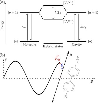
a) Jablonski diagram of a vibrational transition at energy ( ), strongly coupled to an optical cavity mode ( ) at energy giving new hybrid vibro‐polaritonic states and , with an energy separation (the Rabi‐splitting). b) Angle between the electrical dipole moment of the incident light and the orientation of the transition dipole moment associated with the coupled state of the molecule. Also shown is the molecule used in this study (5CB, R=pentyl), which has a C≡n stretch vibration in the long axis direction of the molecule.
Here, we report that vibrational strong coupling can be enhanced and tuned by controlling the orientation of orientationally ordered molecules inside a Fabry–Pérot cavity. We make use of a nematic liquid crystal (LC), which is a uniaxial three‐dimensional anisotropic liquid. The local average direction of the rod‐like molecules, the director , can be uniformly aligned in thin cavities by means of defined boundary conditions. Furthermore, the director can be easily reoriented by means of an external voltage through the dielectric torque. Using these features, we demonstrate electrical switching and increased Rabi splitting through transition dipole moment alignment. Also, we verify the angular dependence of the transition dipole moment and the electrical component of the electromagnetic field, as predicted in Equation (1).
Fabry–Pérot cavities containing the well‐known liquid crystal (LC) 4′‐pentyl‐4‐biphenylcarbonitrile (5CB, cf. Figure 1 b) having a nematic phase at room temperature was used (the clearing point of 5CB is 35 °C). In the absence of an external voltage the LC director is uniformly aligned parallel to the cavity walls by means of homogeneous planar boundary conditions (a rubbed polymer layer). In order to relate molecular orientation to transition dipole moment orientation, we chose to couple the CN stretch vibration, which is exactly parallel to the molecular long axis in 5CB.46 Furthermore, 5CB has positive dielectric anisotropy, and when a sufficiently high voltage is applied between the cavity walls the director switches from parallel to essentially perpendicular to the cavity plane (Figure 2 a). At moderate voltages the director field changes smoothly along the cell normal, with the largest reorientation in the middle between the plates. The cavity (Figure 2 b, Supporting Information Figures S1–S2) was made from ITO–gold electrode/mirrors on IR‐transparent CaF2 substrates (see materials and methods section for details). A linear polarizer was placed in front of the 5CB cavity to set the light polarization to be parallel or perpendicular to the LC director, respectively (Figure 2 c). All experiments were conducted at normal incidence to the LC‐cell.
Figure 2.
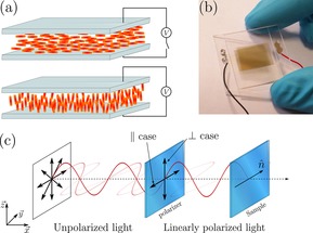
a) Orientation of the molecules (5CB) inside the cavity with or without an applied voltage. 5CB is in a nematic phase at room temperature. b) Photograph of a processed cavity. c) Measurement geometry configuration between the incident polarized light and the given director vector of the liquid crystal.
From the transmission spectrum of the empty cavity, we estimated the optical mode quality factor Q to be 112 (14th cavity mode) before filling with 5CB (full width half maximum FWHM=22 cm−1; Figure 3 a). The CN stretch vibration in 5CB is located at 2226 cm−1, and is relatively sharp (FWHM=10 cm−1; upper curve in Figure 3 a). Thus, the width of the vibrational transition roughly matches that of the cavity optical modes. In order to observe vibrational strong coupling the resonance frequency of the cavity must be precisely tuned to the CN stretch vibration. The nominal thickness of the LC‐cell was governed by 32 μm thick spacers separating the cavity walls. To fine tune the thickness, and thus the cavity resonance frequency, a sample holder with the ability to put mechanical pressure over the LC‐cell was constructed (Figure S7). When mechanical pressure is applied to the cavity, the resonant frequency is shifted (Figure 3 b,c,d). Nematic LCs are optically anisotropic, that is, the refractive index is different for the polarization of light being parallel or perpendicular to the director ( and ). The orientational order is however, not perfect, and the molecule′s long axis fluctuates about the director. This means that the CN stretch will have components along and perpendicular to the director. In Figure 3 b,c the spectral shift towards higher wavenumber due to compression of the cavity is 45 cm−1 and 34 cm−1 for interrogation with probe light with parallel and perpendicular polarization relative to the director. This corresponds to a compression of ≈1 μm (this is not an upper limit for pressure tuning the cavity resonance). At resonance of the optical mode of the cavity with the absorption band of the CN stretch, we observe a spectral splitting inside the cavity of 57 and 32 cm−1 for probe light with parallel and perpendicular polarization relative to the director, respectively (Figure 3 b–d). For each case, the energy separation is greater than both the FWHM of the cavity and the molecular resonance and the vibrational strong coupling regime is reached. Furthermore, with the mechanical tuning mechanism we could tune the cavity to resonance for any voltage‐controlled director configuration.
Figure 3.
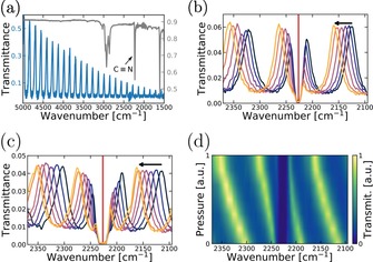
a) Transmittance spectrum of an empty cavity in blue and ATR spectrum of 5CB in black grey. b, c) Transmittance spectra of a filled cavity in parallel and perpendicular polarization, respectively, with an increased amount of mechanical pressure over the cavity. The arrow indicates the shift direction when mechanical pressure is applied. Red line indicates the absorption maximum of 5CB. d) Re‐plot, of b) showing the shift in transmittance according to the pressure applied.
The Rabi splitting when probing the cell using in‐plane polarized light parallel to the director of the cell is 57 cm−1. When applying an external voltage over the cell, the splitting decreases from 57 to 39 cm−1 (Figure 4 a, Figure S4). Using in‐plane polarized light perpendicular to the director of the cell, the splitting at 0 V is smaller (32 cm−1), and no change in splitting is observed with applied voltage (Figure 4 c, Figure S5). These observations can be understood from the geometrical configuration of the system (Figure 4 d) and from Equation (1). When applying an external voltage across the cavity mirrors, the molecules reorient, from a planar to a homeotropic alignment (Figure 2 a). Since the optical mode is polarized along the plane, this reduces the scalar product in Equation (1) and provides a means of tuning light–matter interaction strength by applied potential. The Frédericksz transition (i.e. the threshold at which the director of the LC begins to twist) occurs at 2 V (AC; Figure S3). For probe polarization in‐plane and parallel to the director, the 5CB transition dipole moment is aligned for maximum interaction with the incident light, but upon applying potential it rotates to be perpendicular, minimizing interaction. For probe polarization in‐plane but perpendicular to the director, the 5CB transition dipole moment is always perpendicular to the incident light, both before and after switching. Therefore, the Rabi splitting is independent of the external voltage for that case.
Figure 4.
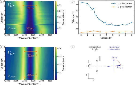
a, c) Transmittance map of a filled cavity with respect to the voltage applied for parallel and perpendicular polarization, respectively. b) Rabi‐splitting as a function of applied voltage over the cavity monitoring with the polarizer parallel (blue) or perpendicular (orange) to the alignment layer. d) Side view of the cell, where the polarization direction of the light can be compared to the molecular orientation with or without an applied voltage.
The reduction in the Rabi‐splitting from the maximum using voltage tuning is not as large as that observed by rotating the probe polarization perpendicular to the director (39 vs. 32 cm−1), which can be due to the fact that the director at the surfaces does not switch. Hence, even at the highest applied voltages, when the director is essentially normal to the cavity in the bulk of the cavity there are thin regions in the vicinity of the alignment layers in which the director is still parallel to the cavity. Moreover, by extrapolating the isotropic absorbance from Figure 5 ( , the Rabi‐splitting for an isotropic phase can be calculated (40 cm−1) and gives the same value for measured splitting (Figure S6). Therefore, we were able to reversibly modulate the strength of the Rabi‐splitting from significantly less than (39 cm−1) to significantly more than (57 cm−1) that of an isotropic system by E‐field induced change in the orientation of the molecules inside the cavity.
Figure 5.
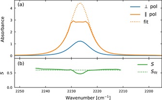
a) Absorbance spectra of aligned 5CB molecules with parallel (orange) and perpendicular (blue) orientation to the incident polarized light. Solid orange curve is raw data and the dotted curve is a fit using perpendicular polarization to extrapolate high absorbances. b) Order parameter of 5CB calculated using Equation (2) and data from Figure 5 a.
To verify the dependence of the Rabi splitting on the relative direction of the 5CB transition dipole moment and as predicted by Equation (1), the average angle between the liquid crystal molecular axis and the director vector first needs to be determined. The angle can be calculated through the order parameter S of the LC, which is given by Equation (2):46
| (2) |
where, d is the dichroic ratio, β the angle between the long axis and the dipole moment (β=0 for the CN stretch vibration in 5CB) and, g, the correction factor due to the anisotropy of the local field of the incident light. Using the literature value for the correction factor46 (g=1.50), and data from Figure 5 a, the order parameter was obtained (S=0.60, in agreement with the reported value in literature46, at 25 °C) using Equation (2). Furthermore, from Equation (3) the tilt angle (θ) of the LC (assuming a unimodal delta distribution around the tilt angle) was determined to 31.2 degrees.47
| (3) |
Inserting this value in Equation (1) for both the parallel and perpendicular configurations, gives a predicted ratio of the Rabi splitting between the two cases [Eq. (4)].
| (4) |
The ratio of the measured Rabi splitting for the two configurations is 1.78 (Figure 4 d), thus in very good agreement with the predicted one. Furthermore, the Rabi splitting has been determined to follow a square root dependence on the molecular concentration. By assuming that the concentration is linearly dependent to the concentration, this is verified through Equation (5) (Absorbances at 2226 cm−1):
| (5) |
The agreement between the predicted and observed values confirms the excellent voltage and probe polarization control of strong light–matter interactions in these systems.
In conclusion we have demonstrated vibrational strong coupling between a cavity mode and an anisotropic liquid. The nematic phase liquid crystal employed allowed for in situ tuning of the Rabi splitting by applying an external voltage across the cavity. To our knowledge, this is the first example of AC electrical field switching in the strong coupling regime. The results are of importance for future applications where fine tuning of vibrational strong coupling is required, and provides a first step towards switchable polariton emission. Furthermore, the orientation dependence of light–matter coupling in the strong coupling regime was examined, giving experimental verification of present theoretical models.
Experimental Section
Cavity fabrication
CaF2 substrates were cleaned by carefully wiping them with acetone and isopropanol, and dried with nitrogen. Then, 100 nm of indium‐tin oxide (ITO), In2O3‐SnO2 90–10 wt % (Testbourne Ltd) was deposited on the cleaned calcium fluoride substrates (Raman grade CaF2, Crystran Ltd) using a DC magnetron sputter deposition system (Hex, Korvus Technology) at a deposition rate of 1.07 Å s−1. CaF2 substrates were patterned during ITO deposition with an aluminium mask in order to avoid electrical shortcuts. Substrates were then baked on a 400 °C hot plate for 1 hour. Thereafter, 7 nm of gold was deposited on top of the ITO at a deposition rate of 2.67 Å s−1. In a clean environment, 20 nm of 0.1 % polyimide (PI2610) dissolved in DMSO was then spin‐coated at 5000 rpm for 30 seconds on the substrates. A soft bake at 100 °C for one minute was done before curing in a convection oven at 300 °C for 3 hours with a ramp rate of 4 °C min−1 in order to obtain an insoluble polyimide film and to remove residual solvent. The substrates were rubbed unidirectionally in a buffing machine (LC‐tec AB, Borlänge, Sweden) using a velvet cloth in order to give a boundary condition for the self‐alignment to the LC. Two substrates were sealed together to form a cavity using a glue dispensing system (Asymtek 402) with an optical adhesive (Norland Optical Adhesive 68, Thorlabs). The thickness of the cavity was set with 32 μm PMMA spacers (Cospheric LLC) mixed directly within the glue (Figure S2). The two substrates were pressed together using a vacuum packer (Multivac AB) and cured under UV illumination for 45 seconds, 1 minute relaxation (without vacuum) and 9 min for curing entirely the glue. Electrical wires were soldered using silver conductive paste (Sigma Aldrich) which was dried for 45 minutes on a hot plate at 100 °C. The cavity was finally filled at room temperature with 5CB (4′‐pentyl‐4‐biphenylcarbonitrile, Sigma Aldrich).
Cavity characterization
The spectra of the cavity were recorded by standard FTIR (Bruker IFS 66v/S) in transmission mode using a polarizer. All measurements were performed with a resolution of 2 cm−1 and averaged over 64 scans.
For switching the liquid crystal inside the cavity, a square signal of 1 kHz was generated with a signal generator, and voltage measurements were acquired peak to peak using an oscilloscope. Tuning of the cavity was performed by mechanically pressing the cavity in a homemade sample holder (3D printer).
Conflict of interest
The authors declare no conflict of interest.
Supporting information
As a service to our authors and readers, this journal provides supporting information supplied by the authors. Such materials are peer reviewed and may be re‐organized for online delivery, but are not copy‐edited or typeset. Technical support issues arising from supporting information (other than missing files) should be addressed to the authors.
Supplementary
Acknowledgements
K.B. gratefully acknowledges the financial support of the Swedish Foundation for Strategic Research (ICA14‐0018) and the Ragnar Söderberg Foundation. T.E. acknowledges financial support from Agence Nationale de Recherche. Bo Albinsson is acknowledged for providing access to FT‐IR spectrophotometer and MyFab for free cleanroom access.
M. Hertzog, P. Rudquist, J. A. Hutchison, J. George, T. W. Ebbesen, K. Börjesson, Chem. Eur. J. 2017, 23, 18166.
References
- 1. Thompson R. J., Rempe G., Kimble H. J., Phys. Rev. Lett. 1992, 68, 1132–1135. [DOI] [PubMed] [Google Scholar]
- 2. Lidzey D. G., Bradley D. D. C., Skolnick M. S., Virgili T., Walker S., Whittaker D. M., Nature 1998, 395, 53–55. [Google Scholar]
- 3. Kéna-Cohen S., Maier S. A., Bradley D. D. C., Adv. Opt. Mater. 2013, 1, 827–833. [Google Scholar]
- 4. Antoine-Vincent N., Natali F., Byrne D., Vasson A., Disseix P., Leymarie J., Leroux M., Semond F., Massies J., Phys. Rev. B 2003, 68, 153313. [Google Scholar]
- 5. Flatten L. C., Christodoulou S., Patel R. K., Buccheri A., Coles D. M., Reid B. P. L., Taylor R. A., Moreels I., Smith J. M., Nano Lett. 2016, 16, 7137–7141. [DOI] [PubMed] [Google Scholar]
- 6. Coles D. M., Chen Q., Flatten L. C., Smith J. M., Müllen K., Narita A., Lidzey D. G., Nano Lett. 2017, 17, 5521–5525. [DOI] [PubMed] [Google Scholar]
- 7. Wang S., Li S., Chervy T., Shalabney A., Azzini S., Orgiu E., Hutchison J. A., Genet C., Samor P., Ebbesen T. W., Nano Lett. 2016, 16, 4368–4374. [DOI] [PubMed] [Google Scholar]
- 8. Flatten L. C., He Z., Coles D. M., Trichet A. A. P., Powell A. W., Taylor R. A., Warner J. H., Smith J. M., Sci. Rep. 2016, 6, 33134. [DOI] [PMC free article] [PubMed] [Google Scholar]
- 9. Vergauwe R. M. A., George J., Chervy T., Hutchison J. A., Shalabney A., Torbeev V. Y., Ebbesen T. W., J. Phys. Chem. Lett. 2016, 7, 4159–4164. [DOI] [PubMed] [Google Scholar]
- 10. Coles D. M., Yang Y., Wang Y., Grant R. T., Taylor R. A., Saikin S. K., Aspuru-Guzik A., Lidzey D. G., Tang J. K.-H., Smith J. M., Nat. Commun. 2014, 5, 5561. [DOI] [PubMed] [Google Scholar]
- 11. Graf A., Tropf L., Zakharko Y., Zaumseil J., Gather M. C., Nat. Commun. 2016, 7, 13078. [DOI] [PMC free article] [PubMed] [Google Scholar]
- 12. Chikkaraddy R., de Nijs B., Benz F., Barrow S. J., Scherman O. A., Rosta E., Demetriadou A., Fox P., Hess O., Baumberg J. J., Nature 2016, 535, 127–130. [DOI] [PMC free article] [PubMed] [Google Scholar]
- 13. Coles D., Flatten L. C., Sydney T., Hounslow E., Saikin S. K., Aspuru-Guzik A., Vedral V., Tang J. K.-H., Taylor R. A., Smith J. M., Lidzey D. G., Small 2017, 13, 1701777. [DOI] [PubMed] [Google Scholar]
- 14. Schneider C., Rahimi-Iman A., Kim N. Y., Fischer J., Savenko I. G., Amthor M., Lermer M., Wolf A., Worschech L., Kulakovskii V. D., Shelykh I. A., Kamp M., Reitzenstein S., Forchel A., Yamamoto Y., Höfling S., Nature 2013, 497, 348–352. [DOI] [PubMed] [Google Scholar]
- 15. Amo A., Sanvitto D., Laussy F. P., Ballarini D., del Valle E., Martin M. D., Lematre A., Bloch J., Krizhanovskii D. N., Skolnick M. S., Tejedor C., Viña L., Nature 2009, 457, 291–295. [DOI] [PubMed] [Google Scholar]
- 16. Chervy T., Xu J., Duan Y., Wang C., Mager L., Frerejean M., Münninghoff J. A. W., Tinnemans P., Hutchison J. A., Genet C., Rowan A. E., Rasing T., Ebbesen T. W., Nano Lett. 2016, 16, 7352–7356. [DOI] [PubMed] [Google Scholar]
- 17. Deng H., Haug H., Yamamoto Y., Rev. Mod. Phys. 2010, 82, 1489–1537. [Google Scholar]
- 18. Plumhof J. D., Stöferle T., Mai L., Scherf U., Mahrt R. F., Nat. Mater. 2013, 13, 247–252. [DOI] [PubMed] [Google Scholar]
- 19. Orgiu E., George J., Hutchison J. A., Devaux E., Dayen J. F., Doudin B., Stellacci F., Genet C., Schachenmayer J., Genes C., Pupillo G., Samor P., Ebbesen T. W., Nat. Mater. 2015, 14, 1123–1129. [DOI] [PubMed] [Google Scholar]
- 20. Hennessy K., Badolato A., Winger M., Gerace D., Atatüre M., Gulde S., Fält S., Hu E. L., Imamoğlu A., Nature 2007, 445, 896–899. [DOI] [PubMed] [Google Scholar]
- 21. Long J. P., Simpkins B. S., ACS Photonics 2015, 2, 130–136. [Google Scholar]
- 22. Simpkins B. S., Fears K. P., Dressick W. J., Spann B. T., Dunkelberger A. D., Owrutsky J. C., ACS Photonics 2015, 2, 1460–1467. [Google Scholar]
- 23. Shalabney A., George J., Hutchison J., Pupillo G., Genet C., Ebbesen T. W., Nat. Commun. 2015, 6, 5981. [DOI] [PMC free article] [PubMed] [Google Scholar]
- 24. Kapon O., Yitzhari R., Palatnik A., Tischler Y. R., J. Phys. Chem. C 2017, 121, 18845–18853. [Google Scholar]
- 25. Casey S. R., Sparks J. R., J. Phys. Chem. C 2016, 120, 28138–28143. [Google Scholar]
- 26. Dunkelberger A. D., Spann B. T., Fears K. P., Simpkins B. S., Owrutsky J. C., Nat. Commun. 2016, 7, 13504. [DOI] [PMC free article] [PubMed] [Google Scholar]
- 27. George J., Chervy T., Shalabney A., Devaux E., Hiura H., Genet C., Ebbesen T. W., Phys. Rev. Lett. 2016, 117, 153601. [DOI] [PubMed] [Google Scholar]
- 28. George J., Shalabney A., Hutchison J. A., Genet C., Ebbesen T. W., J. Phys. Chem. Lett. 2015, 6, 1027–1031. [DOI] [PubMed] [Google Scholar]
- 29. Ebbesen T. W., Acc. Chem. Res. 2016, 49, 2403–2412. [DOI] [PubMed] [Google Scholar]
- 30. Kowalewski M., Mukamel S., Proc. Natl. Acad. Sci. USA 2017, 114, 3278–3280. [DOI] [PMC free article] [PubMed] [Google Scholar]
- 31. Fontcuberta i Morral A., Stellacci F., Nat. Mater. 2012, 11, 272–273. [DOI] [PubMed] [Google Scholar]
- 32. Hutchison J. A., Schwartz T., Genet C., Devaux E., Ebbesen T. W., Angew. Chem. Int. Ed. 2012, 51, 1592–1596; [DOI] [PubMed] [Google Scholar]; Angew. Chem. 2012, 124, 1624–1628. [Google Scholar]
- 33. Coles D. M., Somaschi N., Michetti P., Clark C., Lagoudakis P. G., Savvidis P. G., Lidzey D. G., Nat. Mater. 2014, 13, 712–719. [DOI] [PubMed] [Google Scholar]
- 34. Zhong X., Chervy T., Zhang L., Thomas A., George J., Genet C., Hutchison J. A., Ebbesen T. W., Angew. Chem. Int. Ed. 2017, 56, 9034–9038; [DOI] [PMC free article] [PubMed] [Google Scholar]; Angew. Chem. 2017, 129, 9162–9166. [Google Scholar]
- 35. Thomas A., George J., Shalabney A., Dryzhakov M., Varma S. J., Moran J., Chervy T., Zhong X., Devaux E., Genet C., Hutchison J. A., Ebbesen T. W., Angew. Chem. Int. Ed. 2016, 55, 11462–11466; [DOI] [PMC free article] [PubMed] [Google Scholar]; Angew. Chem. 2016, 128, 11634–11638. [Google Scholar]
- 36. Shalabney A., George J., Hiura H., Hutchison J. A., Genet C., Hellwig P., Ebbesen T. W., Angew. Chem. Int. Ed. 2015, 54, 7971–7975; [DOI] [PMC free article] [PubMed] [Google Scholar]; Angew. Chem. 2015, 127, 8082–8086. [Google Scholar]
- 37. Tanyi E. K., Thuman H., Brown N., Koutsares S., Podolskiy V. A., Noginov M. A., Adv. Opt. Mater. 2017, 5, 1600941. [Google Scholar]
- 38. Galego J., Garcia-Vidal F. J., Feist J., Nat. Commun. 2016, 7, 13841. [DOI] [PMC free article] [PubMed] [Google Scholar]
- 39. Cortese E., Lagoudakis P. G., Liberato S. D., Phys. Rev. Lett. 2017, 119, 079902. [DOI] [PubMed] [Google Scholar]
- 40. Herrera F., Spano F. C., Phys. Rev. Lett. 2016, 116, 238301. [DOI] [PubMed] [Google Scholar]
- 41.J. Galego, F. J. Garcia-Vidal, J. Feist, arXiv.org e-Print 2017.
- 42. Jaynes E. T., Cummings F. W., Proc. IEEE 1963, 51, 89–109. [Google Scholar]
- 43. Kaluzny Y., Goy P., Gross M., Raimond J. M., Haroche S., Phys. Rev. Lett. 1983, 51, 1175–1178. [Google Scholar]
- 44. Haroche S., Kleppner D., Phys. Today 1989, 42, 24–30. [Google Scholar]
- 45. Törmä P., Barnes W. L., Rep. Prog. Phys. 2015, 78, 013901. [DOI] [PubMed] [Google Scholar]
- 46. Wu S.-T., Appl. Opt. 1987, 26, 3434–3440. [DOI] [PubMed] [Google Scholar]
- 47. Saupe A., Maier W., Z. Naturforsch. 1961, 16, 816. [Google Scholar]
Associated Data
This section collects any data citations, data availability statements, or supplementary materials included in this article.
Supplementary Materials
As a service to our authors and readers, this journal provides supporting information supplied by the authors. Such materials are peer reviewed and may be re‐organized for online delivery, but are not copy‐edited or typeset. Technical support issues arising from supporting information (other than missing files) should be addressed to the authors.
Supplementary


