

Abstract
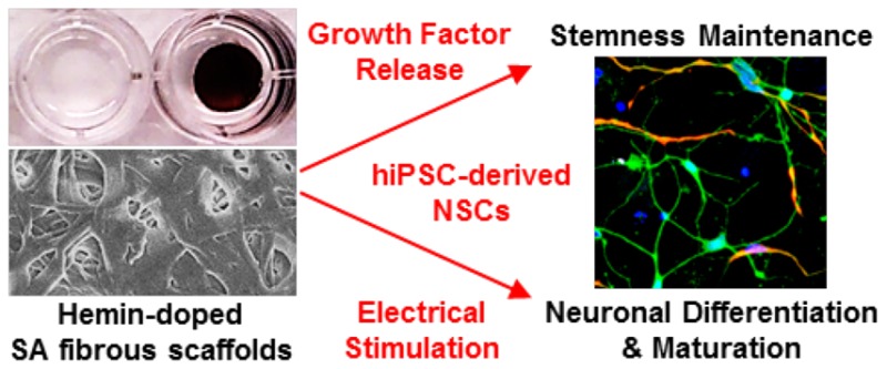
Neural tissue engineering (TE) represents a promising new avenue of therapy to support nerve recovery and regeneration. To recreate the complex environment in which neurons develop and mature, the ideal biomaterials for neural TE require a number of properties and capabilities including the appropriate biochemical and physical cues to adsorb and release specific growth factors. Here, we present neural TE constructs based on electrospun serum albumin (SA) fibrous scaffolds. We doped our SA scaffolds with an iron-containing porphyrin, hemin, to confer conductivity, and then functionalized them with different recombinant proteins and growth factors to ensure cell attachment and proliferation. We demonstrated the potential for these constructs combining topographical, biochemical, and electrical stimuli by testing them with clinically relevant neural populations derived from human induced pluripotent stem cells (hiPSCs). Our scaffolds could support the attachment, proliferation, and neuronal differentiation of hiPSC-derived neural stem cells (NSCs), and were also able to incorporate active growth factors and release them over time, which modified the behavior of cultured cells and substituted the need for growth factor supplementation by media change. Electrical stimulation on the doped SA scaffold positively influenced the maturation of neuronal populations, with neurons exhibiting more branched neurites compared to controls. Through promotion of cell proliferation, differentiation, and neurite branching of hiPSC-derived NSCs, these conductive SA fibrous scaffolds are of broad application in nerve regeneration strategies.
Keywords: neural tissue engineering, neural stem cells, electrospinning, electrical stimulation, hemin, serum albumin
1. Introduction
Nerve injuries in either the central nervous system (CNS) or peripheral nervous system (PNS) can cause severe neurological deficits, resulting in the diminished physical and psychological well-being of patients.1,2 As the regenerative ability of the human nervous system is limited, these injuries can be permanent due also to the relative shortage of therapeutic options.2 Although nerve repair in the PNS can be achieved by autologous transfer of a normal nerve from an uninjured site, its application is restricted by limited tissue supply and the potential undesirable effects at the donor site.3 Given these considerations, tissue engineering strategies incorporating both biomaterials and cellular therapies represent a promising new avenue for therapeutic nerve repair and neuroregeneration.
In order to successfully recreate intricate and functional neural tissue in vitro, several different components and properties are necessary. First, building a bioengineered construct that mimics neural tissue requires the presence of a scaffold that can provide housing for a supportive extracellular environment along with the physical guidance necessary for nerve repair and neural regeneration.4,5 A widely used method to construct scaffolds for neural tissue engineering (TE) is electrospinning: this is a simple, potentially large-scale fabrication process capable of generating nano/microscale fibers for 3D scaffold architecture.6,7 While artificial polymeric scaffolds are widely used, the generation and use of self-derived biomaterials from adults remains to be explored.8 Serum albumin (SA), which is abundant and can be rapidly replenished in humans or animals, has been widely used in biomedical research for cell culture and storage, in vitro fertilization, and transplantation.9 As a natural carrier protein with multiple ligand binding sites and the ability to bind different cellular receptors, SA has also been exploited as a potential delivery platform for drugs and biomolecules.10 With its ease of isolation from clinical samples and lowest cost compared to other commercially available proteins, SA has become an attractive autogenic biomaterial for TE with optimal cell compatibility.8,11,12
In addition to a suitable scaffold supporting cellular growth and differentiation, it is also desirable to integrate multiple different cues into any tissue-engineered construct to recapitulate the tissue’s natural microenvironment. A variety of different factors have already been used in tissue engineering scaffolds to promote nerve regeneration. For example, nerve growth factor (NGF),13 brain-derived neurotrophic factor (BDNF),14,15 and glial-derived neurotrophic factor (GDNF)16 successfully encapsulated into different electrospun scaffolds showed that the synergistic effects of nanofiber topography and sustained growth factor delivery could promote cellular proliferation and differentiation in targeted cells. As a well-characterized neurogenic factor affecting neural stem cell (NSC) proliferation and differentiation, fibroblast growth factor-2 (FGF2) (basic FGF)17 has also been encapsulated into fibrous biomaterials for TE purposes.13,18
An ideal construct for neural TE also needs to take into account the inherent electroresponsive properties of neurons and the effect of electrical stimulation on developing neuronal networks. Several studies have suggested an important role of external electrical stimulation on enhancing neuronal differentiation, neurite sprouting, neurite outgrowth, and neurite orientation.19−22 In recent years, fibrous scaffolds with electrically conductive properties have been used in neural TE to actively modulate cell responses like differentiation and neurite guidance following application of external electric stimuli.23 For example, various conducting polymers, such as polypyrrole (PPy)24,25 and polyaniline (PANI),26,27 graphene,28 and gold nanoparticles,29 have individually been blended with other polymers and successfully electrospun into fibrous materials. Other studies also achieved conductive fibrous scaffolds by depositing a layer of conducting polymers or metallic nanoparticles onto the template fibers.30−34
In this study, we sought to combine these complex stimuli—topography, growth factor release, and electrical stimulation—into a single construct designed specifically for neural TE applications. The scaffold construct is based on our recent study of a new type of conductive freestanding hybrid material based on the bovine SA protein.35 After electrospinning, we doped the SA mat with a hemin dopant, which resulted in a very high macroscopic conductance. Hemin, the oxidized form of iron protoporphyrin IX (Fe3+), is critical to cellular homeostasis and gene regulation, and is also one of the main electron mediators in nature.36 This facile approach using electrospinning and doping in hemin solution eliminates the need for a complicated fabrication process. The large affinity of hemin to the SA mat also avoids the leaching of dopants out of the mat in an aqueous environment.35 The 3D electrospun fibrous structure, the biocompatibility of the raw materials, and the strength of electrical conductivity make hemin-doped SA mats a promising material for bioelectronic devices and tissue engineered constructs.
To test the potential application of the SA constructs for neural TE, we utilized human induced pluripotent stem cell (hiPSC)-derived NSCs, which represent an attractive cell source for TE and regenerative medicine.37 These cells are generated by reprogramming somatic cells such as fibroblasts into an undifferentiated state.38 The generated cells are capable of self-renewal, providing a stable source of pluripotent cells; unlike embryonic stem cells (ESCs), hiPSCs can bypass certain ethical issues and can also be used for the production of patient-specific cells, reducing the risk of immune rejection.37 While many studies done within the field of neural TE often use immortalized cell lines such as SH-SY5Y and PC12 cells, or primary cultures from animal models,32,39,40 the hiPSC-derived neural populations provide a more clinically and biologically relevant platform by which to test the function of designed biomaterials. We demonstrated the potential of this protein-based material that can be readily produced from an autologous origin, as a source for growth factor signaling by incorporating a human recombinant protein, FGF2, into the SA fibrous scaffolds. Finally, the conductive nature of the construct enabled us to explore the effect of electrical stimulation on clinically relevant human NSCs. The feasibility of using the hemin-doped SA fibrous scaffold for neural TE is concluded with the functional enhancement of neuronal cell behaviors.
2. Materials and Methods
2.1. Fabrication of Electrospun SA Fibrous Scaffolds
SA scaffolds were fabricated as previously described by Amdursky et al.35 Briefly, bovine SA lyophilized powder, ≥96% (agarose gel electrophoresis), (Sigma-Aldrich, U.K.) was dissolved in a 90 v/v % 2,2,2-trifluoroethanol (Sigma-Aldrich) solution. We premixed the polymer solution (14 w/v % bovine SA) on a tube roller overnight, and 5 v/v % of 2-mercaptoethanol (Sigma-Aldrich) was added 30 min before electrospinning. The polymer solution was electrospun using a syringe equipped with an 18 gauge steel needle, a 10 kV potential, a throw distance of 10 cm, and a syringe flow rate of 0.8 mL/h. Electrospun SA mats were obtained on an Al-foil-wrapped rotating drum with 10 cm diameter at an average speed of approximately 1000 rpm at a relative humidity (RH) of 35–55%.
2.2. Preparation of Hemin-Doped SA Fibrous Scaffolds
The hemin dopant (porcine; Sigma-Aldrich) was first dissolved in dimethyl sulfoxide (DMSO; Sigma-Aldrich) to make an 11 mM stock hemin solution. We then made the final doping solution of 130 μM hemin by diluting the stock solution with phosphate buffer solution (PBS). Electrospun SA mats were cut into smaller samples (10 mm wide, 30 mm long) and doped in the solution with shaking at room temperature overnight. Prior to use, the doped SA samples were immersed in PBS at least overnight to wash away the residual unincorporated dopants.
2.3. Electrochemical Properties of Hemin-Doped SA Fibrous Scaffolds
Nondoped and hemin-doped SA fibrous scaffolds were immersed in PBS in the cell culture constructs (described in section 2.6). Cyclic voltammetry (CV) was performed using an eDAQ 410 System (eDAQ Pty Ltd., Australia) by applying cyclic potential in the ±0.75 V bias range at a scan rate of 40 mV/s.
2.4. Scanning Electron Microscopy (SEM)
SA mats were dehydrated by incubation for at least 30 min in progressively higher concentrations of ethanol (Sigma-Aldrich) in water (30, 50, 70, 80, 90, and 100 v/v %) under gentle shaking. SA mats were then incubated in 100 v/v % EtOH for 1 h, with refreshing of the solution three times, followed by one wash in hexamethyldisilazane (Sigma-Aldrich) for 5 min, and finally air drying overnight under a chemical hood. A 10 nm thin film of Cr was deposited on the sample by sputter coating to prevent charging. The sample was analyzed at 5 keV with a Sigma 300 SEM instrument (ZEISS, Germany).
2.5. Cell Culture
The human episomal iPSC line (Epi-hiPSC) (Thermo Fisher Scientific, U.K.) was maintained on Matrigel-coated culture plates in feeder-free culture conditions with the use of chemically defined Essential 8 media (Thermo Fisher Scientific). Colonies of Epi-hiPSCs were passaged by dissociation with 0.5 M EDTA (pH 8.0; Thermo Fisher Scientific) diluted 1:1000 in sterile PBS when they reached 80–90% confluence. Neural differentiation was based on a published protocol with some modifications.41 Briefly, Epi-hiPSC cultures were used for neural conversion when they reached confluence. The cells were differentiated into neuroectoderm by dual-SMAD signaling inhibition42 using neural induction medium [Advanced DMEM/F-12 medium (Thermo Fisher Scientific), 1 v/v % N-2 supplement (Invitrogen, U.K.), 0.2 v/v % B27 Supplement (Invitrogen), 1 v/v % penicillin/streptomycin (Invitrogen), 1 v/v % GlutaMAX (Invitrogen) supplemented with SB431542 (10 μM; Tocris, U.K.), dorsomorphin (2 μM; Calbiochem, U.K.), and N-acetylcysteine (1 mM; Sigma-Aldrich)] for 6–7 d. After enzymatic dissociation, we then passaged and plated down the neural stem cells (NSCs) on laminin-coated plates in NSCR base medium [Advanced DMEM/F-12 medium (Thermo Fisher Scientific), 1 v/v % N-2 supplement (Invitrogen), 0.2 v/v % B27 Supplement (Invitrogen), 1 v/v % penicillin/streptomycin (Invitrogen), 1 v/v % GlutaMAX (Invitrogen)]. After 3–5 d culture, Epi-hiPSC-derived NSCs proliferated and formed neural rosette structures. The NSCs were then maintained in F20 medium [NSCR base medium supplemented with 20 ng/mL FGF2 (PeproTech)]. NSCs were usually subcultured every 5–7 d on laminin-coated plates for the first few passages and on Matrigel-coated culture plates for later passages.
2.6. Design of Cell Culture Device
We assembled the electrical stimulation device for Epi-hiPSC-derived NSCs on glass slides and hemin-doped fibrous scaffolds based on a conventional six-well tissue culture plate (Figure S1A). Each scaffold was placed on a glass coverslip in a well. Two Au mylar (Vaculayer, Canada) electrodes were placed on top of the two ends of the scaffold with the conductive side (10 mm × 10 mm) facing down and the rest of the electrodes tightly folded alongside the culture well. An ∼50 mm thick poly(dimethylsiloxane) (PDMS, Dow Corning, U.K.) ring fitted to the well with 10 mm inner diameter was placed and pressed on the stack of cover glass, SA fibrous scaffold, and mylar electrodes. The seam between the scaffold and the mylar electrodes was sealed by pressing the PDMS ring tightly to the attached cover glass. The culture devices of electrical stimulation were sterilized by one wash with 70 v/v % ethanol, three washes of sterile PBS, and exposure to UV light for an hour.
2.7. Laminin Coating of Hemin-Doped SA Fibrous Scaffolds
The scaffolds were assembled into a well device as described in section 2.6 without placing Au mylar electrodes. The mats were incubated overnight in 500 μL of 0.1 mg/mL poly-d-lysine (PDL; Sigma-Aldrich) solution, followed by three washes with PBS and then 500 μL of 10 μg/mL laminin (Sigma-Aldrich) overnight. The coating of laminin was evaluated with the amount of the remaining laminin in the coating solution after incorporation. Samples were analyzed using a Mouse Laminin ELISA Kit (Abcam, U.K.) according to manufacturer instructions. Absorbance values from ELISA plates were measured at 450 nm with a multimode microplate reader (SpectraMax M5; Molecular Devices, USA) and were normalized to the glass control.
For the time-lapse laminin adsorption assay, 20 PDL-coated and 20 PDL-laminin-coated nondoped, hemin-doped, and glass substrates were prepared as mentioned above. Four PDL-coated and 4 PDL-laminin-coated substrates were stained at different time points (day 0, day 2, week 1, week 2, and week 3), as described in section 2.12. The time-lapse laminin adsorption was determined by subtracting the background mean fluorescence intensity of PDL-coated substrates from the mean fluorescence intensity of the PDL-laminin-coated substrates to eliminate the effect of autofluorescence of SA and the fluorescence quenching caused by the hemin dopant (10 fields were analyzed per batch of sample, and a total of 40 fields were analyzed). The stability of the laminin coating was evaluated by comparing the background-subtracted mean fluorescence intensity at different time points to day 0 within the substrate.
2.8. Incorporation and Release of FGF2 of Hemin-Doped SA Fibrous Scaffolds
The scaffolds were assembled into a well device as described in section 2.6 without placing Au mylar electrodes. For the incorporation assay, the device was incubated overnight in 500 μL of 0.1 mg/mL PDL (Sigma-Aldrich) solution followed by three washes with PBS and then 500 μL of 10 μg/mL laminin (Sigma-Aldrich) with 0.1 μg/mL FGF2 (PeproTech, U.K.) overnight. The incorporation of FGF2 was evaluated by the amount of the remaining FGF2 in the coating solution after incorporation (day 0). The release of FGF2 was examined by replacing the previous solution into fresh PBS at day 0 and day 2 and collecting the solution at day 2 and day 5, respectively. The time points were chosen in accordance with the frequency of the media exchange. FGF2 was examined by measuring the FGF2 released in the collected solution. Samples were analyzed using an FGF2 Human ELISA Kit (Thermo Fisher Scientific) according to manufacturer instructions with five different batches of scaffolds analyzed. Absorbance values from ELISA plates were measured at 450 nm with a multimode microplate reader (SpectraMax M5; Molecular Devices) and were normalized to the initial FGF2 solution.
2.9. Viability and Neuronal Differentiation of hiPSC-Derived NSCs on Hemin-Doped SA Fibrous Scaffolds
Before cells were seeded, the cell culture device was assembled and precoated with PDL and laminin, as described in section 2.7. hiPSC-Derived NSCs were seeded at a concentration of 200 000 cells in 300 μL of NSCR base medium in the inner well of the PDMS ring (d = 10 mm). After 30 min of cell adhesion, the constructs were topped up with an extra 3 mL of medium, and cultured at 37 °C in a humid, 5% CO2 incubator. After 24 h, the viability of NSCs on the scaffolds was evaluated using a LIVE/DEAD Viability/Cytotoxicity Kit for mammalian cells (Thermo Fisher Scientific), which determines cell viability based on the membrane integrity of cells. Viable cells were stained with green fluorescence through the reaction of calcein AM with intracellular esterase, while dead cells were stained with red fluorescence, indicating lost or damaged cell membranes. To test if the scaffolds were biocompatible for neuronal differentiation of hiPSC-derived NSCs, the cells were seeded at a concentration of 200 000 cells in NSCR neuron medium [NSCR base medium supplemented with 10 ng/mL BDNF (R&D Systems) and 10 ng/mL GDNF (R&D Systems)] for 7 d, with medium exchanged every 2–3 d. The cells were fixed after 7 d of neuronal differentiation and stained for cell observation.
2.10. hiPSC-Derived NSCs on FGF2-Incorporated Hemin-Doped SA Fibrous Scaffolds and for Electrical Stimulation Studies
The cell culture constructs were assembled as described in section 2.6 and then prepared with or without 0.1 μg/mL FGF2 (PeproTech) incorporation, as described in section 2.8. NSCR base medium was used for electrical stimulation group and blank controls for FGF2 incorporation experiments, while F20 medium was used for positive controls for FGF2 incorporation experiments. Confluent Epi-hiPSC-derived NSCs were dissociated with Accutase (Sigma-Aldrich) and seeded on SA fibrous scaffolds in the inner well of the PDMS ring (d = 10 mm) with 62 500 cells in 300 μL of medium. After 30 min of cell adhesion, the constructs were topped up with an extra 3 mL of medium, and cultured at 37 °C in a humid, 5% CO2 incubator.
2.11. Electrical Stimulation of hiPSC-Derived NSCs on Hemin-Doped SA Fibrous Scaffolds
Previous studies have shown that the effects of electrical stimulation on cell behavior vary depending on parameters such as electrical stimuli, cell types, material interfaces, and experimental setups.32,43−45 In our experiment, after 48 h of cell seeding for cell attachment and spreading, trains of 50 ms electrical pulses of 50 mV/cm at 2 Hz for a period of 2 h were applied at day 2 and day 3 with a 24 h interval between each stimulus via a 33500 Series Trueform waveform generator (Agilent, USA). The constructs were replaced with fresh media immediately after the electrical stimulation to avoid undesirable effects of electrical stimulation on the media. After the final stimulation, Epi-hiPSC-derived NSCs were further cultured on the scaffolds for 48 h and then fixed and stained for cell observation. The schematic of the experimental scheme and the stimulation parameters are shown in Figure S1B.
2.12. Immunostaining, Fluorescence Microscopy, and Confocal Fluorescence Microscopy
For laminin immunofluorescent staining, SA fibrous scaffolds were blocked with 3 v/v % goat serum (Sigma-Aldrich) for 30 min, followed with primary antibody, laminin (1:1000; Abcam) for 1 h, and secondary antibodies (Alexa Fluor dyes; Thermo Fisher Scientific) for 30 min. For cell culture experiments, cells with scaffolds were fixed in 4 v/v % paraformaldehyde (Sigma-Aldrich) for 20 min, permeabilized with 0.2 v/v % Triton X-100 (Sigma-Aldrich) for 15 min, and blocked with 3 v/v % goat serum for 45 min. Cells were then incubated for 1.5 h with primary antibodies, nestin (1:500; Millipore, U.K.), βIII-tubulin (1:1000; Sigma-Aldrich), and Ki67 (1:1000; Abcam), followed with DAPI (Sigma-Aldrich) and secondary antibodies for 45 min. The stained samples were mounted on slides with FluorSave Reagent (Millipore) and stored at 4 °C. Images of laminin immunofluorescent staining were acquired with an epifluorescent microscope (EVOS FL Cell Imaging System; Life Technologies, U.K.), whereas images of the cell experiments were acquired with a SP5MP/FLIM inverted confocal microscope (Leica, Germany) by sequential scanning. The thickness of the acquired sample sections was about 40 μm, and z stacks of typically 20 2 μm slices were imaged.
2.13. Imaging Analysis and Statistical Analysis
Image analysis was performed with ImageJ 64 (version 2). To quantify fiber diameter, measurements were made from 300 fibers taken randomly in the SEM images. The cell viability on the scaffolds was evaluated by the total coverage area of live cells (green) and the number of dead cells (red) after 24 h of cell seeding, where a total of 35 images in each group were analyzed. NSC proliferation and differentiation for biocompatibility were analyzed on five different batches of scaffolds with cell coverage using βIII-tubulin, a neuron-specific marker, and nestin, a neural stem cell marker. NSC proliferation, differentiation, and neurite branching were analyzed with the proliferation marker, Ki67, and βIII-tubulin, using the “Cell Counter” plugin. Cell proliferation and differentiation were evaluated with the percentage of the Ki67+ cells and ßIII-tubulin+ cells over the total number of cells within a field of 40×, respectively. Neurite outgrowth was evaluated using the “Neurite Tracings” plugin. For statistical analysis, all experiments were conducted three times (with two biological replicates and three technical replicates in each experiment). One-way ANOVA with post hoc Tukey’s test was used throughout the study unless specified otherwise. A p-value <0.05 was considered statistically significant and all results represent means ± s.e.m. (In the diagrams, * represents p < 0.05, ** represents p ≤ 0.01, and *** represents p ≤ 0.001.)
3. Results
3.1. Morphology and Characterization of Hemin-Doped SA Fibrous Scaffolds
We fabricated SA scaffolds as previously described by Amdursky et al.35 using an electrospinning process (Figure 1A) and examined the morphology and topography of the SA mats with SEM imaging (Figure 1). The electrospinning of the SA solution produced fibrous mats (∼110 μm thick) with an average fiber diameter of 0.95 ± 0.13 μm (Figure 1B, panel 1). Doping the SA mats with hemin resulted in a comparatively rough surface compared to the smooth and uniform surface of the nondoped SA mats (Figure 1C); however, there was no significant difference in the average fiber diameters (1.04 ± 0.08 μm) (Figure 1B, panel 3). To enhance cell attachment and promote neuronal differentiation, we further coated a layer of PDL and laminin using physical adsorption. After coating, the hemin-doped mats (Figure 1B, panel 4) exhibited an increase in their fiber diameters (1.71 ± 0.23 μm) that were significantly larger than the nondoped SA mats coated with PDL and laminin (Figure 1B, panel 2; 0.68 ± 0.06 μm). Both of the laminin-coated SA mats exhibited some aggregates resulting from the adsorption of the laminin proteins.
Figure 1.

Hemin-doped SA fibrous scaffolds. (A) Schematic of SA fibrous scaffold sample preparation and photographs of nondoped SA fibrous scaffolds (white, left) and hemin-doped SA fibrous scaffolds (black, right). (B) SEM image of (1) nondoped SA fibrous scaffolds, (2) nondoped SA fibrous scaffolds with laminin coating, (3) hemin-doped SA fibrous scaffolds, and (4) hemin-doped SA fibrous scaffolds with laminin coating. (C) SEM imaging for surface roughness of the nondoped SA mats (left) and the hemin-doped SA mats (right). (D) Fiber diameter of nondoped and hemin-doped SA fibrous scaffolds with and without laminin coating. (One-way ANOVA with post hoc Tukey’s test was used. The results represent means ± s.e.m. * represents p < 0.05 and ** represents p ≤ 0.01 compared to hemin-doped SA + LN.)
We next sought to investigate the ability of the scaffolds to adsorb and retain a laminin coating, in order to assess the biofunctionalization. We first coated the scaffold for 24 h in a laminin containing solution with a known concentration, and then collected the coating solution and evaluated the laminin adsorption using ELISA to determine the amount of remaining laminin in the coating solution after incorporation (Figure 2A). The results showed a significantly higher amount of remaining laminin in the nondoped SA scaffolds, indicating the hemin-doped SA scaffolds and the PDL-coated glass slides exhibited more laminin adsorption compared to the nondoped SA scaffolds. While initial laminin adsorption is critical for cell attachment, the maintenance of the adsorbed laminin during the culture period can further support cell adhesion, proliferation, and differentiation. To understand if different substrates exhibited different capabilities for laminin maintenance, we coated the laminin on the nondoped, hemin-doped SA scaffolds and the PDL-coated glass slides, and examined the immunofluorescent staining of the laminin coating at different time points (Figure 2B). The results showed a significant decrease in fluorescence intensity of the laminin protein on both the nondoped SA scaffolds and glass controls after 3 weeks of being immersed in cell culture medium, with medium exchange every 2–3 days. However, the hemin-doped SA scaffolds were able to maintain the laminin coating over the time period tested.
Figure 2.

Laminin adsorption on the SA scaffolds. (A) Remaining laminin in the coating solution measured by ELISA. (One-way ANOVA with post hoc Tukey’s test was used. The results represent means ± s.e.m. ** represents p ≤ 0.01.) (B) Time-lapse laminin adsorption to glass slides, nondoped, and hemin-doped SA fibrous scaffolds. (One-way ANOVA with post hoc Tukey’s test was used to compare the results of the same substrate at different time points. The results represent means ± s.e.m. * represents p < 0.05 compared to D0 nondoped SA; # represents p < 0.05 compared to D0 glass.)
3.2. Cell Viability, Proliferation, and Neuronal Differentiation on Hemin-Doped SA Fibrous Scaffolds
To test the potential of our hemin-doped SA mats for neural TE applications, we cultured hiPSC-derived NSCs on our constructs, and investigated stem cell proliferation and induction of neuronal differentiation. We seeded the hiPSC-derived NSCs on the mats in the assembled cell constructs (Figure 3A) and examined the cell viability with the LIVE/DEAD Viability assay 24 h after cell seeding (Figure 3B). The staining showed no significant differences in the percentage of live cell coverage between the nondoped SA, hemin-doped SA mats, and glass control (Figure 3C, top panel; nondoped SA: 9.50 ± 5.69%; hemin-doped SA: 23.56 ± 8.43%; glass control: 31.63 ± 9.35%). However, there was less live cell coverage and significantly more dead cells per analyzed image on the nondoped SA mats compared to the hemin-doped SA mats (Figure 3C, bottom panel; nondoped SA: 2385 ± 419; hemin-doped SA: 1194 ± 311; glass control: 1330 ± 201), indicating that the hemin dopant does not cause significant adverse effects on cell biocompatibility and improves cell attachment and the viability of hiPSC-derived NSCs compared to the nondoped SA mats.
Figure 3.

Effect of the SA scaffolds on cell behaviors. (A) Schematic of cell culture on SA fibrous scaffolds. (B) LIVE/DEAD fluorescent images on glass slides, nondoped, and hemin-doped SA fibrous scaffolds (calcein AM, green, live cell; ethidium homodimer-1, red, dead cell). (C) Cell viability evaluated as the percentage of live cell coverage and the number of dead cells per analyzed field on glass slides, nondoped, and hemin-doped SA fibrous scaffolds. (D) hiPSC-derived NSCs stained with βIII-tubulin, a neuronal marker, and nestin, a neural stem cell marker, after 7 days of neuronal differentiation (βIII-tubulin, green; nestin, red). (E) Total cell coverage after 7 days of neuronal differentiation on nondoped, hemin-doped SA scaffolds, and the glass slides. (F) Percentage of βIII-tubulin+ cell and nestin+ cell coverage over the total cell coverage on different substrates. (One-way ANOVA with post hoc Tukey’s test was used. The results represent means ± s.e.m. * represents p < 0.05.)
To examine the effect of the nondoped and hemin-doped SA fibrous scaffolds on the proliferation and differentiation of hiPSC-derived NSCs, we stained the cells with βIII-tubulin, a neuronal marker, and nestin, a neural stem cell marker, after 7 days of differentiation (Figure 3D). The immunostaining revealed that hiPSC-derived NSCs on the nondoped SA scaffolds clumped together and formed sphere-like structures, while the cells on the hemin-doped SA scaffolds and the glass control were widely spread on the substrates. The total cell coverage on the nondoped SA scaffolds (13.81 ± 4.05%) was significantly lower than the hemin-doped SA scaffolds (30.90 ± 3.18%) and glass control (32.09 ± 4.30%) (Figure 3E). We further examined the percentage of cells expressing βIII-tubulin and nestin over the total cell coverage. While there were many immature neurons coexpressing both βIII-tubulin and nestin markers at day 7, there was no significant difference in the percentage of βIII-tubulin+ cells and nestin+ cells over the total cell coverage between the substrates (Figure 3F). Overall, even though the cellular coverage of the nondoped mats was lower compared to other groups, the SA scaffolds were biocompatible to the cell system and did not hinder cell proliferation and neuronal differentiation of the hiPSC-derived NSCs.
3.3. Effect of Growth Factor Release with Hemin-Doped SA Fibrous Scaffolds
Next, we evaluated the ability of our SA scaffolds to incorporate and release signaling factors. We chose to work with FGF2 as an example of recombinant protein with a clear effect on NSC populations. For incorporation of FGF2, we took advantage of the ability of SA to noncovalently bind a variety of small molecules and peptides, similarly to the hemin doping procedure. We placed the SA scaffold into an FGF2 solution and, using ELISA as a measure of the quantity of recombinant protein bound to our material, evaluated the amount of remaining FGF2 in the coating solution following overnight incubation (Figure 4). We observed a significant binding of FGF2 to the SA scaffold, while 94.80 ± 2.27% and 99.57 ± 0.12% of the initial FGF2 in the solution went inside the nondoped and hemin-doped SA scaffolds, respectively (Figure 4A). After ensuring that FGF2 could be incorporated into our scaffolds, we further examined its release by measuring the FGF2 in solution after 2 and 5 days using ELISA (Figure 4B). Our results indicated that the incorporation of FGF2 into the SA scaffolds induced a slow release profile (days time scale). We found that the release of FGF2 from the nondoped SA scaffolds was 0.12 ± 0.05% and 0.18 ± 0.02% of the initial FGF2 in the solution (corresponding to a release of 0.13% and 0.19%, respectively, of the initial loaded FGF2 in the nondoped SA scaffold) for days 2 and 5, respectively. From the hemin-doped SA scaffolds, the release of FGF2 was 0.34 ± 0.12% and 0.65 ± 0.50% of the initial FGF2 in the solution (corresponding to a release of 0.34% and 0.65%, respectively, of the initial loaded FGF2 in the hemin-doped SA scaffold) for days 2 and 5, respectively.
Figure 4.

Incorporation and release of FGF2 from the SA scaffolds. (A) The remaining amount of FGF2 after incorporation is measured by ELISA. (One-way ANOVA with post hoc Tukey’s test was used. The results represent means ± s.e.m. *** represents p ≤ 0.001.) (B) Release profile for the amount of FGF2 released in the solution using ELISA for nondoped and hemin-doped SA fibrous scaffolds at day 2 and day 5. (A two-sample t test was used to compare hemin-doped SA and nondoped SA at day 2 and day 5, respectively. The results represent means ± s.e.m.)
Following the successful incorporation of FGF2 into our scaffolds, we examined the cellular responses of our hiPSC-derived NSCs for proliferation and neurogenesis by focusing on the effects of FGF2 incorporated nondoped and hemin-doped SA mats on the cells (Figure 5A). We found that the FGF2-incorporated nondoped SA mats were sufficient to maintain a proliferative (Ki67+) cell population of 33.75 ± 2.52% over 5 days of being cultured in basal medium, similar to the degree of regular exchange of FGF2-containing medium with nonincorporated nondoped SA mats (31.48 ± 3.79%). The mats supplied with soluble FGF2, FGF2-incoporated mats, and the combination of both had a significantly higher proliferative cell population compared to the control nondoped mats without FGF2 (17.86 ± 3.22%). For hemin-doped SA mats, the results also demonstrated a higher percentage of proliferative cells with soluble FGF2, FGF2-incorporated mats, and the combination of both compared to the control hemin-doped mats without significance (Figure 5B and Table S1).
Figure 5.

Effects of the SA scaffolds on cell behavior. (A) Confocal fluorescence images of hiPSC-derived NSCs on nondoped and hemin-doped SA scaffolds with or without FGF2 incorporation (FGF2Mats or X) in basal medium and FGF2-containing medium (FGF2Medium), respectively (nestin, red; βIII-tubulin, green; DAPI, blue). (B) Cell proliferation as assessed with the percentage of the Ki67+ cells. (One-way ANOVA with post hoc Tukey’s test was used. The results represent means ± s.e.m. * represents p < 0.05; ** represents p ≤ 0.01; # represents p ≤ 0.001 compared to nondoped SA [X + FGF2Medium], [FGF2Mats + basal medium], and [FGF2Mats + FGF2Medium]; & represents p < 0.05 compared to nondoped SA [FGF2Mats + basal medium] and p ≤ 0.01 compared to [FGF2Mats + FGF2Medium]; @ represents p < 0.05 compared to nondoped [FGF2Mats + FGF2Medium]; $ represents p ≤ 0.01 compared to nondoped SA [X + FGF2Medium] and [FGF2Mats + basal medium] and p ≤ 0.001 compared to [FGF2Mats + FGF2Medium].) (C) Neuronal differentiation as assessed with the percentage of βIII-tubulin+ cells. (One-way ANOVA with post hoc Tukey’s test was used. The results represent means ± s.e.m. * represents p < 0.05; ** represents p ≤ 0.01.)
We examined neuronal differentiation of the hiPSC-derived NSCs by measuring the percentage of βIII-tubulin+ cells. On both nondoped and hemin-doped SA mats, the NSCs in the control group without any FGF2 exhibited higher neuronal differentiation compared to other groups with FGF2 (Figure 5C). This result was consistent with the predicted effect of FGF2 in maintaining the proliferating stem state of the NSCs. These results also demonstrated that the hemin-doped SA mats overall had a higher percentage of differentiated cells compared to the nondoped SA mats, which hinted at a preference toward neuronal differentiation on the hemin-doped mats. The highest neuronal differentiation occurred on the hemin-doped SA mats without soluble FGF2 and FGF2 incorporation (38.88 ± 7.34%) compared to the other groups (Table S2).
3.4. Effect of Electrical Stimulation on Hemin-Doped SA Fibrous Scaffolds
The conductive properties of hemin-doped SA mats (∼2 mS/cm) have been detailed previously by us in Amdursky et al.35 To use the hemin-doped SA scaffolds for in vitro electrical stimulation in our current study, we developed the cell culture construct and optimized the stimulation protocol. The electrical characterization (current–voltage behavior) of the scaffolds assembled in our constructs showed that, when a voltage was applied, a higher current passed through the hemin-doped SA scaffolds compared to the nondoped SA scaffolds and PBS control (Figure S2 and text within). Due to the cells exhibiting different attachment patterns on the nondoped and hemin-doped SA mats, we chose glass slides as the nonconductive control in our electrical stimulation experiments, since this would decouple the effect of electrical stimulation through the conductive material and the effect of material properties on the cells.
We first examined the effects of electrical stimulation on cell proliferation and differentiation (Figure 6A). Our results showed that there were significantly more Ki67+ cells on the glass control (38.57 ± 5.25%) compared to the hemin-doped SA scaffolds with and without electrical stimulation (11.05 ± 3.04% and 15.10 ± 4.08%, respectively). Although the number of Ki67+ cells decreased following the application of electrical stimulation to the glass control (23.90 ± 6.06%; p = 0.149), the cell percentage remained similar on the hemin-doped SA mats with and without electrical stimulation (Figure 6B). For neuronal differentiation (Figure 6C), the glass slides with electrical stimulation (28.27 ± 4.26%) exhibited higher neuronal differentiation compared to the unstimulated control (p = 0.309), which suggested the effectiveness of the applied stimuli. Both hemin-doped SA scaffolds with and without electrical stimulation exhibited enhanced neuronal differentiation with a significantly higher percentage of βIII-tubulin+ cells (40.73 ± 7.64% and 38.91 ± 5.63%) compared to the glass control (14.93 ± 2.51%).
Figure 6.

Effects of electrical stimulation on glass slides and hemin-doped SA fibrous scaffolds. (A) Confocal fluorescence images of hiPSC-derived NSCs on glass slides and doped SA scaffolds with and without electrical stimulation, respectively (nestin, red; DAPI, blue; left panels: βIII-tubulin, green; right panels: Ki67, yellow). (B) Cell proliferation analyzed as the percentage of Ki67+ cells. (C) Neuronal differentiation analyzed as the percentage of βIII-tubulin+ cells. (One-way ANOVA with post hoc Tukey’s test was used. The results represent means ± s.e.m. * represents p < 0.05; ** represents p ≤ 0.01.)
To examine the effects of electrical stimulation on neuronal maturation and network formation as applied through the hemin-doped SA scaffolds, we examined neurite outgrowth and branching in the hiPSC-derived neurons (Figure 7). With electrical stimulation, we observed a nonsignificant increase in neurite outgrowth on both the glass slides and hemin-doped SA scaffolds compared to the unstimulated groups (Table S3). However, the neurons exhibited the longest neurite outgrowth on the stimulated hemin-doped SA scaffolds (78.14 ± 6.40 μm) among all groups examined. The cells on the hemin-doped SA mats with stimulation also demonstrated significantly more neurite branching compared to all other groups (3.76 ± 0.12 branches). The amount of neurite branching of cells was as follows: on the unstimulated hemin-doped SA mats, 2.92 ± 0.15; on the glass slides with electrical stimulation, 2.60 ± 0.30; and on the glass slides without electrical stimulation, 2.43 ± 0.17.
Figure 7.

Effects of electrical stimulation on glass slides and hemin-doped SA fibrous scaffolds. (A) Neurite outgrowth after electrical stimulation on glass slides (left) and hemin-doped SA scaffolds (right) (nestin, red; DAPI, blue; βIII-tubulin, green). (B) Average neurite length with and without electrical stimulation. (C) Neurite branching with and without electrical stimulation. (One-way ANOVA with post hoc Tukey’s test was used. The results represent means ± s.e.m. * represents p < 0.05; ** represents p ≤ 0.01; *** represents p ≤ 0.001.)
4. Discussion
The restoration of functional nerve tissue after injury is an intricate process requiring multiple stimuli from the microenvironment.5 Here, we present the first report of a hemin-doped SA scaffold in neural TE, and demonstrate its ability to synergistically provide topographical, biochemical, and electrical stimuli to actively enhance cellular responses.
Our initial characterization of the biointerface with SEM imaging revealed that, while the nondoped and hemin-doped SA scaffolds exhibited a similar fiber diameter, the fiber diameter increased significantly on the hemin-doped scaffolds compared to the nondoped SA scaffolds after coating with PDL-laminin. This also correlated with the presence of putative protein aggregates and a general increase of surface roughness along the fibers. We also observed significantly more laminin adsorption on the hemin-doped SA mats compared to the nondoped SA mats, and a more stable laminin coating on the hemin-doped SA mats. Together, these results would suggest that the difference of the morphology and diameter between the nondoped and hemin-doped mats after laminin coating could possibly be related to the difference in their ability to adsorb extracellular matrix protein such as laminin. The hemin dopant could be a key regulator in this process, where the electrostatic interactions between hemin and SA affect substrate-dependent differences in peptide and protein adsorption, which offers additional TE advantages. Previously, to improve cell–material interaction, studies have shown that an increased surface roughness in an optimum range and a large surface area can increase cell attachment and cell–material integration advancing bioelectronic interfaces.46,47 In addition, extracellular matrix proteins can also dynamically regulate cell behaviors, with laminin being especially shown to guide and promote neuronal differentiation and neurite outgrowth.48 By examining cell viability, proliferation, and differentiation, we found that, on the nondoped SA mats, hiPSC-derived NSCs tended to group in clusters. By contrast, on the hemin-doped SA mats, the cells exhibited better cell attachment and performance across the whole mat. In summary, the properties of the laminin-coated hemin-doped SA scaffolds could provide surface roughness, high surface area, interconnected porosity, and higher protein adsorption propensity, as well as the ability to support cellular attachment, growth, and differentiation. Together, these findings demonstrate the potential use of our scaffolds as an attractive biomaterial for neural interfaces.
Since the addition of bioactive factors into TE constructs has been known to improve cell–tissue interactions, we further examined the potential of our hemin-doped SA scaffolds for bioactive molecule release. Previous studies have successfully delivered bioactive factors, such as growth factors and neurotrophic factors, through TE substrates via physical incorporation, chemical conjugation, and polymeric microsphere delivery.49−51 Numerous studies have demonstrated the incorporation of nerve growth factor into 2D conductive substrates, and recently also into 3D conductive scaffolds.23,52−55 For example, Lee et al. fabricated PPy-coated electrospun poly(lactic acid-co-glycolic acid) (PLGA) nanofibers and chemically immobilized NGF onto their surface.56 Zeng et al. also synthesized conductive NGF-conjugated PPy-poly(l-lactic acid) (PLLA) fibers through oxidation polymerization and EDC chemistry.57 Because the stability and functionality of growth factors is critical but difficult to maintain during chemical incorporation,51 our SA system—with its innate property as a natural transport protein—could be an advantageous platform for delivering biomolecule stimuli. In the study, we showed that our SA-based hybrid system was able to physically incorporate the model growth factor FGF2, and eliminate relatively complex chemical reactions and polymeric microsphere preparation. Our results also showed a functional outcome of increased proliferative cells on the FGF2-incorporated SA scaffolds compared to nonincorporated mats, and demonstrated for the first time that an electrospun SA scaffold could be used for the incorporation and release of bioactive molecules. It was also interesting to find a trend of higher incorporation and higher release of FGF2 in the hemin-doped SA scaffolds similarly to what was observed with the laminin incorporation. Although the specific means by which hemin regulates protein incorporation remains unclear, we speculate it could be due to a combination of the following: (1) the electrostatic effects of hemin to the SA substrate, (2) hemin’s effects on SA’s FGF2 binding sites, and (3) the effects of the increased laminin adsorption on both electrostatic incorporation and the binding affinity of FGF2. This would suggest that hemin-doping of the SA scaffold, besides conferring electroactive properties to the constructs, can also enhance its bioactive applications.
In our study, we also tested the potential of our hemin-doped SA scaffolds for in vitro electrical stimulation application. Previously, Schmidt et al. reported that extracellular electrical fields of 100 mV for 2 h applied with an oxidized PPy film on PC12 cells could increase neurite outgrowth.58 Recent studies also reported that, with electrical stimuli of 100 mV/cm for 2 h, PC12 cells on PPy-coated PLGA nanofibers and NGF-conjugated PLLA fibers showed increases in neurite outgrowth and extension compared to the unstimulated controls.32,57 In our study, we decided to work with even lower electrical fields of 50 mV/cm at trains of 50 ms, 2 Hz electrical pulses, since this electric stimulation protocol did not adversely affect cell viability in our system and could potentially recapitulate the endogenous bursting of human pluripotent stem cell-derived neurons.59 It is generally recommended to work with the lowest electric fields possible to avoid undesirable electrical phenomena next to the electrode, such as water splitting or the reduction/oxidation of ions.43 We found that increasing the electric field to 100 mV/cm resulted in unwanted cell death (data not shown), which might have been related to the tolerance of our human clinically relevant cells to high electric fields. Following electrical stimulation, our glass control exhibited an increase in neuronal differentiation compared to the unstimulated glass control, in line with previous studies which showed that electrical stimulation increased neuronal differentiation in human stem cells.60−62 The effects of electrical stimulation are known to vary according to cell type, substrate condition, and the exerted intensity.32,43−45 In particular, comparing the effect of electrical stimulation on the differentiation potential between immortalized cell lines and iPSC-derived neural progenitors has proven especially difficult, since iPSC-derived cultures are inherently more sensitive to change in culture conditions. However, in our experiments, the overall viability of our cells and a trend to increased neuronal differentiation after electrical stimulation suggested that our applied stimuli are biocompatible and sufficient to modulate cellular behavior. On the other hand, cells on the hemin-doped SA scaffolds exhibited a significantly higher neuronal differentiation, and there was no significant difference between the unstimulated and electrically stimulated groups. This observation could have been the result of the intrinsic properties of the hemin-doped SA scaffolds inducing NSC differentiation under basal conditions; the electrical stimulation could thereby not exert any additive effects, since the population was uniformly differentiated. Hemin has previously been reported to have neurotrophic effects that promote survival and induce neurite outgrowth in both neuroblastoma cell lines and neurons derived from neural crests.63,64 Other studies have shown that hemin is potentially neurotoxic via various oxidative and nonoxidative mechanisms.65,66 The precise biochemical mechanism by which the hemin acts in the SA scaffold to preferentially give neuronal differentiation will require further elucidation in future studies.
Beyond its effects on neuronal differentiation, electrical stimulation on the conductive SA constructs proved to be a very effective means by which to modulate neuronal maturation responses. Indeed, we observed significant morphological changes of the hiPSC-derived neurons, and especially when it came to neurite branching. Previous studies reported that electrical stimulation enhances neurite outgrowth and neurite branching in human neuroblastoma cell lines and animal cells.41,53,58,67 While the effects of electrical stimulation have been widely studied, the mechanisms are not yet fully understood.19,22 Some important mechanisms have been proposed for the mediation of electric signals including (1) membrane proteins, which undergo conformational change and induce integrin-dependent signaling; (2) the modulation of voltage-sensitive Ca2+ channels and voltage-sensitive small-molecule transporters (i.e., serotonin) inducing ion and small molecule influx, and further triggering downstream signaling; (3) voltage-sensitive phosphatase activity, which affects phosphoinositide-sensitive signaling; (4) changes in the cytoplasmic content of H+, K+, and other ions; (5) electrical stimulation reorganization of membrane receptor distribution, which affects actin filaments and microtubules and further amplifies the gradient of intracellular Ca2+; and (6) electrophoresis of morphogens through the cytoplasm.20,22,68 It has also been shown that electrical stimulation induces gradients of ions and molecules within tissue fluid, culture medium, and cell culture substrates, and affects both protein adsorption and the macroscopic protein structure in the extracellular environment.58,67,69,70 Our use of a conductive scaffold added an additional dimension of complexity, since it introduced an electronic/ionic current within the scaffold itself in addition to the ionic current in the solution.35 Using a very low electric field in our study allowed us to try and pinpoint the effect of electrical stimulation on the scaffold by avoiding additional effects on electrophoresis and conformational changes of proteins, along with the redox effects in the cell culture media and extracellular environment. As shown above, the main difference found for the hiPSC-derived neurons on the hemin-doped SA scaffolds (with or without electrical stimulation) was in the neuronal structures associated with maturation, such as neurite branching. We propose that the electrical stimuli applied through the hemin-doped fibrous mats simulate physiological neuronal activity and subsequently induce large neurite branching.
5. Conclusion
In this study, we present a neural TE platform based on the hemin-doped SA scaffold. This scaffold can actively provide a supportive microenvironment and present topographical guidance, bioactive molecule incorporation, and electrical stimulation to promote cell engraftment, proliferation, and differentiation. Our scaffold is biocompatible and supports the culture and differentiation of clinically relevant iPSC-derived populations, and is capable of incorporating and releasing growth factors to modulate cell behavior over long periods of time. With optimized electrical stimulation parameters, we have also successfully achieved structural maturation with enhanced neurite branching. Our hemin-doped SA-based constructs represent a valuable new platform by which to satisfy the major essential needs in neural TE with clinical application, namely, the combination of autogenic cells with a feasible artificial fabricated autogenic tissue engineered construct.
Acknowledgments
C.-C.H. was supported by a Top University Strategic Alliance PhD scholarship from Taiwan. A.S. was funded by the grant from the UK Regenerative Medicine Platform “A Hub for Engineering and Exploiting the Stem Cell Niche” (MR/K026666/1). M.M.S. acknowledges the grant “State of the Art Biomaterials Development and Characterization of the Cell-Biomaterial Interface” (MR/L012677/1) from the MRC. N.A. was supported by Marie Curie actions FP7 through the Intra-European Marie Curie Fellowship “ConPilus” (623123). C.B. was supported by Defence Science and Technology Laboratory (Salisbury, U.K.) for his PhD research. M.M.S. acknowledges support from the Wellcome Trust Senior Investigator Grant (098411/Z/12/Z) and the ERC Consolidator grant “Naturale CG” (616417). The authors acknowledge use of the characterization facilities within the Harvey Flower Electron Microscopy Suite (Department of Materials) and the Facility for Imaging by Light Microscopy (FILM) at Imperial College London.
Supporting Information Available
The Supporting Information is available free of charge on the ACS Publications website at DOI: 10.1021/acsami.7b18179.
Further experimental details and results, including the schematic of the electrical stimulation setup and waveform in Figure S1, conductivity measurements of the SA-based scaffolds in Figure S2, and more detailed results for cell proliferation, neuronal differentiation, and neurite outgrowth in Tables S1–S3 (PDF)
Author Present Address
∥ A.S.: Division of Tissue Engineering & Biophotonics, King’s College London, London SE1 9RT, U.K.
Author Present Address
⊥ N.A.: Schulich Faculty of Chemistry, Technion - Israel Institute of Technology, Haifa, 3200003, Israel.
The authors declare no competing financial interest.
Notes
Raw data is available on request from rdm-enquiries@imperial.ac.uk.
Supplementary Material
References
- Evans G. R. D. Challenges to Nerve Regeneration. Semin Surg Oncol 2000, 19, 312–318. . [DOI] [PubMed] [Google Scholar]
- He J.; Wang X.-M.; Spector M.; Cui F.-Z. Scaffolds for Central Nervous System Tissue Engineering. Front. Mater. Sci. 2012, 6, 1–25. 10.1007/s11706-012-0157-5. [DOI] [Google Scholar]
- Ray W. Z.; Mackinnon S. E. Management of Nerve Gaps: Autografts, Allografts, Nerve Transfers, and End-to-Side Neurorrhaphy. Exp. Neurol. 2010, 223, 77–85. 10.1016/j.expneurol.2009.03.031. [DOI] [PMC free article] [PubMed] [Google Scholar]
- Shokrgozar M. A.; Mottaghitalab F.; Mottaghitalab V.; Farokhi M. Fabrication of Porous Chitosan/Poly(Vinyl Alcohol) Reinforced Single-Walled Carbon Nanotube Nanocomposites for Neural Tissue Engineering. J. Biomed. Nanotechnol. 2011, 7, 276–284. 10.1166/jbn.2011.1284. [DOI] [PubMed] [Google Scholar]
- Schmidt C. E.; Leach J. B. Neural Tissue Engineering: Strategies for Repair and Regeneration. Annu. Rev. Biomed. Eng. 2003, 5, 293–347. 10.1146/annurev.bioeng.5.011303.120731. [DOI] [PubMed] [Google Scholar]
- Tamayol A.; Akbari M.; Annabi N.; Paul A.; Khademhosseini A.; Juncker D. Fiber-Based Tissue Engineering: Progress, Challenges, and Opportunities. Biotechnol. Adv. 2013, 31, 669–687. 10.1016/j.biotechadv.2012.11.007. [DOI] [PMC free article] [PubMed] [Google Scholar]
- Datta S.; Rameshbabu A. P.; Bankoti K.; Maity P. P.; Das D.; Pal S.; Roy S.; Sen R.; Dhara S. Oleoyl-Chitosan-Based Nanofiber Mats Impregnated with Amniotic Membrane Derived Stem Cells for Accelerated Full-Thickness Excisional Wound Healing. ACS Biomater. Sci. Eng. 2017, 3, 1738–1749. 10.1021/acsbiomaterials.7b00189. [DOI] [PubMed] [Google Scholar]
- Li P.-S.; Liang Lee I.; Yu W.-L.; Sun J.-S.; Jane W.-N.; Shen H.-H. A Novel Albumin-Based Tissue Scaffold for Autogenic Tissue Engineering Applications. Sci. Rep. 2015, 4, 5600. 10.1038/srep05600. [DOI] [PMC free article] [PubMed] [Google Scholar]
- Horváthy D. B.; Simon M.; Schwarz C. M.; Masteling M.; Vácz G.; Hornyák I.; Lacza Z. Serum Albumin as a Local Therapeutic Agent in Cell Therapy and Tissue Engineering. BioFactors 2017, 43, 315–330. 10.1002/biof.1337. [DOI] [PubMed] [Google Scholar]
- Larsen M. T.; Kuhlmann M.; Hvam M. L.; Howard K. A. Albumin-Based Drug Delivery: Harnessing Nature to Cure Disease. Mol. Cell. Ther. 2016, 4, 3. 10.1186/s40591-016-0048-8. [DOI] [PMC free article] [PubMed] [Google Scholar]
- Fleischer S.; Shapira A.; Regev O.; Nseir N.; Zussman E.; Dvir T. Albumin Fiber Scaffolds for Engineering Functional Cardiac Tissues. Biotechnol. Bioeng. 2014, 111, 1246–1257. 10.1002/bit.25185. [DOI] [PubMed] [Google Scholar]
- Ferrero-Gutierrez A.; Menendez-Menendez Y.; Alvarez-Viejo M.; Meana A.; Otero J. New Serum-Derived Albumin Scaffold Seeded with Adipose-Derived Stem Cells and Olfactory Ensheathing Cells Used to Treat Spinal Cord Injured Rats. Histol. Histopathol. 2013, 28, 89–100. [DOI] [PubMed] [Google Scholar]
- Dinis T. M.; Vidal G.; Jose R. R.; Vigneron P.; Bresson D.; Fitzpatrick V.; Marin F.; Kaplan D. L.; Egles C. Complementary Effects of Two Growth Factors in Multifunctionalized Silk Nanofibers for Nerve Reconstruction. PLoS One 2014, 9, e109770. 10.1371/journal.pone.0109770. [DOI] [PMC free article] [PubMed] [Google Scholar]
- Low W. C.; Rujitanaroj P.-O.; Wang F.; Wang J.; Chew S. Y. Nanofiber-Mediated Release of Retinoic Acid and Brain-Derived Neurotrophic Factor for Enhanced Neuronal Differentiation of Neural Progenitor Cells. Drug Delivery Transl. Res. 2015, 5, 89–100. 10.1007/s13346-013-0131-5. [DOI] [PubMed] [Google Scholar]
- Zhou K.; Thouas G.; Bernard C.; Forsythe J. S. 3d Presentation of a Neurotrophic Factor for the Regulation of Neural Progenitor Cells. Nanomedicine (London, U. K.) 2014, 9, 1239–1251. 10.2217/nnm.13.112. [DOI] [PubMed] [Google Scholar]
- Wang T.-Y.; Bruggeman K. A. F.; Sheean R. K.; Turner B. J.; Nisbet D. R.; Parish C. L. Characterization of the Stability and Bio-Functionality of Tethered Proteins on Bioengineered Scaffolds: Implications for Stem Cell Biology and Tissue Repair. J. Biol. Chem. 2014, 289, 15044–15051. 10.1074/jbc.M113.537381. [DOI] [PMC free article] [PubMed] [Google Scholar]
- Woodbury M. E.; Ikezu T. Fibroblast Growth Factor-2 Signaling in Neurogenesis and Neurodegeneration. J. Neuroimmune Pharmacol. 2014, 9, 92–101. 10.1007/s11481-013-9501-5. [DOI] [PMC free article] [PubMed] [Google Scholar]
- Santos T. C.; Morton T. J.; Moritz M.; Pfeifer S.; Reise K.; Marques A. P.; Castro A. G.; Reis R. L.; van Griensven M. Vascular Endothelial Growth Factor and Fibroblast Growth Factor-2 Incorporation in Starch-Based Bone Tissue-Engineered Constructs Promote the in Vivo Expression of Neovascularization Mediators. Tissue Eng., Part A 2013, 19, 834–848. 10.1089/ten.tea.2010.0741. [DOI] [PubMed] [Google Scholar]
- Rajabi A. H.; Jaffe M.; Arinzeh T. L. Piezoelectric Materials for Tissue Regeneration: A Review. Acta Biomater. 2015, 24, 12–23. 10.1016/j.actbio.2015.07.010. [DOI] [PubMed] [Google Scholar]
- McCaig C. D.; Song B.; Rajnicek A. M. Electrical Dimensions in Cell Science. J. Cell Sci. 2009, 122, 4267–4276. 10.1242/jcs.023564. [DOI] [PubMed] [Google Scholar]
- McCaig C. D.; Rajnicek A. M. Electrical Fields, Nerve Growth and Nerve Regeneration. Exp. Physiol. 1991, 76, 473–494. 10.1113/expphysiol.1991.sp003514. [DOI] [PubMed] [Google Scholar]
- Balint R.; Cassidy N. J.; Cartmell S. H. Electrical Stimulation: A Novel Tool for Tissue Engineering. Tissue Eng., Part B 2012, 19, 48–57. 10.1089/ten.teb.2012.0183. [DOI] [PubMed] [Google Scholar]
- Lee J. Y. Electrically Conducting Polymer-Based Nanofibrous Scaffolds for Tissue Engineering Applications. Polym. Rev. 2013, 53, 443–459. 10.1080/15583724.2013.806544. [DOI] [Google Scholar]
- Kai D.; Prabhakaran M. P.; Jin G.; Ramakrishna S. Polypyrrole-Contained Electrospun Conductive Nanofibrous Membranes for Cardiac Tissue Engineering. J. Biomed. Mater. Res., Part A 2011, 99A, 376–385. 10.1002/jbm.a.33200. [DOI] [PubMed] [Google Scholar]
- Liu X.; Chen J.; Gilmore K. J.; Higgins M. J.; Liu Y.; Wallace G. G. Guidance of Neurite Outgrowth on Aligned Electrospun Polypyrrole/Poly(Styrene-Β-Isobutylene-Β-Styrene) Fiber Platforms. J. Biomed. Mater. Res., Part A 2010, 94A, 1004–1011. 10.1002/jbm.a.32675. [DOI] [PubMed] [Google Scholar]
- Li M.; Guo Y.; Wei Y.; MacDiarmid A. G.; Lelkes P. I. Electrospinning Polyaniline-Contained Gelatin Nanofibers for Tissue Engineering Applications. Biomaterials 2006, 27, 2705–2715. 10.1016/j.biomaterials.2005.11.037. [DOI] [PubMed] [Google Scholar]
- Ghasemi-Mobarakeh L.; Prabhakaran M. P.; Morshed M.; Nasr-Esfahani M. H.; Ramakrishna S. Electrical Stimulation of Nerve Cells Using Conductive Nanofibrous Scaffolds for Nerve Tissue Engineering. Tissue Eng., Part A 2009, 15, 3605–3619. 10.1089/ten.tea.2008.0689. [DOI] [PubMed] [Google Scholar]
- Yang Y.; Ding X.; Zou T.; Peng G.; Liu H.; Fan Y. Preparation and Characterization of Electrospun Graphene/Silk Fibroin Conductive Fibrous Scaffolds. RSC Adv. 2017, 7, 7954–7963. 10.1039/C6RA26807B. [DOI] [Google Scholar]
- Ravichandran R.; Sridhar R.; Venugopal J. R.; Sundarrajan S.; Mukherjee S.; Ramakrishna S. Gold Nanoparticle Loaded Hybrid Nanofibers for Cardiogenic Differentiation of Stem Cells for Infarcted Myocardium Regeneration. Macromol. Biosci. 2014, 14, 515–525. 10.1002/mabi.201300407. [DOI] [PubMed] [Google Scholar]
- Aznar-Cervantes S.; Roca M. I.; Martinez J. G.; Meseguer-Olmo L.; Cenis J. L.; Moraleda J. M.; Otero T. F. Fabrication of Conductive Electrospun Silk Fibroin Scaffolds by Coating with Polypyrrole for Biomedical Applications. Bioelectrochemistry 2012, 85, 36–43. 10.1016/j.bioelechem.2011.11.008. [DOI] [PubMed] [Google Scholar]
- Hong K. H.; Oh K. W.; Kang T. J. Preparation of Conducting Nylon-6 Electrospun Fiber Webs by the in Situ Polymerization of Polyaniline. J. Appl. Polym. Sci. 2005, 96, 983–991. 10.1002/app.21002. [DOI] [Google Scholar]
- Lee J. Y.; Bashur C. A.; Goldstein A. S.; Schmidt C. E. Polypyrrole-Coated Electrospun Plga Nanofibers for Neural Tissue Applications. Biomaterials 2009, 30, 4325–4335. 10.1016/j.biomaterials.2009.04.042. [DOI] [PMC free article] [PubMed] [Google Scholar]
- Singh A.; Hede S.; Sastry M. Spider Silk as an Active Scaffold in the Assembly of Gold Nanoparticles and Application of the Gold–Silk Bioconjugate in Vapor Sensing. Small 2007, 3, 466–473. 10.1002/smll.200600413. [DOI] [PubMed] [Google Scholar]
- Xie J.; MacEwan M. R.; Willerth S. M.; Li X.; Moran D. W.; Sakiyama-Elbert S. E.; Xia Y. Conductive Core-Sheath Nanofibers and Their Potential Application in Neural Tissue Engineering. Adv. Funct. Mater. 2009, 19, 2312–2318. 10.1002/adfm.200801904. [DOI] [PMC free article] [PubMed] [Google Scholar]
- Amdursky N.; Wang X.; Meredith P.; Riley D. J.; Payne D. J.; Bradley D. D. C.; Stevens M. M. Electron Hopping across Hemin-Doped Serum Albumin Mats on Centimeter-Length Scales. Adv. Mater. 2017, 29, 1700810. 10.1002/adma.201700810. [DOI] [PMC free article] [PubMed] [Google Scholar]
- Tsiftsoglou A. S.; Tsamadou A. I.; Papadopoulou L. C. Heme as Key Regulator of Major Mammalian Cellular Functions: Molecular, Cellular, and Pharmacological Aspects. Pharmacol. Ther. 2006, 111, 327–345. 10.1016/j.pharmthera.2005.10.017. [DOI] [PubMed] [Google Scholar]
- Willerth S. M. Neural Tissue Engineering Using Embryonic and Induced Pluripotent Stem Cells. Stem Cell Res. Ther. 2011, 2, 17. 10.1186/scrt58. [DOI] [PMC free article] [PubMed] [Google Scholar]
- Takahashi K.; Tanabe K.; Ohnuki M.; Narita M.; Ichisaka T.; Tomoda K.; Yamanaka S. Induction of Pluripotent Stem Cells from Adult Human Fibroblasts by Defined Factors. Cell 2007, 131, 861–872. 10.1016/j.cell.2007.11.019. [DOI] [PubMed] [Google Scholar]
- Corey J. M.; Lin D. Y.; Mycek K. B.; Chen Q.; Samuel S.; Feldman E. L.; Martin D. C. Aligned Electrospun Nanofibers Specify the Direction of Dorsal Root Ganglia Neurite Growth. J. Biomed. Mater. Res., Part A 2007, 83A, 636–645. 10.1002/jbm.a.31285. [DOI] [PubMed] [Google Scholar]
- Bolin M. H.; Svennersten K.; Wang X.; Chronakis I. S.; Richter-Dahlfors A.; Jager E. W. H.; Berggren M. Nano-Fiber Scaffold Electrodes Based on Pedot for Cell Stimulation. Sens. Actuators, B 2009, 142, 451–456. 10.1016/j.snb.2009.04.062. [DOI] [Google Scholar]
- Chang Y.-J.; Hsu C.-M.; Lin C.-H.; Lu M. S.-C.; Chen L. Electrical Stimulation Promotes Nerve Growth Factor-Induced Neurite Outgrowth and Signaling. Biochim. Biophys. Acta, Gen. Subj. 2013, 1830, 4130–4136. 10.1016/j.bbagen.2013.04.007. [DOI] [PubMed] [Google Scholar]
- Chambers S. M.; Fasano C. A.; Papapetrou E. P.; Tomishima M.; Sadelain M.; Studer L. Highly Efficient Neural Conversion of Human Es and Ips Cells by Dual Inhibition of Smad Signaling. Nat. Biotechnol. 2009, 27, 275–280. 10.1038/nbt.1529. [DOI] [PMC free article] [PubMed] [Google Scholar]
- Cogan S. F. Neural Stimulation and Recording Electrodes. Annu. Rev. Biomed. Eng. 2008, 10, 275–309. 10.1146/annurev.bioeng.10.061807.160518. [DOI] [PubMed] [Google Scholar]
- Patel N.; Poo M.-M. Orientation of Neurite Growth by Extracellular Electric Fields. J. Neurosci. 1982, 2, 483–496. [DOI] [PMC free article] [PubMed] [Google Scholar]
- Zou Y.; Qin J.; Huang Z.; Yin G.; Pu X.; He D. Fabrication of Aligned Conducting Ppy-Plla Fiber Films and Their Electrically Controlled Guidance and Orientation for Neurites. ACS Appl. Mater. Interfaces 2016, 8, 12576–12582. 10.1021/acsami.6b00957. [DOI] [PubMed] [Google Scholar]
- Ateh D. D.; Navsaria H. A.; Vadgama P. Polypyrrole-Based Conducting Polymers and Interactions with Biological Tissues. J. R. Soc., Interface 2006, 3, 741–752. 10.1098/rsif.2006.0141. [DOI] [PMC free article] [PubMed] [Google Scholar]
- Khan S. P.; Auner G. G.; Newaz G. M. Influence of Nanoscale Surface Roughness on Neural Cell Attachment on Silicon. Nanomedicine 2005, 1, 125–129. 10.1016/j.nano.2005.03.007. [DOI] [PubMed] [Google Scholar]
- Luckenbill-Edds L. Laminin and the Mechanism of Neuronal Outgrowth. Brain Res. Rev. 1997, 23, 1–27. 10.1016/S0165-0173(96)00013-6. [DOI] [PubMed] [Google Scholar]
- Chen C.; Kong X.; Lee I.-S. Modification of Surface/Neuron Interfaces for Neural Cell-Type Specific Responses: A Review. Biomed. Mater. 2016, 11, 014108. 10.1088/1748-6041/11/1/014108. [DOI] [PubMed] [Google Scholar]
- Lee A. C.; Yu V. M.; Lowe J. B. III; Brenner M. J.; Hunter D. A.; Mackinnon S. E.; Sakiyama-Elbert S. E. Controlled Release of Nerve Growth Factor Enhances Sciatic Nerve Regeneration. Exp. Neurol. 2003, 184, 295–303. 10.1016/S0014-4886(03)00258-9. [DOI] [PubMed] [Google Scholar]
- Pfister L. A.; Papaloïzos M.; Merkle H. P.; Gander B. Nerve Conduits and Growth Factor Delivery in Peripheral Nerve Repair. J. Peripher. Nerv. Syst. 2007, 12, 65–82. 10.1111/j.1529-8027.2007.00125.x. [DOI] [PubMed] [Google Scholar]
- George P. M.; LaVan D. A.; Burdick J. A.; Chen C.-Y.; Liang E.; Langer R. Electrically Controlled Drug Delivery from Biotin-Doped Conductive Polypyrrole. Adv. Mater. 2006, 18, 577–581. 10.1002/adma.200501242. [DOI] [Google Scholar]
- Gomez N.; Schmidt C. E. Nerve Growth Factor-Immobilized Polypyrrole: Bioactive Electrically Conducting Polymer for Enhanced Neurite Extension. J. Biomed. Mater. Res., Part A 2007, 81A, 135–149. 10.1002/jbm.a.31047. [DOI] [PMC free article] [PubMed] [Google Scholar]
- Kim D.-H.; Richardson-Burns S. M.; Hendricks J. L.; Sequera C.; Martin D. C. Effect of Immobilized Nerve Growth Factor on Conductive Polymers: Electrical Properties and Cellular Response. Adv. Funct. Mater. 2007, 17, 79–86. 10.1002/adfm.200500594. [DOI] [Google Scholar]
- Evans A. J.; Thompson B. C.; Wallace G. G.; Millard R.; O’Leary S. J.; Clark G. M.; Shepherd R. K.; Richardson R. T. Promoting Neurite Outgrowth from Spiral Ganglion Neuron Explants Using Polypyrrole/Bdnf-Coated Electrodes. J. Biomed. Mater. Res., Part A 2009, 91A, 241–250. 10.1002/jbm.a.32228. [DOI] [PubMed] [Google Scholar]
- Lee J. Y.; Bashur C. A.; Milroy C. A.; Forciniti L.; Goldstein A. S.; Schmidt C. E. Nerve Growth Factor-Immobilized Electrically Conducting Fibrous Scaffolds for Potential Use in Neural Engineering Applications. IEEE Trans. Nanobiosci. 2012, 11, 15–21. 10.1109/TNB.2011.2159621. [DOI] [PMC free article] [PubMed] [Google Scholar]
- Zeng J.; Huang Z.; Yin G.; Qin J.; Chen X.; Gu J. Fabrication of Conductive Ngf-Conjugated Polypyrrole–Poly(L-Lactic Acid) Fibers and Their Effect on Neurite Outgrowth. Colloids Surf., B 2013, 110, 450–457. 10.1016/j.colsurfb.2013.05.012. [DOI] [PubMed] [Google Scholar]
- Schmidt C. E.; Shastri V. R.; Vacanti J. P.; Langer R. Stimulation of Neurite Outgrowth Using an Electrically Conducting Polymer. Proc. Natl. Acad. Sci. U. S. A. 1997, 94, 8948–8953. 10.1073/pnas.94.17.8948. [DOI] [PMC free article] [PubMed] [Google Scholar]
- Weick J. P.; Liu Y.; Zhang S.-C. Human Embryonic Stem Cell-Derived Neurons Adopt and Regulate the Activity of an Established Neural Network. Proc. Natl. Acad. Sci. U. S. A. 2011, 108, 20189–20194. 10.1073/pnas.1108487108. [DOI] [PMC free article] [PubMed] [Google Scholar]
- Yamada M.; Tanemura K.; Okada S.; Iwanami A.; Nakamura M.; Mizuno H.; Ozawa M.; Ohyama-Goto R.; Kitamura N.; Kawano M.; Tan-Takeuchi K.; Ohtsuka C.; Miyawaki A.; Takashima A.; Ogawa M.; Toyama Y.; Okano H.; Kondo T. Electrical Stimulation Modulates Fate Determination of Differentiating Embryonic Stem Cells. Stem Cells 2007, 25, 562–570. 10.1634/stemcells.2006-0011. [DOI] [PubMed] [Google Scholar]
- Huang Y.-J.; Wu H.-C.; Tai N.-H.; Wang T.-W. Carbon Nanotube Rope with Electrical Stimulation Promotes the Differentiation and Maturity of Neural Stem Cells. Small 2012, 8, 2869–2877. 10.1002/smll.201200715. [DOI] [PubMed] [Google Scholar]
- Park S. J.; Park J. S.; Yang H. N.; Yi S. W.; Kim C.-H.; Park K.-H. Neurogenesis Is Induced by Electrical Stimulation of Human Mesenchymal Stem Cells Co-Cultured with Mature Neuronal Cells. Macromol. Biosci. 2015, 15, 1586–1594. 10.1002/mabi.201500115. [DOI] [PubMed] [Google Scholar]
- Ishii D. N.; Maniatis G. M. Haemin Promotes Rapid Neurite Outgrowth in Cultured Mouse Neuroblastoma Cells. Nature 1978, 274, 372–374. 10.1038/274372a0. [DOI] [PubMed] [Google Scholar]
- Zhu Y.; Sun Y.; Jin K.; Greenberg D. A. Hemin Induces Neuroglobin Expression in Neural Cells. Blood 2002, 100, 2494–2498. 10.1182/blood-2002-01-0280. [DOI] [PubMed] [Google Scholar]
- Goldstein L.; Teng Z.-P.; Zeserson E.; Patel M.; Regan R. F. Hemin Induces an Iron-Dependent, Oxidative Injury to Human Neuron-Like Cells. J. Neurosci. Res. 2003, 73, 113–121. 10.1002/jnr.10633. [DOI] [PubMed] [Google Scholar]
- Robinson S. R.; Dang T. N.; Dringen R.; Bishop G. M. Hemin Toxicity: A Preventable Source of Brain Damage Following Hemorrhagic Stroke. Redox Rep. 2009, 14, 228–235. 10.1179/135100009X12525712409931. [DOI] [PubMed] [Google Scholar]
- Kotwal A.; Schmidt C. E. Electrical Stimulation Alters Protein Adsorption and Nerve Cell Interactions with Electrically Conducting Biomaterials. Biomaterials 2001, 22, 1055–1064. 10.1016/S0142-9612(00)00344-6. [DOI] [PubMed] [Google Scholar]
- Levin M. Large-Scale Biophysics: Ion Flows and Regeneration. Trends Cell Biol. 2007, 17, 261–270. 10.1016/j.tcb.2007.04.007. [DOI] [PubMed] [Google Scholar]
- Nguyen H. T.; Wei C.; Chow J. K.; Nguy L.; Nguyen H. K.; Schmidt C. E. Electric Field Stimulation through a Substrate Influences Schwann Cell and Extracellular Matrix Structure. J. Neural Eng. 2013, 10, 046011. 10.1088/1741-2560/10/4/046011. [DOI] [PubMed] [Google Scholar]
- Forciniti L.; Ybarra J. III; Zaman M. H.; Schmidt C. E. Schwann Cell Response on Polypyrrole Substrates Upon Electrical Stimulation. Acta Biomater. 2014, 10, 2423–2433. 10.1016/j.actbio.2014.01.030. [DOI] [PubMed] [Google Scholar]
Associated Data
This section collects any data citations, data availability statements, or supplementary materials included in this article.