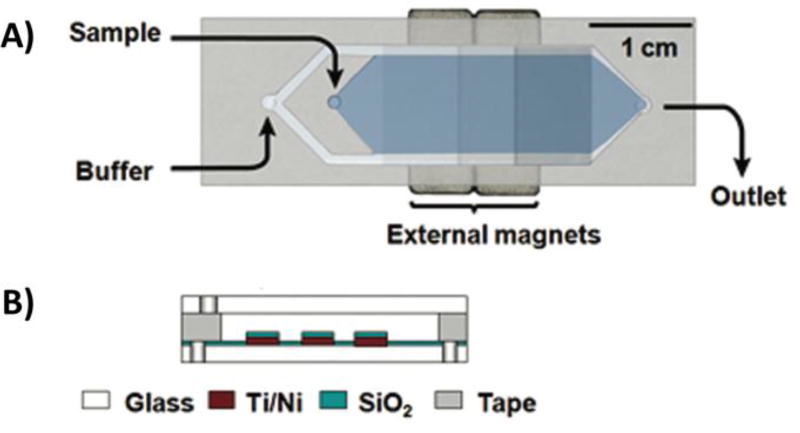
Figure 5.
Schematic of the MMS device. A) Top view and B) side view. Sequential buffer and sample inlets flow sample towards the outlet. The patterned Ti/Ni grids become magnetized by external rare-earth magnets and traps magnetic beads containing bound oligos. Adapted from Qian et al74 with permission from the American Chemical Society.

