

Abstract
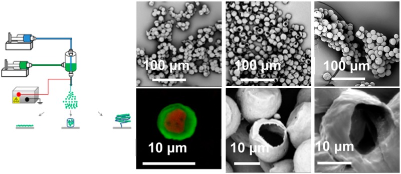
We describe the co-electrospraying of hollow microspheres from a polycaprolactone (PCL) shell solution and various core solutions including water, cyclohexane, poly(ethylene oxide) (PEO), and polyethylene glycol (PEG), using different collectors. The morphologies of the resultant microspheres were characterized by scanning electron microscopy (SEM), confocal microscopy, and nano-X-ray computed tomography (nano-XCT). The core/shell solution miscibility played an important role in the co-electrospraying process and the formation of microsphere structures. Spherical particles were more likely to be produced from miscible combinations of core/shell solutions than from immiscible ones. Hollow PCL microspheres with a single hole in their surfaces were produced when an ethanol bath was used as the collector. The mechanism by which the core/shell structure is transformed into single-hole hollow microspheres is proposed to be primarily based on the evaporation through the shell and extraction by ethanol of the core solution and is described in detail. Additionally, we present a 3D macroscopic tubular structure composed of hollow PCL microspheres, directly assembled on a copper wire collector during co-electrospraying. SEM and nano-XCT confirm that microspheres in the 3D bulk structure remain hollow.
Introduciton
Electrospraying and its variant, electrospinning, are two techniques capable of fabricating nano- or microsized droplets/fibers from polymer solutions by means of electric forces.1,2 These two techniques are convertible by tuning the polymer molecular weight3 and/or polymer solution concentration.4 Co-electrospraying and co-electrospinning are modified versions of electrospraying and electrospinning for the fabrication of core–shell or hollow polymeric micro/nanosized spheres/fibers,5,6 which are also convertible by controlling the core/shell solution properties.7
Solid polycaprolactone (PCL) nano/microspheres can be prepared by the technique of electrospraying for applications in drug and growth factor delivery.8−12 Recently, red blood cell-mimicking nonspherical particles were produced by the electrospraying of poly(lactic-co-glycolic acid) (PLGA) and cellulose derivatives, which can find application in areas of drug delivery, medical imaging, and the establishment of improved disease models.13,14 Hollow PCL microspheres have lower density and larger surface area than solid microspheres and may also have a wide range of potential applications in the controlled local delivery of drugs and proteins. Despite the extensive recent efforts to prepare hollow polymer nano/microspheres,15 there have been very limited studies on PCL hollow microspheres.16 Co-electrospraying has mainly been used to prepare core–shell spheres for nano/microencapsulation.17−21 No previous study has been conducted on the production of hollow PCL microspheres by co-electrospraying.
In electrospraying/co-electrospraying, nano/microspheres are usually collected on the surface of aluminum foil11 or a water bath,8,22 resulting in the formation of a 2D planar layer of microspheres. However, in the context of biomimetic microstructures, 2D electrosprayed/co-electrosprayed constructs of microspheres lack the microenvironment characteristics of 3D tissues. Despite the popularity of nano/microspheres created by electrospraying/co-electrospraying, the production of microsphere constructs in a 3D bulk form remains a challenge. Hollow PCL microfibers have been recently produced in one-step by co-electrospinning of the appropriate solution pairs, i.e., PCL solution as shell and PEO solution as core23 or PCL as shell and sugar as core.24 Recently, electrospinning has been demonstrated to prepare 3D tubular nanofibrous structures for use as nerve and vascular scaffolds.25,26
Given the above background, it is of interest to investigate whether the scenarios of producing hollow PCL microfibers and 3D nanofibers can be extended to co-electrospraying of hollow PCL microspheres and 3D microsphere constructs, respectively. Unlike previously reported methods that require several chemical agents and complex processes,16 co-electrospraying would be a one-step process for hollow sphere generation without using extra surfactants or large quantities of solvents.
Here we report the production of hollow microspheres with/without a single surface hole by the one-step co-electrospraying of PCL in chloroform as shell and polyethylene glycol (PEG) in chloroform as core. A 3D tubular structure of hollow microspheres was generated in situ by using a spring-shaped copper wire as collector in the co-electrospraying process. The microstructures of PCL microspheres were characterized by SEM, confocal microscopy, and nano-X-ray computed tomography (nano-XCT). Unusually, single-hole hollow PCL microspheres were formed in some co-electrospraying processes. The solvent evaporation and solvent extraction was proposed as the main mechanism for the formation of the single-hole microstructure. The surface morphology and structures of PCL microspheres were found to vary with the type of the collectors. Tubular microsphere constructs could find application in the construction of 3D tumor mimics, which provide a new tissue mimetic material for validating new and existing MRI methodology and calibrating MRI scanners.
Experimental Section
Materials
Polycaprolactone (number-average molecular weight Mn = 45 000 g mol–1), poly(ethylene oxide) (PEO) (with Mw = 100 000 g mol–1), polyethylene glycol (PEG) (Mn = 35 000 g mol–1), Rhodamine B, and Coumarine-6 were obtained from Sigma-Aldrich (Dorset, UK) and used as received. Chloroform and cyclohexane solvent were also purchased from Sigma-Aldrich (Dorset, UK). Deionized water was used to dissolve the PEO and PEG.
Co-Electrospraying of Core–Shell/Hollow Microspheres
A schematic of the experimental setup used to prepare core–shell microspheres was described previously for co-electrospinning of hollow microfibers.24 Here, four different collectors were tested, on each occasion being placed just below the spinneret to collect microspheres. All experiments were conducted in a fume cupboard under ambient conditions. PCL in chloroform was used as the shell solution in all co-electrospraying processes, but various solutions including water, cyclohexane, PEO in water, PEG in water, water/ethanol, or chloroform were used for the core to investigate the effects of different miscible/immiscible core–shell combinations and core flow rate on the co-electrospraying process and resultant microspheres. In the co-electrospraying process, microspheres were collected onto a microscope glass slide, a sheet of aluminum foil, a liquid-filled Petri dish, and a spring-shaped copper wire in separate experiments to determine the influence of collecting methods. A video of co-electrospraying of PCL microspheres is included as Supporting Information.
Electron and Confocal Microscopy
The collected microspheres were transferred onto a scanning electron microscopy (SEM) sample holder and sputter-coated with a thin gold film to increase their conductivity before imaging. A Philips XL30 FEG SEM or a Phenom G2 pro desktop SEM with an acceleration voltage of 5 kV was used to investigate the structure, i.e., size and morphology, of the microspheres. A Leica TCS SP5 confocal light microscope was additionally employed to assess the core–shell structures of the microspheres. In order to optically monitor the location of PCL and PEG, a green dye (Coumarin 6) was dissolved in the PCL solution and a red dye (Rhodamine B) was mixed with the PEG solution. The concentration of Rhodamine B and Coumarin 6 in both solutions was 2 mg/mL. The green (Coumarin 6) and red (Rhodamine B) dye were excited at 488 and 543 nm, respectively.
Nano-XCT Observations and Morphological Analysis Using AVIZO
Nanotomographic acquisitions were conducted on a ZEISS Xradia Ultra 810 (source voltage of 80 kV, 10 W source power) with the use of a Zernik phase plate. Prior to the nano-XCT scanning, the sample, constituted of a few agglomerated microspheres, was fixed on a flattened needle tip with a total thickness (needle and spheres) of less than 200 μm. A total of 721 radiographs were taken during a total scan time of 24 h, with a pixel size of 64 × 64 nm and a field of view of 65 × 65 μm. The reconstructed volume is a cube with 65 μm length sides, allowing the extraction of around 15 spheres from this limited-size cube. AVIZO 8.0 (FEI), which is commercial software specializing in 3D image processing, quantification, visualization, and image-based modeling, was used to process and quantify morphological features. A 3D conditional median filter with a 3 × 3 kernel size was used to reduce noise. A global thresholding technique based on a local gray-scale gradient was used to extract the material’s phase corresponding to microspheres. Segmentation was performed using phase contrast based fringes. For the purpose of this study, shell thickness, thickness variation, sphere connectivity, and sphere shape were the features of interest.
Results and Discussion
Co-Electrospraying of Various Core Solutions with PCL/Chloroform Shell Solution
It has been argued that core and shell solutions have to be immiscible to obtain a stable coaxial jet and produce well-defined core–shell structures in co-electrospinning27 and co-electrospraying,17,28 In this study, in order to investigate the effect of core/shell miscibility on resultant microspheres, two core fluids, PEO/water and PEG/water, both of which were immiscible with PCL/chloroform shell fluid, were co-electrosprayed with PCL/chloroform used for the shell. Spherical (nonhollow) particles were easily fabricated from the PCL/chloroform shell fluid (Figure 1a) and the PEG/water core solution (inset in Figure 1a), respectively, on their own in a stable cone-jet mode at appropriate concentrations. However, a stable cone-jet was difficult to achieve in the co-electrospraying processes using these core solutions, even when the applied voltage and core/shell flow rate were optimized, as is usually done in co-electrospinning.29 As shown in Figure 1b–d, the unstable co-electrospraying process using the core fluids of water, PEO/water, and PEG/water resulted in the formation of a mixture of spheres and fibers. These fibrous and spherical structures were not seen in the co-electrospraying of olive oil as shell and water as core17 or bovine serum albumin/water core and PLA/1,2-dichloroethane shell solution,6 and these structures looked similar to the electrospun structure from 3 wt % PCL/chloroform solution, where the spherical to cylindrical transition occurred.30 It is now widely accepted that the cone-jet stability and the structure of final spheres rely on the physical properties of the core/shell fluids (viscosity, electric conductivity, and surface tension) as well as processing parameters (core/shell flow rate and applied voltage).6 The observed difference could be partly due to the higher interface tensions between aqueous core and PCL/chloroform shell solution (∼32.8 mN/m at 20 °C31) than that between bovine serum albumin/water core and PLA/1,2-dichloroethane shell solution (up to 9 mN/m, room temperature28) and water core and olive oil shell (16.4 mN/m32), which does not favor a stable coaxial jet.
Figure 1.

Products of the co-electrospraying of immiscible and miscible core/shell solution combinations: (a) PCL/chloroform (9 wt %) only, (b) PCL/chloroform (9 wt %) + water as core, (c) PCL/chloroform (9 wt %) + PEO/water (1 wt %), (d) PCL/chloroform (9 wt %) + PEG/water (15 wt %), (e) PCL/chloroform (9 wt %) + cyclohexane, and (f) PCL/chloroform (5 wt %) + PEG/chloroform (15 wt %). Co-electrospraying settings: applied voltage, 9 kV; working distance, 20 cm; core/shell flow rate, 0.5/2 mL/h (except in part f, where the core/shell flow rate was 1.0/3.0 mL/h). Insets in parts a and f: cross-section of electrosprayed solid PCL microspheres (scale bar: 130 μm) and a confocal laser scanning microscope image showing the core–shell structure (scale bar: 10 μm), respectively. Spheres in these SEM images were collected on a static wire electrode placed above the aluminum foil substrate.
It has been also reported that co-electrospinning of two miscible solutions can still produce well-defined core–shell nanofibers, because the interdiffusion time constant between the two solutions is much longer than that of the electrospinning process.5,33,34 In the case of co-electrospraying, previous studies have also revealed that miscible liquid combinations could be utilized to fabricate core–shell structured nanoparticles, for example, PCL/acetonitrile+tetrahydrofuran (core)–PLGA/acetonitrile (shell)35 and PCL/chloroform (core)–PS or PMMA/chloroform (shell).36 In this study, core fluids including cyclohexane and PEG/chloroform, both of which were miscible with PCL/chloroform, were also investigated to understand their stabilities in the co-electrospraying process. As shown in Figure 1e,f, microspheres were only produced when a stable cone-jet mode was achieved in both core fluids. The confocal microscopy image in Figure 1f clearly demonstrates the well-defined core–shell structure.
Co-Electrospraying of Hollow Microspheres with a Single Surface Hole
Formation of Single-Hole Hollow Microspheres in an Ethanol Bath
In the electrospraying process, micro/nanospheres are usually collected on a layer of aluminum foil for a very short time (perhaps around 2 min11). Similar to electrospraying, aluminum foil and a liquid medium were employed here to collect microspheres prepared by co-electrospraying of PCL/chloroform as shell and PEG/chloroform as core.
The co-electrosprayed microspheres deposited on aluminum foil tended to form small clumps within which neighboring spheres merged with each other and some spheres became partly flattened (Figure 2a). This may be because the charged PCL spheres were still wet and subject to impact distortions upon reaching the aluminum foil collector. In our previous study, a water bath was used to collect PCL microspheres in electrospraying, but this resulted in the formation of a thin film on its surface, which hampered the dispersion of microspheres.37 Therefore, in order to prevent PCL spheres from merging, spheres were also collected in a bath of ethanol, which is miscible with the chloroform solvent but cannot dissolve the PCL polymer itself. Surprisingly, PCL microspheres collected in the ethanol bath were hollow and had a single hole on the surface (Figure 2b–e), which was apparently different from those deposited on aluminum foil. This class of hollow microspheres has been previously reported and prepared by low-temperature swelling,38 polymerization and cross-linking,39 emulsion,40 and pressurized gyration.41 All these reported techniques except pressurized gyration are multistep compared to one-step co-electrospraying, which makes this technique potentially attractive. In a co-electrospraying study,42 single-hole hollow polymethylsilsesquioxane (PMSQ) microspheres were successfully produced from PMSQ/ethanol as shell and perfluorohexane (PFH) as core but did not show such irregular holes in the surface as observed in this study. The formation of hollow PMSQ microspheres was explained as being due to the rapid evaporation of the core fluid—PFH—through the PMSQ shell and its immiscibility with shell fluid. A similar mechanism was proposed to be responsible for hollow nanofibers produced by co-electrospinning of PCL/chloroform + DMF as shell and PEO/water as core.23 However, this explanation does not fully apply to the formation of hollow PCL microspheres in this study, as chloroform was used as the solvent in both PEG core and PCL shell solutions. Spheres initially collected on aluminum foil and soaked in ethanol did not show the single-hole structure, though they appeared slightly crumpled, as shown in Figure 2f. More interestingly, these hollow PCL microspheres with a single surface hole were repeatedly produced and demonstrated good reproducibility (Figure 2g–i).
Figure 2.

Products of co-electrospraying of PCL/chloroform (5 wt %) + PEG/chloroform (15 wt %) on different collecting substrates: (a) on aluminum foil, (b–e) in ethanol (with different magnifications), (f) on aluminum foil and then immersed in ethanol, (g–i) reproducible PCL microspheres with a single surface hole at three time points. Co-electrospraying parameter settings: applied voltage, 9.0 kV; working distance, 20 cm; core/shell flow rate, 1.0/3.0 mL/h.
The proposed mechanism by which the core/shell structure is transformed into single-hole hollow microspheres is based on the evaporation and extraction of the solvent in shell/core solutions and is described here in detail (Figure 3). The rapid evaporation of the solvent of chloroform starts from the sphere–air interface immediately after co-electrospraying (Figure 3a), resulting in the solidification of the PCL shell. The PEG core will migrate toward the surface of each sphere, driven by the outward evaporation of chloroform, and finally deposit onto the inner surface of previously solidified PCL spheres. The extraction of chloroform occurs to the sphere–ethanol interface formed when microspheres deposit on ethanol. Because the spheres are only partially immersed in the ethanol liquid, and because the extraction of chloroform only occurs in the immersed region, a solvent gradient of remaining chloroform is formed between sphere–ethanol and sphere–air interfaces of each sphere, resulting in a flux of chloroform toward to sphere–ethanol interface (Figure 3b). This flux of chloroform can dissolve the solidified PCL shell, and as chloroform is being extracted at the sphere–ethanol interface, a hole is expected to appear in the shell of each hollow sphere because of the presence of a chloroform flux (Figure 3c). The single-hole hollow microsphere is left after the complete evaporation of ethanol (Figure 3d).
Figure 3.
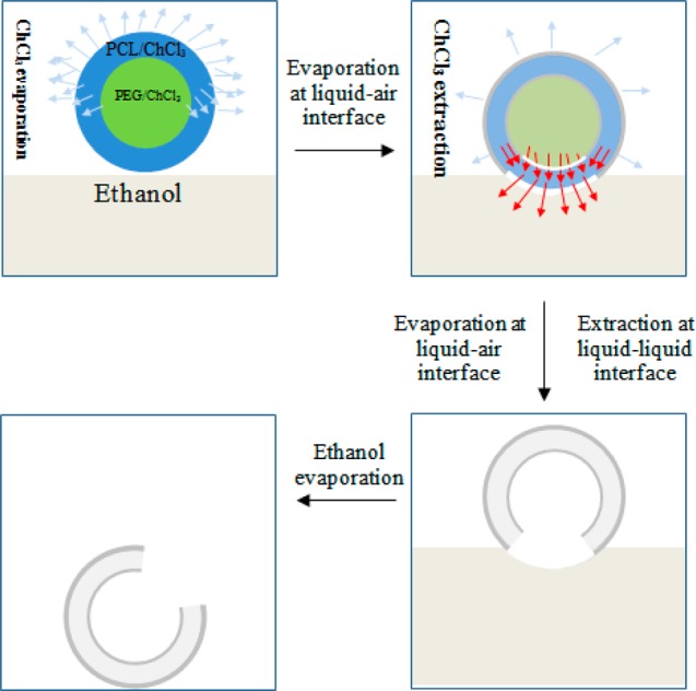
Schematic illustration of three proposed major steps involved in the formation of single-hole hollow microspheres. In the first step, core–shell microspheres undergo rapid solvent evaporation on their way from the spinneret to the ethanol bath. The evaporation of chloroform occurs at the sphere–air interface, which results in the loss of most chloroform and solidification of the PCL shell, considering its volatility and the 20 cm working distance from the spinneret to the ethanol bath collector. Once spheres are deposited on the surface of the ethanol bath, besides evaporation, chloroform extraction by ethanol occurs at the sphere–liquid interface, which becomes dominant. This extraction on the sphere–liquid interface results in a solvent gradient and thus an outward flux of chloroform, which dissolves the PCL shell and leads to the formation of a hole through the sphere wall. In the last step, after the ethanol is completely evaporated, hollow PCL spheres with a single hole in the surface are formed.
To confirm that only part of the microsphere was immersed in the ethanol bath, a calculation is done below to give the force of gravity (Fg) of a hollow PCL microsphere and its buoyancy force (FA) in the ethanol bath. Take as an illustration a hollow PCL microsphere produced using a 3.0/1.0 mL/h shell/core flow rate (Figure 6h, below), with diameter D = 14.9 μm (1.49 × 10⁻³ cm), wall thickness t = 0.25 μm (2.5 × 10⁻⁵ cm), and the density ρ and ρw of PCL and ethanol was 1.45 and 0.789 g/cm3, respectively. So, the hollow sphere total volume V = 4/3π(D/2)3 = 4/3 × 3.14 × (1.49/2 × 10–3 cm)3 = 1.73 × 10⁻⁹ cm3. If this hollow PCL sphere is entirely immersed in the ethanol bath, the resultant buoyancy force FA = ρwVg = (0.789 g/cm3) × (1.73 × 10–9 cm3) × (9.81 × 10–3 N/g) = 13.3 × 10⁻¹² N. The hollow sphere wall volume Vw = 4/3π(t/2)3 = 4/3 × 3.14 × (2.5 × 10–5 cm)3 = 0.65 × 10⁻¹³ cm3. So the force of gravity of hollow PCL spheres Fg = ρwVwg = (1.45 g/cm3) × (0.65 × 10–13 cm3) × (9.81 × 10–3 N/g) = 9.2 × 10⁻¹⁶ N.
Figure 6.

(a) Photograph of a microsphere tube (dash line indicating its longitudinal direction). (b, c) SEM micrographs showing the longitudinal view of the microsphere tube (circle indicating the wall boundary). (d) Inner surface of the microsphere tube. (e) Cross-sectional view of the microsphere tube. (f) SEM micrograph showing the hollow structure of PCL microspheres after cryo-sectioning. Representative SEM images used to measure the wall thickness of hollow PCL microspheres produced at the shell/core flow rate of (g) 3.0/1.5 mL/h, (h) 3.0/1.0 mL/h, and (i) 6.0/0.5 mL/h. The sphere size and wall thickness are expressed as mean ± standard deviation from 50 measurements. Experimental settings for the microsphere tube: applied voltage, 9.0 kV; working distance, 20 cm; shell/core flow rate, 3.0/1.0 mL/h.
It is obvious that the force of gravity Fg of hollow PCL spheres is drastically smaller than the buoyancy force FA that microsheres are subject to in the complete immersion case, which leads to PCL spheres floating in the ethanol bath.
Effect of Core Flow Rate on the Formation of Single-Hole Hollow PCL Microspheres
Previous studies have demonstrated that the core/shell solution concentration and processing parameters including flow rate and applied voltage play a key role in the formation of core–shell and spherical particles in co-electrospraying.22,36,42 In the present study, the core flow rate was investigated to determine its effect on spheres, especially the formation of single holes, since it is usually used to tune the inner diameters of hollow microspheres22 and co-electrospun hollow microfibers.29 As shown in Figure 4, when the core flow rate decreased, there were substantial differences in the hole size in the surface: the holes resulting from 0.2 mL/h (Figure 4b) and 0.05 mL/h (Figure 4c) were much smaller than those created from 1.0 mL/h (Figure 4c) and 0.5 mL/h (Figure 4a), or they were never formed. SEM micrographs also revealed that the microsphere size/shape changed when the core flow rate changed, while a shell flow rate of 3.0 mL/h was maintained. For example, larger spheres were present at 0.2 mL/h (Figure 4b) and nonspherical shapes (elongated droplets) appeared at 0.05 mL/h (Figure 4c). This result was consistent with Hwang et al.’s study that demonstrated that a poorly chosen core/shell flow rate ratio produces PCL–PS particles with irregular shape and sizes.36Figure 4d–f shows that the microspheres that were deposited on aluminum foil had no similar single hole in the sphere surface compared to those collected in ethanol, which was consistent with those from 1.0 mL/h (Figure 2a). We assume that the change in hole size may have a correlation with the flux of chloroform from the core solution during its extraction by ethanol. At higher inner flow rates, the flux of chloroform was increased and stronger, leading to the formation of holes with larger openings. To confirm our assumption, a shell solution with a higher PCL concentration (9 wt %) was used to prepare spheres, as a higher shell PCL component was expected to contribute to the holes in a similar way to the lower core flow rate. As shown in Figure 4g, no holes were observed in the surface of the majority of microspheres collected in the ethanol bath when the core flow rate was 0.2 mL/h, compared to the spheres in Figure 4b. Larger spheres (∼50 μm, inset in Figure 4h) were produced, as expected, but additionally, short protruding capillary-like structures were seen (∼2 μm inner diameter) on the sphere surface (Figure 4h). The increase in the overall sphere size and the presence of surface capillaries could be explained by the higher solution concentration not only providing more PCL but also facilitating a co-electrosprayed structure transition from spherical to fibrous shape, as seen in co-electrospraying of PCL–PS microspheres.36 It is also worth noting that there was another type of hole with a circular opening and smaller size, which was rarely seen on spheres collected in ethanol liquid but more likely to be seen on those deposited on aluminum foil (highlighted by circles in Figure 4f,i). This type of hole was also observed in previous studies on electrospraying of PCL spheres8 and co-electrospraying of PMSQ and PFH.42 The ambient conditions [temperature/relative humidity (RH)] for co-electrospraying were not controlled but monitored in this study, which were 5.5 °C/40.7% RH for 0.5 mL/h core flow rate (Figure 4a,d), 4.2 °C/41.2% RH for 0.2 mL/h core flow rate (Figure 4b,e), and 5.0 °C/36.5% RH for 0.05 mL/h core flow rate (Figure 4e,f). It is well accepted that temperature and humidity can affect solvent evaporation in electrospraying/co-electrospraying, which could result in the formation of the second type of hole, though the exact mechanism remains unclear.
Figure 4.

Effect of core flow rate on the formation of a surface hole on hollow PCL spheres collected on different substrates: (a–c) 0.5, 0.2, and 0.05 mL/h in an ethanol bath; (d–f) 0.5, 0.2, and 0.05 mL/h on aluminum foil; (g, h) spheres deposited in an ethanol bath (9 wt % PCL/chloroform shell solution, 0.2 mL/h core flow rate) and (i) on aluminum foil (9 wt % PCL/chloroform shell solution, 0.2 mL/h core flow rate). The inset in part h highlights the appearance of surface capillary-like structures under certain conditions. The inset in part i shows the surface hole on electrosprayed solid PCL spheres. Other co-electrospraying conditions: PCL/chloroform (5 wt %, shell) + PEG/chloroform (15 wt %, core); applied voltage, 9.0 kV; working distance, 20 cm; shell flow rate, 3.0 mL/h.
Effect of Core Solution on the Formation of Single-Hole PCL Hollow Microspheres
In order to investigate the effect of miscibility between core and shell solutions on the formation of the single-hole structure, PCL spheres were also prepared from the shell–core combination of PCL/chloroform (5 wt %)–PEG/water (15 wt %) and PEG/water+ethanol (15 wt %, 2/8 v/v) and were then collected in an ethanol bath and on aluminum foil using the core flow rates of 1.0, 0.5, 0.2, and 0.05 mL/h. The difference of core solution here from that previously used (PEG/chloroform) lies in the complete immiscibility (PEG/water) or partly miscibility (PEG/water–ethanol) with PCL/chloroform. It became more difficult to achieve a stable coaxial cone-jet process using PEG/water or PEG/water–ethanol as core fluid, especially when the core flow rate was higher, i.e., 1.0 and 0.5 mL/h, resulting in solution dripping from the coaxial spinneret. As shown in Figure 5a,c,e, PEG/water or PEG/water–ethanol core derived microspheres deposited in an ethanol bath, unlike those from PEG/chloroform core, had no single-hole structure in the surface but instead became more porous. However, such porous surfaces were not seen on the spheres collected on aluminum foil (Figure 5b,d), which had much smaller sizes than those deposited in the ethanol bath. It was also seen that spheres from PEG/water–ethanol production became less uniform, and elongated or tear-shaped droplets were present (Figure 5f) since the addition of ethanol into water increased the solution viscosity and decreased surface tension, which favored the transition from spheres to fibers.43 It has also been reported for electrospraying that the mixture of spherical, elongated, and/or tear-shaped particles was the result of the interplay among a number of factors, including jet formation, droplet breakup, solvent evaporation, and eventual particle solidification.44 Therefore, it is expected that the formation of a mixture of structures in co-electrospraying could become more complex due to the introduction of core solution.
Figure 5.

Effect of core solution on single-hole PCL microspheres: (a, b) 0.2 mL/h core flow rate, 15 wt % PEG/water core solution, collected in an ethanol bath and on aluminum foil; (c, d) 0.05 mL/h core flow rate, 15 wt % PEG/water, in an ethanol bath and aluminum foil; and (e, f) 0.2 mL/h core flow rate, 15 wt % PEG/water/ethanol (2/8 v/v) in an ethanol bath and on aluminum foil. Co-electrospraying settings: PCL/chloroform (5 wt %, shell); applied voltage, 9 kV; working distance, 20 cm; shell flow rate, 3.0 mL/h.
On the basis of the proposed mechanism in Figure 3, the results revealed in Figure 5e suggest that the core evaporation rate when using a core solvent of water or water/ethanol is lower than when chloroform is used and, more importantly, that these solvents do not dissolve PCL; these factors may explain why the hole formation in the microsphere surface is not observed here. However, water or water/ethanol (nonsolvent for PCL) in the core solution had to be only evaporated through the solidified PCL shell, but this evaporation was less complex than that (evaporation via hollow fibers shell and to outlet) occurring to the co-electrospinning of hollow PCL microfibers.23 The evaporation of the core solvent through the PCL shell, along with an ethanol bath, could contribute to the formation of a porous surface. In a previous study on electrospraying of PCL,8 it was found that PCL microspheres collected in a water bath became more porous and had larger sizes than those collected on an aluminum plate due to the presence of large pores in the spheres. This was thought to be a result of the decreasing interaction between PCL and chloroform by nonsolvent water, thus favoring the phase separation. This could also apply to our case and help explain the observed porous and larger-size co-electrosprayed PCL spheres in the ethanol bath collection.
Co-Electrospraying of Hollow PCL Microspheres without a Surface Hole and Their 3D Bulk Structure
In the previous section, we have shown that the core/shell solution pair of PEG in chloroform/PCL in chloroform achieved a stable co-electrospraying process. This pair was thus selected to produce the bulk microsphere samples.
Figure 6a shows a typical tube-shaped bulk microsphere sample fabricated after 1 h of co-electrospraying. The microsphere tube had a length and inner diameter of about 8 cm and 1 mm, respectively, and was cut in parallel and perpendicular directions for microstructural characterization. As shown in Figure 6b–d, microspheres on the outer tube wall were aggregated to neighboring ones, resulting in the formation of interconnected clusters of spheres with void spaces, but they tended to merge into a dense layer on the inner surface with a few microns thickness. As shown in Figure 6e, the wall of the microsphere tube was not uniform in thickness (thicker on top), which was due to the preferable deposition of microspheres on the top of the static wire electrode. While the inner diameter of the bulk sample depended on the diameter of the wire electrode, the thickness of the sample depended on the duration of co-electrospraying. These microspheres collected on the wire show a hollow structure after cryo-sectioning (Figure 6f), although spheres were deformed during the sectioning process due to the material’s ductility. In contrast, electrosprayed PCL microspheres were confirmed to be solid (see the inset in Figure 1a). Figure 6g–i shows representative cross-sectional images used to measure the wall thickness of hollow PCL microspheres produced using different shell/core flow rates of 3.0/1.5, 3.0/1.0, and 6.0/0.5 mL/h. These microspheres had a wall thickness of 0.19 ± 0.06, 0.25 ± 0.07, and 2.09 ± 0.82 μm (mean ± standard deviation), respectively, with the corresponding overall diameter of 15.1 ± 2.9, 14.9 ± 1.7, and 17.9 ± 2.1 μm, indicating that a higher shell/core flow rate ratio can result in a thicker wall, which is consistent with a previous study by Chang et al.22
In our previous studies, hollow microfibers with diameters of 3.3–15 μm produced by co-electrospinning were used to develop axon and cardiac-mimicking test objects (phantoms) for the validation of diffusion magnetic resonance imaging.29,45 Here hollow PCL microspheres were produced to mimic tumor cells that typically range from 10 to 20 μm,46 which could find application in the validation of tumor microstructure models in diffusion magnetic resonance imaging.47 Further work is in progress to prepare 3D bulk structures of PCL microspheres with various wall thicknesses. It is also noteworthy that the yield of the co-electrospraying process is low, but the yield can be enhanced by novel spinnerets.41,48−51
Nano-XCT, a Nondestructive High-Precision Characterization Technique
The external PCL wall could be clearly distinguished on phase-contrast imaging, as shown in Figure 7a. A typical cross-sectional 3D reconstruction of co-electrosprayed PCL microspheres after segmentation is shown in Figure 7b. The PCL formed the outer surface of the microspheres, leaving the majority of the volume unoccupied (core). From the measurements on the nano-XCT cross-sectional 3D reconstructed and segmented images (Figure 7b), the walls of the hollow PCL microspheres had a thickness of 307.3 ± 78.7 nm (mean ± standard deviation).
Figure 7.

(a) Transversal virtual cut of PCL microspheres showing XCT phase contrast based fringes. (b) Transversal virtual cut of PCL microspheres after shell segmentation using phase contrast based fringes. (c) 3D visualization of segmented hollow PCL microspheres. (d) 3D visualization of segmented hollow spheres and the corresponding orthogonal virtual cut. (e, f) SEM images showing the wall between merged microspheres.
Figure 7c,d shows 3D reconstructed images of hollow PCL microspheres after segmentation and the corresponding transversal virtual cut. As seen in Figure 7a,b,d, it seems that part of the spheres’ walls is not visible, particularly at the points where spheres meet. This observation could be caused by (1) neighboring hollow spheres having merged and therefore no separating wall is present; (2) the wall thickness may be less than the acquisition resolution, which was 64 nm/pixel; or (3) artifacts in the phase contrast data may be obscuring detail. It can be deduced from either possibility that wall thinning occurred during the sintering process. SEM images of microspheres after cryo-sectioning (Figure 7e,f) show that there are wall barriers between neighboring spheres. However, it should be pointed out that these SEM images do not correspond to the same spheres scanned by nano-XCT. This apparent contradiction between the SEM and phase-contrast CT regarding the status of walls between spheres may be due to imperfections in either of the imaging methods, and further work is required in order to unambiguously determine the presence or absence of these walls.
Conclusions
We have presented a direct co-electrospraying approach to fabricate hollow microspheres with a tunable surface hole from PCL as shell and PEG as core and their 3D bulk structure, which has not been demonstrated previously. This method is straightforward, rapid, and cost-effective, because it does not require expensive chemical agents and instruments. The microstructures of co-electrosprayed products were characterized using SEM and nano-XCT. It was demonstrated that the miscibility of the core/shell solution and the choice of collecting system played a key role in determining the microsphere structures. A miscible core/shell solution pair (PEG/chloroform and PCL/chloroform) achieved a more stable co-electrospraying process than other immiscible pairs (aqueous solution core) and thus produced spherical particles. It was also found that an ethanol bath collecting system led to the formation of single-hole hollow microspheres when PEG/chloroform was used as the core, which were not obtained on aluminum foil and copper wire collectors. A mechanism responsible for the transformation of the core/shell structure into single-hole hollow microspheres was proposed on the basis of the evaporation through the shell and extraction by ethanol of the core solution. Further study will be required on quantitatively controlling the hole size in the co-electrosprayed PCL microsphere surfaces as for previously reported PS and PMMA microspheres with controllable surface holes produced by low-temperature swelling.38
In addition to the more conventional production of a 2D microsphere layer on aluminum foil, a 3D microsphere sample was fabricated on a copper wire collector, which had interconnected sphere clusters throughout most of the structure but nearly merged together spheres on the inner surface. SEM and nano-XCT revealed the hollow structure of interconnected spheres and also the difference in wall thickness. There were wall barriers between merged neighboring spheres on SEM images, but these were not shown on nano-XCT, which motivates further work on characterizing these structures. This bulk microsphere construct can be potentially used as a tumor cell-mimicking structure (usually called phantom) for application in diffusion magnetic resonance imaging (MRI), as demonstrated in early experimental results.47 As a phantom material, one major advantage of PCL over other biodegradable polymers like PLGA and PLA lies in its long shelf life due to its long-term stability (up to 3–4 years).52 Although the size uniformity of hollow PCL microspheres is less important for a tumor cell-mimicking phantom, it is highly desirable for applications like drug delivery and encapsulation of therapeutic molecules and could be produced by using a coaxial spinneret system previously reported by Hwang and co-workers.36 Our current efforts include the production of tumor cell-mimicking hollow microspheres with variable sizes from different biopolymers, enabling us to determine the relationship between MR signals and microsphere sizes.
Acknowledgments
This work was supported by the CRUK-EPSRC Cancer Imaging Centre in Cambridge and Manchester (C8742/A18097).
Supporting Information Available
The Supporting Information is available free of charge on the ACS Publications website at DOI: 10.1021/acs.langmuir.7b01985.
A video of the co-electrospraying of hollow PCL microspheres (AVI)
The authors declare no competing financial interest.
Author Status
# P.L.H.C. and G.J.M.P. are joint senior authors.
Supplementary Material
References
- Jaworek A. Micro- and nanoparticle production by electrospraying. Powder Technol. 2007, 176 (1), 18–35. 10.1016/j.powtec.2007.01.035. [DOI] [Google Scholar]
- Li D.; Xia Y. Electrospinning of Nanofibers: Reinventing the Wheel?. Adv. Mater. 2004, 16 (14), 1151–1170. 10.1002/adma.200400719. [DOI] [Google Scholar]
- McKee M. G.; Wilkes G. L.; Colby R. H.; Long T. E. Correlations of Solution Rheology with Electrospun Fiber Formation of Linear and Branched Polyesters. Macromolecules 2004, 37 (5), 1760–1767. 10.1021/ma035689h. [DOI] [Google Scholar]
- Chen H.; Elabd Y. A. Polymerized Ionic Liquids: Solution Properties and Electrospinning. Macromolecules 2009, 42 (9), 3368–3373. 10.1021/ma802347t. [DOI] [Google Scholar]
- Moghe A. K.; Gupta B. S. Coaxial Electrospinning for Nanofiber Structures: Preparation and Applications. Polym. Rev. 2008, 48 (2), 353–377. 10.1080/15583720802022257. [DOI] [Google Scholar]
- Zhang L.; Huang J.; Si T.; Xu R. X. Coaxial Electrospray of Microparticles and Nanoparticles for Biomedical Applications. Expert Rev. Med. Devices 2012, 9 (6), 595–612. 10.1586/erd.12.58. [DOI] [PMC free article] [PubMed] [Google Scholar]
- Luo C. J.; Edirisinghe M. Core-Liquid-Induced Transition from Coaxial Electrospray to Electrospinning of Low-Viscosity Poly(lactide-co-glycolide) Sheath Solution. Macromolecules 2014, 47 (22), 7930–7938. 10.1021/ma5016616. [DOI] [Google Scholar]
- Wu Y.; Clark R. L. Controllable Porous Polymer Particles Generated by Electrospraying. J. Colloid Interface Sci. 2007, 310 (2), 529–535. 10.1016/j.jcis.2007.02.023. [DOI] [PubMed] [Google Scholar]
- Enayati M.; Ahmad Z.; Stride E.; Edirisinghe M. Size Mapping of Electric Field-assisted Production of Polycaprolactone Particles. J. R. Soc., Interface 2010, 7 (Suppl 4), S393–S402. 10.1098/rsif.2010.0099.focus. [DOI] [PMC free article] [PubMed] [Google Scholar]
- Bock N.; Dargaville T. R.; Woodruff M. A. Electrospraying of Polymers with Therapeutic Molecules: State of the art. Prog. Polym. Sci. 2012, 37 (11), 1510–1551. 10.1016/j.progpolymsci.2012.03.002. [DOI] [Google Scholar]
- Bock N.; Woodruff M. A.; Hutmacher D. W.; Dargaville T. R. Electrospraying, a Reproducible Method for Production of Polymeric Microspheres for Biomedical Applications. Polymers 2011, 3 (1), 131–149. 10.3390/polym3010131. [DOI] [Google Scholar]
- Guarino V.; Wan Abdul Khodir W. K.; Ambrosio L. Biodegradable Microspheres and Nanospheres by Electrospraying Techniques. J. Appl. Biomater. Funct. Mater. 2012, 10 (3), 191–196. 10.5301/JABFM.2012.10369. [DOI] [PubMed] [Google Scholar]
- Doshi N.; Zahr A. S.; Bhaskar S.; Lahann J.; Mitragotri S. Red Blood Cell-mimicking Synthetic Biomaterial Particles. Proc. Natl. Acad. Sci. U. S. A. 2009, 106 (51), 21495–21499. 10.1073/pnas.0907127106. [DOI] [PMC free article] [PubMed] [Google Scholar]
- Hayashi K.; Ono K.; Suzuki H.; Sawada M.; Moriya M.; Sakamoto W.; Yogo T. Electrosprayed Synthesis of Red-Blood-Cell-Like Particles with Dual Modality for Magnetic Resonance and Fluorescence Imaging. Small 2010, 6 (21), 2384–2391. 10.1002/smll.201000399. [DOI] [PubMed] [Google Scholar]
- Ji S. W.; Lee I. Recent Progress on the Preparation Processes of Hollow Polymer Nano and Microspheres. Curr. Trends Polym. Sci. 2011, 15, 63–75. [Google Scholar]
- Jang T.-S.; Lee E.-J.; Kim H.-E.; Koh Y.-H. Hollow Porous Poly(ε-caprolactone) Microspheres by Emulsion Solvent Extraction. Mater. Lett. 2012, 72, 157–159. 10.1016/j.matlet.2011.12.105. [DOI] [Google Scholar]
- Loscertales I. G.; Barrero A.; Guerrero I.; Cortijo R.; Marquez M.; Gañán-Calvo A. M. Micro/nano Encapsulation via Electrified Coaxial Liquid Jets. Science 2002, 295, 1695–1698. 10.1126/science.1067595. [DOI] [PubMed] [Google Scholar]
- Mei F.; Chen D.-R. Investigation of Compound Jet Electrospray: Particle encapsulation. Phys. Fluids 2007, 19 (10), 103303–1–10. 10.1063/1.2775976. [DOI] [Google Scholar]
- Chen H.; Zhao Y.; Song Y.; Jiang L. One-Step Multicomponent Encapsulation by Compound-Fluidic Electrospray. J. Am. Chem. Soc. 2008, 130 (25), 7800–7801. 10.1021/ja801803x. [DOI] [PubMed] [Google Scholar]
- Jing Y.; Zhu Y.; Yang X.; Shen J.; Li C. Ultrasound-Triggered Smart Drug Release from Multifunctional Core–Shell Capsules One-Step Fabricated by Coaxial Electrospray Method. Langmuir 2011, 27 (3), 1175–1180. 10.1021/la1042734. [DOI] [PubMed] [Google Scholar]
- Koo S. Y.; Cha K. H.; Song D.-G.; Chung D.; Pan C.-H. Microencapsulation of Peppermint Oil in an Alginate–pectin Matrix using a Coaxial Electrospray System. Int. J. Food Sci. Technol. 2014, 49 (3), 733–739. 10.1111/ijfs.12358. [DOI] [Google Scholar]
- Chang M.-W.; Stride E.; Edirisinghe M. Controlling the Thickness of Hollow Polymeric Microspheres Prepared by Electrohydrodynamic Atomization. J. R. Soc., Interface 2010, 7 (Suppl 4), S451–S460. 10.1098/rsif.2010.0092.focus. [DOI] [PMC free article] [PubMed] [Google Scholar]
- Dror Y.; Salalha W.; Avrahami R.; Zussman E.; Yarin A. L.; Dersch R.; Greiner A.; Wendorff J. H. One-Step Production of Polymeric Microtubes by Co-electrospinning. Small 2007, 3 (6), 1064–1073. 10.1002/smll.200600536. [DOI] [PubMed] [Google Scholar]
- Zhou F.-L.; Hubbard P. L.; Eichhorn S. J.; Parker G. J. M. Jet Deposition in Near-field Electrospinning of Patterned Polycaprolactone and Sugar-polycaprolactone Core–shell Fibres. Polymer 2011, 52 (16), 3603–3610. 10.1016/j.polymer.2011.06.002. [DOI] [Google Scholar]
- Jana S.; Zhang M. Fabrication of 3D Aligned Nanofibrous Tubes by Direct Electrospinning. J. Mater. Chem. B 2013, 1 (20), 2575–2581. 10.1039/c3tb20197j. [DOI] [PubMed] [Google Scholar]
- Soffer L.; Wang X.; Zhang X.; Kluge J.; Dorfmann L.; Kaplan D. L.; Leisk G. Silk-Based Electrospun Tubular Scaffolds for Tissue-Engineered Vascular Grafts. J. Biomater. Sci., Polym. Ed. 2008, 19 (5), 653–664. 10.1163/156856208784089607. [DOI] [PMC free article] [PubMed] [Google Scholar]
- McCann J. T.; Li D.; Xia Y. Electrospinning of Nanofibers with Core-sheath, Hollow, or Porous structures. J. Mater. Chem. 2005, 15 (7), 735–738. 10.1039/b415094e. [DOI] [Google Scholar]
- Xu Y.; Hanna M. A. Morphological and Structural Properties of Two-phase Coaxial Jet Electrosprayed BSA-PLA Capsules. J. Microencapsulation 2008, 25 (7), 469–477. 10.1080/02652040802049513. [DOI] [PubMed] [Google Scholar]
- Zhou F.-L.; Hubbard P. L.; Eichhorn S. J.; Parker G. J. M. Coaxially Electrospun Axon-Mimicking Fibers for Diffusion Magnetic Resonance Imaging. ACS Appl. Mater. Interfaces 2012, 4 (11), 6311–6316. 10.1021/am301919s. [DOI] [PubMed] [Google Scholar]
- Hsu C.-M.; Shivkumar S. Nano-sized Beads and Porous Fiber Constructs of Poly(ε-caprolactone) Produced by Electrospinning. J. Mater. Sci. 2004, 39 (9), 3003–3013. 10.1023/B:JMSC.0000025826.36080.cf. [DOI] [Google Scholar]
- CAMEO Chemicals Database of Hazardous Materials. Chloroform Datasheet. http://cameochemicals.noaa.gov/chris/CRF.pdf.
- Than P.; Preziosi L.; Josephl D. D.; Arney M. Measurement of Interfacial Tension between Immiscible Liquids with the Spinning Road Tensiometer. J. Colloid Interface Sci. 1988, 124 (2), 552–559. 10.1016/0021-9797(88)90191-9. [DOI] [Google Scholar]
- Sun Z.; Zussman E.; Yarin A. L.; Wendorff J. H.; Greiner A. Compound Core–Shell Polymer Nanofibers by Co-Electrospinning. Adv. Mater. 2003, 15 (22), 1929–1932. 10.1002/adma.200305136. [DOI] [Google Scholar]
- Han D.; Boyce S. T.; Steckl A. J. Versatile Core-Sheath Biofibers using Coaxial Electrospinning. MRS Online Proc. Libr. 2008, 1094, DD06–02. 10.1557/PROC-1094-DD06-02. [DOI] [Google Scholar]
- Cao Y.; Wang B.; Wang Y.; Lou D. Polymer-controlled Core-shell Nanoparticles: a Novel Strategy for Sequential Drug Release. RSC Adv. 2014, 4 (57), 30430–30439. 10.1039/C4RA03610G. [DOI] [Google Scholar]
- Hwang Y. K.; Jeong U.; Cho E. C. Production of Uniform-Sized Polymer Core–Shell Microcapsules by Coaxial Electrospraying. Langmuir 2008, 24 (6), 2446–2451. 10.1021/la703546f. [DOI] [PubMed] [Google Scholar]
- Zhou F.-L.; Hubbard Cristinacce P. L.; Eichhorn S. J.; Parker G. J. M. Preparation and Characterization of Polycaprolactone Microspheres by Electrospraying. Aerosol Sci. Technol. 2016, 50 (11), 1201–1215. 10.1080/02786826.2016.1234707. [DOI] [PMC free article] [PubMed] [Google Scholar]
- Im S. H.; Jeong U.; Xia Y. Polymer Hollow Particles with Controllable Holes in Their Surfaces. Nat. Mater. 2005, 4 (9), 671–675. 10.1038/nmat1448. [DOI] [PubMed] [Google Scholar]
- Guan G.; Zhang Z.; Wang Z.; Liu B.; Gao D.; Xie C. Single-Hole Hollow Polymer Microspheres toward Specific High-Capacity Uptake of Target Species. Adv. Mater. 2007, 19 (17), 2370–2374. 10.1002/adma.200700984. [DOI] [Google Scholar]
- Naidoo K.; Rolfes H.; Easton K.; Moolman S.; Chetty A.; Richter W.; Nilen R. An Emulsion Preparation for Novel Micro-porous Polymeric Hemi-shells. Mater. Lett. 2008, 62 (2), 252–254. 10.1016/j.matlet.2007.05.012. [DOI] [Google Scholar]
- Mahalingam S.; Raimi-Abraham B. T.; Craig D. Q. M.; Edirisinghe M. Formation of Protein and Protein–Gold Nanoparticle Stabilized Microbubbles by Pressurized Gyration. Langmuir 2015, 31 (2), 659–666. 10.1021/la502181g. [DOI] [PubMed] [Google Scholar]
- Chang M.-W.; Stride E.; Edirisinghe M. A New Method for the Preparation of Monoporous Hollow Microspheres. Langmuir 2010, 26 (7), 5115–5121. 10.1021/la903592s. [DOI] [PubMed] [Google Scholar]
- Fong H.; Chun I.; Reneker D. H. Beaded Nanofibers Formed during Electrospinning. Polymer 1999, 40 (16), 4585–4592. 10.1016/S0032-3861(99)00068-3. [DOI] [Google Scholar]
- Scholten E.; Dhamankar H.; Bromberg L.; Rutledge G. C.; Hatton T. A. Electrospray as a Tool for Drug Micro- and Nanoparticle Patterning. Langmuir 2011, 27 (11), 6683–6688. 10.1021/la201065n. [DOI] [PubMed] [Google Scholar]
- Teh I.; Zhou F.-L.; Hubbard Cristinacce P. L.; Parker G. J. M.; Schneider J. E. Biomimetic Phantom for Cardiac Diffusion MRI. Journal of Magnetic Resonance Imaging 2016, 43 (3), 594–600. 10.1002/jmri.25014. [DOI] [PMC free article] [PubMed] [Google Scholar]
- Jiang X.; Li H.; Xie J.; McKinley E. T.; Zhao P.; Gore J. C.; Xu J. In vivo Imaging of Cancer Cell Size and Cellularity using Temporal Diffusion Spectroscopy. Magn. Reson. Med. 2017, 78 (1), 156–164. 10.1002/mrm.26356. [DOI] [PMC free article] [PubMed] [Google Scholar]
- McHugh D. J.; Zhou F.-L.; Cristinacce P. L. H.; Naish J. H.; Parker G. J. M.. Ground Truth for Diffusion MRI in Cancer: A Model-based Investigation of a novel Tissue-mimetic Material. In Information Processing in Medical Imaging; Ourselin S., Alexander D., Westin C. F., Cardoso M., Eds.; Lecture Notes in Computer Science Vol. 9123; Springer, 2015; pp 179–190 10.1007/978-3-319-19992-4_14. [DOI] [PubMed] [Google Scholar]
- Vysloužilová L.; Valtera J.; Pejchar K.; Beran J.; Lukas D. Design of Coaxial Needleless Electrospinning Electrode with Respect to the Distribution of Electric Field. Appl. Mech. Mater. 2014, 693, 394–399. 10.4028/www.scientific.net/AMM.693.394. [DOI] [Google Scholar]
- Labbaf S.; Ghanbar H.; Stride E.; Edirisinghe M. Preparation of Multilayered Polymeric Structures Using a Novel Four-Needle Coaxial Electrohydrodynamic Device. Macromol. Rapid Commun. 2014, 35 (6), 618–623. 10.1002/marc.201300777. [DOI] [PMC free article] [PubMed] [Google Scholar]
- Yan X.; Marini J.; Mulligan R.; Deleault A.; Sharma U.; Brenner M. P.; Rutledge G. C.; Freyman T.; Pham Q. P. Slit-Surface Electrospinning: A Novel Process Developed for High-Throughput Fabrication of Core-Sheath Fibers. PLoS One 2015, 10 (5), e0125407. 10.1371/journal.pone.0125407. [DOI] [PMC free article] [PubMed] [Google Scholar]
- Olvera-Trejo D.; Velasquez-Garcia L. F. Additively Manufactured MEMS Multiplexed Coaxial Electrospray Sources for High-throughput, Uniform Generation of Core-shell Microparticles. Lab Chip 2016, 16 (21), 4121–4132. 10.1039/C6LC00729E. [DOI] [PubMed] [Google Scholar]
- Woodruff M. A.; Hutmacher D. W. The Return of a Forgotten Polymer—Polycaprolactone in the 21st Century. Prog. Polym. Sci. 2010, 35 (10), 1217–1256. 10.1016/j.progpolymsci.2010.04.002. [DOI] [Google Scholar]
Associated Data
This section collects any data citations, data availability statements, or supplementary materials included in this article.