Abstract
A horizontal multi-purpose microbeam system with a single electrostatic quadruplet focusing lens has been developed at the Columbia University Radiological Research Accelerator Facility (RARAF). It is coupled with the RARAF 5.5 MV Singleton accelerator (High Voltage Engineering Europa, the Netherlands) and provides micrometer-size beam for single cell irradiation experiments. It is also used as the primary beam for a neutron microbeam and microPIXE (particle induced x-ray emission) experiment because of its high particle fluence. The optimization of this microbeam has been investigated with ray tracing simulations and the beam spot size has been verified by different measurements.
I. Introduction
Single-cell irradiation microbeams are playing an important role in elucidating inter-cellular and intra-cellular damage-signal transduction [1, 2, 3]. Following the other microbeam developments at RARAF, a new horizontal multi-purpose microbeam system has been designed and built. It can operate as a conventional charged particle microbeam to perform single cell irradiations with the beam directly focused to impinge on biological samples, e.g., single cells or tissue. On the other hand, it can be used for the first stage of a neutron microbeam [4, 5] and a microPIXE (particle induced x-ray emission) system.
The horizontal beam line configuration was chosen due to the beam line arrangement at RARAF. The beam focusing is accomplished with a single, customized electrostatic quadrupole quadruplet lens and a pair of beam collimation apertures. The verification and optimization of this horizontal microbeam was performed based on a 1.885 MeV proton beam. The beam acceptance has been optimized with different collimation apertures to allow a higher proton beam current (about 5 nA measured on the target) being used for the neutron microbeam irradiation and microPIXE experiment.
II. System configuration
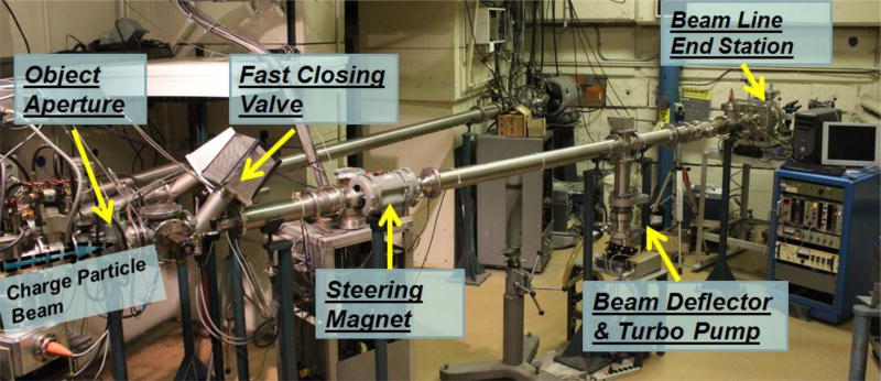
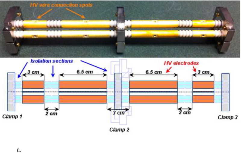
This newly assembled horizontal microbeam system is located inside the RARAF accelerator hall (Fig. 1). The whole length of the beam line from ion beam object aperture to the Havar vacuum exit window (or LiF target for neutron microbeam) is about 6.4 meters. An optimized beam acceptance configuration has been designed to maximize the throughput of radiation experiments. The focusing lens is a custom-made electrostatic quadrupole quadruplet which gives a symmetrical beam spot pattern. The design of the lens is shown in figure 2a.
Figure 1.
The newly assembled horizontal microbeam system at the Radiological Research Accelerator Facility (RARAF), Columbia University.
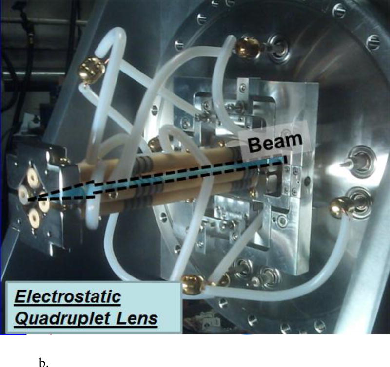
Figure 2.
a. Electrostatic quadrupole quadruplet focusing lens
b. Lens mounted inside a vacuum chamber
There are two short quadrupoles and two long quadrupoles in this quadruplet lens. The short quadrupole length is 3 cm and the long quadrupole length is 6 cm. The isolated section length between adjacent quadrupoles is 2 cm and the bore radius of the quadrupole is 1 cm. The electrostatic quadrupole-quadruplet was manufactured in the RARAF instrument shop using precision-ground ceramic rods as the basic structure like our previous designs [6]. Grooves are cut in the surface to define the electrode lengths and the spacing between them. Platinum ions were subsequently implanted to tailor the surface resistivity. Gold deposition coatings were then applied on the quadrupole elements and the lens rods were collectively assembled using precision techniques to form the final lens.
Then, the entire lens has been mounted on a vertical pivot plate which allows adjustment in four directions for beamline alignment (Fig. 2b). The individual electrodes are connected to four 10 kV high voltage vacuum feedthroughs using “egg”-shaped wire connectors. The voltages on the quadrupoles are arranged in a ‘+A,−B, +B,−A’ configuration (A, B are voltages and the polarities are alternated), which can balance the beam convergence and divergence in both the vertical and horizontal axes. A quadruple 10 kV power supply (CPS Inc, Tigard, OR) was used to control the voltages on the lens with very small peak-to-peak ripple (0.1%). The object distance (distance between the beam object aperture and the front surface of the quadruplet lens) is about 5.8 m and the image distance (distance between the end of the lens and the focal spot) is about 35 cm. To minimize the effects of scattering, there is an additional aperture inside the beam line attached to the first quadrupole to limit the angular divergence of the beam.
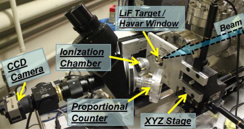
The lens and a vacuum break sensor are contained in a 30 cm diameter vacuum chamber. Beam diagnostic/handling devices (e.g., steering magnet, shutter, beam positioning diagnostic slides) and other vacuum protection devices (e.g., fast closing valve and beam line vacuum baffle) are installed in the beamline upstream of the lens. Two particle counters have been constructed for detecting particles which have passed through the microbeam exit window. The general design of the detectors is an aluminum shell with a clamp at the top that attaches the detector to the objective lens of the horizontal customized microscope used for observing the cells to be irradiated (Fig 3). Both counters are filled with P-10 (90% Ar, 10% CH4) gas at atmospheric pressure that is confined to the counter with optically transparent window. The first counter has a relatively large diameter (0.8 mm) collector electrode and can be used as an ionization chamber for high-current proton beam tests. The other one has a small diameter (25 µm) center electrode and a field-shaping helical electrode (60 µm) that produce a high gas gain, making it suitable for detecting ionization of individual protons or α particles with MeV energies. The first detector is biased with a +50 V floating power supply and the second one is biased to 800 V with a Canberra high voltage NIM module. In order to maximize the signal, the height of the detector body was designed to provide the longest path length for the particles within the focal length of the objective lens. A Nikon M Plan 40 ELWD (10.1 mm working distance) objective is used to adapt these detectors. The imaging system includes a customized long-travel horizontal microscope coupled with a fast EO USB2.0 CMOS camera (Edmund Optics Inc, Barrington, NJ). The sample dishes are handled by a USB-controlled 3D motorized stage (Thorlabs Inc, Newton, NJ). A customized cell dish holder has been mounted on the stage vertically. During the irradiation, the cell samples can be pre-scanned and identified by an integrated image analysis code and then be positioned by a XYZ stage system. Following the protocol, the selected particle beam is monitored to control the irradiation. In high current measurement mode, the ion-beam current is measured with the first detector (ionization chamber) and an ORTEC 439 current digitizer (AMETEK Inc, Berwyn, PA), which converts ionization current to pulses. In pulse counting mode, the particles are counted individually with the second detector (P10 gas proportional counter) and a data acquisition system (DAQ) system including an ORTEC 142 preamp, ORTEC 572 amplifier and ORTEC 570 single channel analyzer. Both systems use a CyberResearch CYCTM05 PCI counter card (CyberResearch Inc, Branford, CT) for computer control. The lens voltages are controlled with a CyberResearch CYDDA 08HRP DAC card (CyberResearch Inc, Branford, CT). A computer control-code written in Visual Basic automates beam scanning, particle detection, and stage handling.
Figure 3.
Microbeam detection and imaging system
III. Beam Performance Optimization
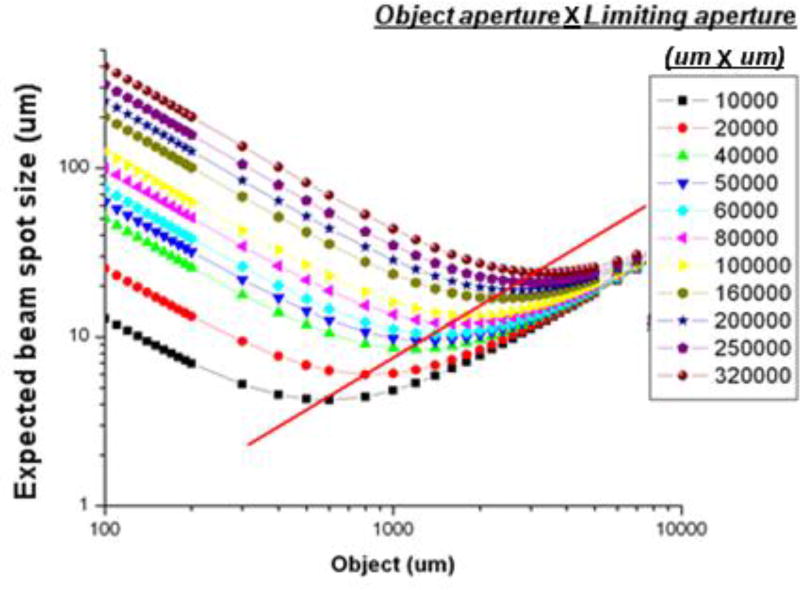
To optimize the microbeam’s focusing performance, a series of ray tracing simulations for a 1.885 MeV proton beam have been conducted using the program GIOS [7]. With a voltage of 6.2 kV on the long poles of the quadruplet lens and 5.8 kV on the short poles for this proton beam, the demagnification of quadruplet lens of this microbeam system was calculated to be about 11 at the targeted focal plane, which is 35 cm away from the end of quadruplet. The effective fringe field length is equal to the real pole geometric length plus an extended pole gap length [8]. However, the beam spot size at the focal plane is not only determined by the demagnification but also the geometry and chromatic aberrations. The present arrangement of polarities and field strengths (+A−B+B−A) makes the spherical aberrations in the lens system equal in both vertical and horizontal direction. The beam current is determined by the beam acceptance, which is geometrically defined by the beam divergence between the object aperture and the second collimator aperture located in front of the lens. A series of calculated curves show that the beam spot size reduction depends on reducing both the object aperture and the second collimator aperture. The minimum beam spot size is characterized in figure 4 according to the same beam acceptance (the size of object aperture times the size of limiting aperture). The solid straight line indicates the parameters to provide the best performance of this microbeam system.
Figure 4.
Proton microbeam system optimization calculation results (Each curve represents a set of calculation with the same acceptance of the collimation system. The smallest beam spots of each curve are fitted with a solid line)
IV. Verification Measurements
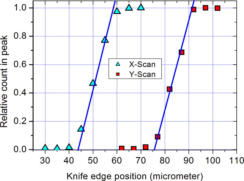
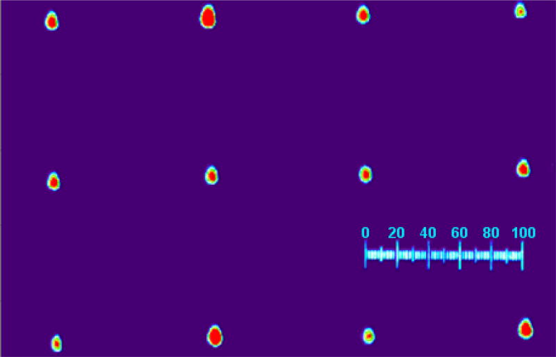
Using the beam optimization calculation results, we optimized the system and then performed a few beam spot size measurements. The beam spot size measurements were conducted with a 1.885 MeV proton beam. A 25 µm thick tantalum metal strip with a sharp edge was scanned across the beam vertically at the position of the focal plane using the precision stage with 0.1µm/step. For high-current proton beam measurements, a 0.5 nA beam passing through the 3 µm thick Havar foil vacuum window has been measured at the end of the beamline with a Keithley electrometer (Keithley Instruments, Inc. Cleveland, Ohio) which regulated the beam current. When the thin Ta “knife edge” strip was moved to eclipse the particle beam, those particles impinging on the strip surface are stopped, so the change of the detected particle signal gives a detailed beam profile in one dimension. This procedure was then repeated to obtain the beam profile in the orthogonal direction. The water cooled ion beam object aperture was set to about 1.2 mm in both x and y direction. Additionally, a 50 µm diameter beam-divergence collimator aperture, mounted on the front surface of the first qudrupole of the lens, was installed to provide the best performance according to the simulation analysis. With this 5 nA proton beam passing the exit window, the beam spot profile was measured to be about 15 by 15 µm with the ionization detector and ORTEC 490 current digitizer – see figure 5. A linear fit of the current vs. stage position is extrapolated to 0% and 100% and the difference of the stage positons between these two points is taken as the full width of the beam in that direction. Another test with a CR-39 emulsion has been conducted. In this case, the beam produced a grid pattern in 100 µm steps. The small burned marks on CR-39 are shown in figure 6. The typical size of those marks agrees with our scan measurement result. All of the beam configuration parameters were chosen according the optimized points from figure 4. The ion-beam focus measurements agree well with the calculations (with 1200 µm object aperture and 50 µm limiting aperture) and indicate that this beam is ready for cell irradiation, microPIXE and neutron microbeam experiments.
Figure 5.
Proton Beam Size Measurement Results (a linear fit of the relative count rate vs. stage position is extrapolated to 0% and 100% and the difference of the stage positons between these two points is taken as the full width of the beam in that direction)
Figure 6.
Proton Irradiation pattern on CR-39 (with a 100 µm scale)
V. Summary
For radiobiology studies, ion microbeam systems [9, 10 and 11] that have been developed in the last decade allow the irradiation of small structures such as the nuclei of cultured cells growing in a petri dish using a beam of energetic ions produced in an accelerator and then confined to a few micron diameter. A typical experiment is to allow one or a few ions to pass through each target that has been located and placed in the path of the beam [12]. However, the current developed horizontal microbeam is aiming to produce a novel secondary particle microbeam (neutron microbeam) or to conduct a microanalysis (microPIXE) which all require a high initial ion beam (proton beam mostly) current. To fulfill this special goal, we have constructed and optimized a horizontal multi-purpose microbeam system at RARAF. It’s demonstrated to focus 1.885 MeV protons to a diameter about 15 µm. The system is not only for single irradiation but also provides a relative high-current beam (0.5 nA) option for the development of a neutron microbeam and microPIXE experiment.
Acknowledgments
This work was supported by the National Institute of Biomedical Imaging and Bioengineering (NIBIB grant 8P41EB002033).
Footnotes
Publisher's Disclaimer: This is a PDF file of an unedited manuscript that has been accepted for publication. As a service to our customers we are providing this early version of the manuscript. The manuscript will undergo copyediting, typesetting, and review of the resulting proof before it is published in its final citable form. Please note that during the production process errors may be discovered which could affect the content, and all legal disclaimers that apply to the journal pertain.
References
- 1.Zhou H, Ivanov VN, Gillespie J, Geard CR, Amundson SA, Brenner DJ, Yu Z, Lieberman HB, Hei TK. Mechanism of radiation-induced bystander effect: role of the cyclooxygenase-2 signaling pathway. PNAS. 2005;102:14641–14646. doi: 10.1073/pnas.0505473102. [DOI] [PMC free article] [PubMed] [Google Scholar]
- 2.Zhou H, Randers-Pehrson G, Geard CR, Brenner DJ, Hall EJ, Hei TK. Interaction between radiation-induced adaptive response and bystander mutagenesis in mammalian cells. Radiat. Res. 2003;160:512–516. doi: 10.1667/rr3083. [DOI] [PMC free article] [PubMed] [Google Scholar]
- 3.Brenner DJ, Hall EJ. Microbeams: a potent mix of physics and biology. Radiat. Prot. Dosimetry. 2002;99:283–286. doi: 10.1093/oxfordjournals.rpd.a006785. [DOI] [PubMed] [Google Scholar]
- 4.Xu Yanping, Garty Guy, Marino Stephen A, Massey Thomas N, Randers-Pehrson Gerhard, Johnson Gary W, Brenner David J. Novel neutron sources at the Radiological Research Accelerator Facility. Journal of Instrumentation. 2012 Mar; doi: 10.1088/1748-0221/7/03/C03031. [DOI] [PMC free article] [PubMed] [Google Scholar]
- 5.Xu Yanping, Randers-Pehrson Gerhard, Marino Stephen A, Bigelow Alan W, Akselrod Mark S, Sykora Jeff G, Brenner David J. An accelerator-based neutron microbeam system for studies of radiation effects. Radiation Protection Dosimetry. 2011 Jun;145(4):373–6. doi: 10.1093/rpd/ncq424. [DOI] [PMC free article] [PubMed] [Google Scholar]
- 6.Randers-Pehrson Gerhard, Johnson Gary W, Marino Stephen A, Xu Yanping, Dymnikov Alexander D, Brenner David J. The Columbia University sub-micron charged particle beam. Nucl. Instrum. Methods Phys. Res A. 2009 Oct 11;609(2–3) doi: 10.1016/j.nima.2009.08.041. [DOI] [PMC free article] [PubMed] [Google Scholar]
- 7.Wollnik H, Brezina J, Geisse C. GIOS - A Program for the Design of Ion Optical Systems. Physikalisches Institut, Universität Giessen; D-6300 Giessen: 1998. [Google Scholar]
- 8.Grime GW, Watt F. Beam Optics of Quadrupole Probe-Forming System. Adam Hilger; Bristol, UK: 1984. [Google Scholar]
- 9.Barberet Ph, Balana A, Incerti S, Michelet-Habchi C, Moretto Ph, Pouthier Th. Development of a focused charged particle microbeam for the irradiation of individual cells. Rev. Sci. Instru. 2005;76:015101. [Google Scholar]
- 10.Grime GW, Abraham MH, Marsh MA. The new external beam facility of the Oxford scanning proton microprobe. Nucl. Instrum. Methods Phys. Res. B181(2001):66–70. [Google Scholar]
- 11.Greif KD, Brede HJ, Frankenberg D, Giesen U. The PTB single ion microbeam for irradiation of living cells. Nucl. Instrum. Methods Phys. Res. 2004;B217:505. [Google Scholar]
- 12.Xu Yanping, Zhang Bo, Messerli Mark, Randers-Pehrson Gerhard, Hei Tom K, Brenner David J. Metabolic oxygen consumption measurement with a single-cell biosensor after microbeam irradiation. Radiation and Environmental Biophysics. 2015 Mar;54(1):137–44. doi: 10.1007/s00411-014-0574-1. Epub 2014 Oct 22. [DOI] [PMC free article] [PubMed] [Google Scholar]


