Abstract
Materials with high dielectric constant (HDC) have been used in high field MRI to decrease specific absorption rate (SAR), increase magnetic field intensity, and increase signal-to-noise ratio. In previous studies, the HDC materials were placed inside the RF coil decreasing the space available. This study describes an alternative approach that considers an HDC-based sleeve placed outside the RF coil. The effects of an HDC on the electromagnetic (EM) field were studied using numerical simulations with a coil unloaded and loaded with a human head model. In addition, experimental EM measurements at 128 MHz were performed inside a custom-made head coil, fitted with a distilled water sleeve. The numerical simulations showed up to 40% decrease in maximum 10 g-avg. SAR on the surface of the head model with an HDC material of barium titanate. Experimental measurements also showed up to 20% decrease of maximum electric field using an HDC material of distilled water. The proposed method can be incorporated in the design of high field transmit RF coils.
Index Terms: Barium titanate, birdcage coil, coil design, distilled water, finite-difference time domain (FDTD), specific absorption rate (SAR)
I. Introduction
Magnetic resonance imaging (MRI) is widely used in scientific research and clinical diagnosis because of versatile soft tissue contrast, and the absence of reported harmful effects in clinical practice. However, high field (> 3 T) MRI is typically characterized by an increased inhomogeneity of radio frequency (RF) magnetic field (B1 field) and potential safety concerns related to increased RF energy absorbed by the subject. The International Electrotechnical Commission [1] has issued guidelines limiting the specific absorption rate (SAR), which is the parameter used to characterize the energy absorbed by the subject during an MRI. Therefore, it is desirable to minimize SAR, with improved B1 field uniformity and increased SNR in the field of view (FOV). One of the methods proposed to achieve these goals is based on the use of high dielectric constant (HDC) materials [2]–[13]. Yang et al. recently proposed a method of decreasing RF power required for a given flip angle resulting in lower SAR, higher SNR, and improved B1 field uniformity at 3 and 7 T head imaging [2]–[5]. The method proposed by Yang was based on the use of HDC materials placed between the RF coil and the human model (i.e., “coil-to-sample” space). Neufeld et al. [6] proposed a similar method to improve sensitivity and SNR using an HDC material located in the coil-to-sample space at 8.4 T. In the study, an HDC material of deuterium oxide (D2O), with relative permittivity εr = 78, was used. The study showed an improvement in the SNR of about 24%, obtained by manipulating the circulation of electric field within the coil with the HDC material. Other experimental and numerical studies have been performed for high field MRI and MR spectroscopy [8] with several different HDC materials, including distilled water [4], D2O [6], calcium titanate (CaTiO3) [10] and barium titanate (BaTiO3) [2], [7]. The electrical permittivity of these materials ranges between 78 [6] and 515 [7], the latter being much higher compared to biological tissues. For comparison, the average εr of the brain at 128 MHz, for example, is approximately 63 [14], [15].
Based on previous research, a novel method is herein introduced to decrease the electric field and SAR by placing an HDC material outside of the RF coil, rather than within the coil-to-sample space. Numerical simulations based on the finite-difference time domain (FDTD) algorithm with a human head model and two different HDC materials of BaTiO3 and distilled water were performed to demonstrate the shielding effect. This effect was also experimentally verified by direct measurements of electric field amplitude using a birdcage RF coil and a distilled water dielectric sleeve.
II. Theory
The total electric field (E) in a sample loading an RF coil is composed of conservative electric field (Ec), caused by the scalar electric potential (ϕ) in the coil winding, and magnetically induced electric field (Ei). The total electric field can then be expressed as follows [16], [17]:
| (1) |
where A is the vector magnetic potential (Wb/m).
In order to reduce the SAR and increase SNR, the total electric field needs to be minimized. When an HDC material oriented along the longitudinal axis of the RF coil is added outside the coil, an additional electrical potential is generated with opposite direction of the original one and partially shields the load in region of interest (ROI) from the Ec. This effect is valid under the assumption of no significant wavelength effects [18].
The magnetic field generated by an RF coil in the MRI can be explained using Ampere’s law [3], [4], [7], [10]
| (2) |
where Jc is the conduction current, Jd is the displacement current, i.e., secondary field source supporting the propagation of RF electromagnetic field, μ is the magnetic permeability (H/m), , ω is the angular frequency (rad/s), and ε0 = 8.854 × 10⁻¹² F/m is the electrical permittivity in free space. Additionally, the is defined as , where Bx and By are the complex amplitudes of x- and y-oriented RF magnetic fields, respectively [19].
Near the RF coil, because of the very high conductivity of the copper (σ = 5.8 × 10⁷ S/m) used to build the coil, the dominant source of magnetic field is Jc. However, within the human head the ratio of ‖Jc‖/‖Jd‖ is much lower. For example, at 128 MHz, ‖Jc‖/‖Jd‖ is around 1.03 because the average εr of the brain is approximately 63 and the average σ is approximately equal to 0.46 S/m [15]. Thus, inside the human head, Jd is responsible for about 50% of the total B1. Conversely, the presence of an HDC material generates a high value of Jd; therefore, the ratio ‖Jc‖/‖Jd‖ would be much less than 1 (e.g., ‖Jc‖/‖Jd‖ = 0.31 for BaTiO3 slurry at 128 MHz), and the dominant component of the total B1 field is Jd. In summary, the presence of HDC material can lead to high intensity of displacement current near the material resulting in modified magnetic fields. Therefore, it is possible to manipulate the magnetic field using an HDC material. The effect of such manipulation with HDC material is not necessarily an always improved field. To improve the uniformity, optimization of the HDC material characteristics (e.g., thickness, position, length, relative permittivity) should be conducted.
III. Methods
A. Numerical Simulations
A high-pass (HP) birdcage head coil was modeled using 12 rungs of 300 mm of length and disposed circularly with an inner diameter (ID) of 290 mm. Two end rings were used with ID = 290 mm, outer diameter (OD) = 310 mm, and distance between the rings of 300 mm [17]. A 5 × 5 × 5 mm3 isotropic resolution was used for the numerical simulations using a human head model [20], whereas a 2 × 2 × 2 mm3 resolution was used with an unloaded head coil to match the experimental results.
1) Simulations With a Human Head Model
Two different configurations were evaluated with and without a cylindrical sleeve of HDC material (ID = 330 mm, length = 300 mm, thickness = 15 mm) with εr = 333 and σ = 0.72 S/m, corresponding to the properties of barium titanate (BaTiO3) [7]. A human head model with 18 different tissue types was used for the study [20]. The segmented MRI images from a male human subject were transformed into a 3-D grid of Yee cell cubes for use with the FDTD simulation method to calculate B1 and E field produced by the RF coil [21]. A total of 24 azimuthally oriented voltage sources located along the end rings were used for ideal HP birdcage coil excitation. Each voltage source was fed with a sinusoidal source at 128 MHz, 1-V peak-to-peak amplitude, a 50-Ω resistor in series, and phases such to have an ideal quadrature excitation [17], [19].
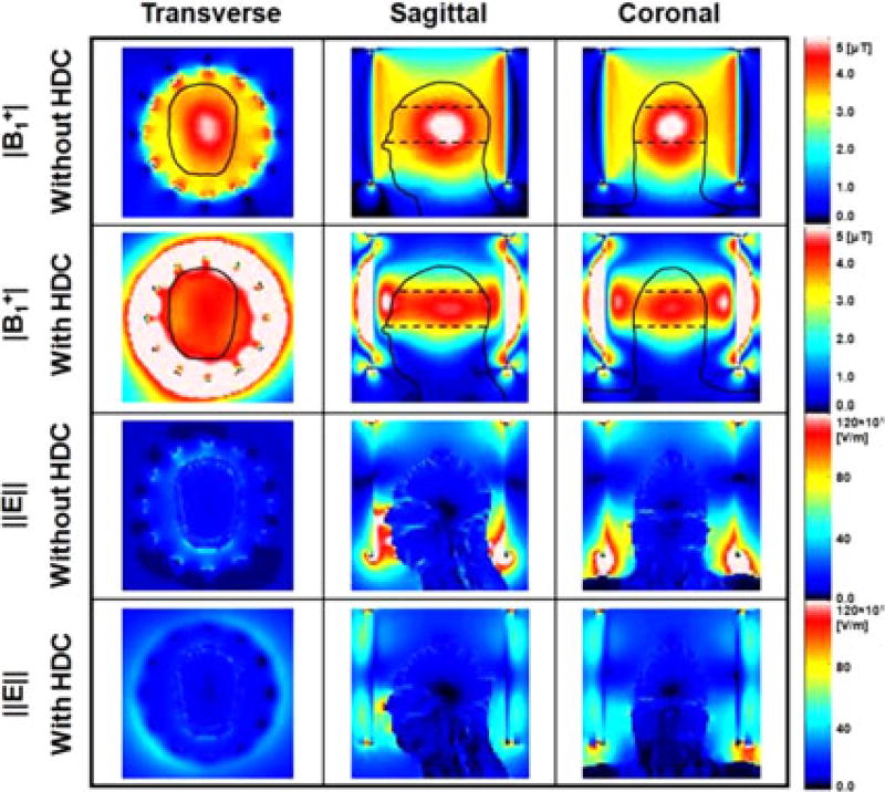
In the numerical simulations, an ROI within the head model was selected for data analysis. The ROI was centered at the isocenter of the coil, extended for 33 mm each in both z-directions and was fully contained within the head model (black dotted lines in Figs. 2 and 3).
Fig. 2.
Numerical simulation results of |B1+| (first and second row) and ‖E‖ (third and fourth row) calculated with and without a 15-mm-thick sleeve filled with HDC material of BaTiO3. The results on the central transverse (first column), sagittal (second column) and coronal (third column) slices of the head model are shown. The dashed lines in the top two rows represent the ROI used for |B1+| data analysis. Values were normalized to an average |B1+| = 4 µT at the ROI.
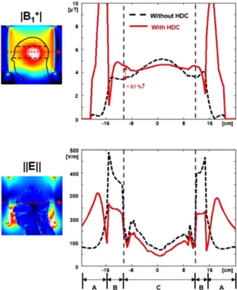
Fig. 3.
Transverse profile of (a) |B1+| and (b) electric field ‖E‖ without (black dashed line) and with (red line) a 15-mm-thick sleeve filled with HDC material of BaTiO3. The red dotted arrows in the sagittal images on the left side indicate the line selected for the graph. The specific regions noted in (b) are: (A) outside of the RF coil, (B) space between RF coil and head, and (C) inside the head. With the addition of the HDC material, there was up to 31% increase of |B1+| at the surface of the head. Values were normalized to an average |B1+| = 4 µT at the ROI.
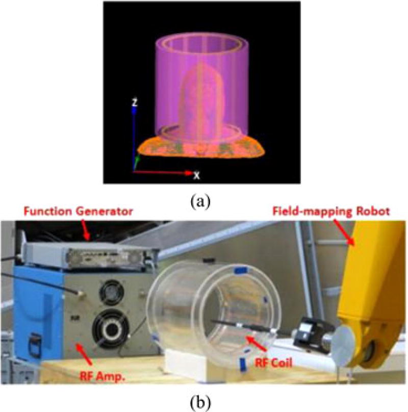
Fig. 1 shows the geometry of the RF coil, HDC material, head model, and the experimental setup. Five different geometries (inside 5 mm: ID/OD = 260/270 mm; outside 5 mm: ID/OD = 330/340 mm; outside 10 mm: ID/OD = 330/350 mm; outside 15 mm: ID/OD = 330/360 mm; outside 20 mm: ID/OD = 330/370 mm) of the HDC material with the same length along the z-direction were simulated.
Fig. 1.
(a) Geometry of the 12-rod birdcage coil (yellow) with head model and cylindrical HDC material (violet) located outside of the coil used for numerical simulations. (b) Experimental setup showing the custom-made RF head coil with the external sleeve filled with distilled water. The RF amplifier and function generator used to feed the coil at 128 MHz is visible on the left, and on the right are visible the robotic system with one of the probes used for the measurements.
2) Simulations With an Unloaded Head Coil
Additional numerical simulations with an unloaded head coil were performed to validate the results against experimental measurements.
The dimensions of the coil were same as in A.1. Two different setups were modeled: unloaded coil without HDC, and unloaded coil with an external sleeve of HDC material (ID = 330 mm, length = 300 mm, thickness = 40 mm). The HDC material used for the simulations and the related experimental measurements was distilled water (σ = 0.0048 S/m, εr = 74 at 128 MHz). A total of 12 lumped elements were used in each ring. One of the elements contained a 1-V peak-to-peak voltage source and a 50-Ω resistor, and all of the others elements included tuning capacitors such to obtained the same resonant frequency of the physical coil. The corresponding tuning capacitors values were 7 pF with the HDC material and 15 pF without it.
A cylindrical ROI was selected for data analysis with this set of numerical simulations, centered at the isocenter of the coil, 300 mm high (along z-direction) and with a diameter of 280 mm in the xy plane. The same ROI was selected for the experimental results.
EM simulations were performed using commercially available software (xFDTD, Remcom Inc., State College, PA) and data analysis was performed in Matlab (The MathWorks Inc., Natick, MA). EM simulation results with the head model (A.1) were normalized to obtain an average |B1+| = 4 µT at the ROI, whereas the EM simulations with the unloaded coil (A.2) were normalized to obtain an average transverse RF magnetic field ‖Bxy‖ = 4 µT at the ROI, to match the experimental conditions.
B. Experimental Measurements
All experiments were performed using a custom made 128-MHz birdcage head coil with the same size used in the numerical simulations (12 rungs, ID = 290 mm, L = 300 mm), an RF amplifier (ENI Inc., Richardson, TX, USA), an RF signal generator (Aeroflex Inc., Plainview, NY, USA), an electromagnetic field robotic measurement system (DASY 5NEO, with the E-field probe ER3DV6 and the H-field probe H3DV7, Schmid and Partner Engineering AG, Zurich, Switzerland). A hollow cylindrical sleeve compartment (ID/OD = 305/385 mm, L = 300 mm) filled with an HDC material made of distilled water [see Fig. 1(b)]. The designed head coil was tuned at 128 MHz and the measurement of S11 was approximately −17 dB at the frequency. The RF coil was driven in linear mode. The field-mapping robot allows measurement of the RMS value of the amplitude of the electric and magnetic field but does not provide information about the phase. Thus, it was not possible to measure the values of |B1+|; hence, all experimental results were normalized to an average ‖Bxy‖ = 4 µT in the ROI.
IV. Results
Figs. 2 and 3 show the simulation results along three selected planes (see Fig. 2) and one selected axis (see Fig. 3) of |B1+| and ‖E‖ over the human head with and without the cylindrical 15-mm-thick sleeve filled with the HDC of BaTiO3. Without HDC material, the |B1+| was high in the center of the head compared with the surface. Conversely, with the HDC material the |B1+| near the surface of the head model was increased by up to 31% (see Fig. 3), resulting in greater homogeneity of |B1+| throughout the defined ROI (black dotted lines in Figs. 2 and 3). However, this comes at a cost of lower homogeneity in the head-foot direction throughout the brain, because of the significantly decreased |B1+| and ‖E‖ near the end-ring region (see Fig. 2).
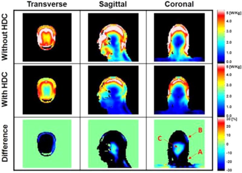
Fig. 4 shows the 10 g-avg. SAR obtained [1] with the same models. With the HDC material, the maximum 10 g-avg. SAR decreased by approximately 40% (see Fig. 4 and Table I) and the whole-head-averaged SAR decreased by approximately 26%.
Fig. 4.
Numerical simulation results of 10 g-avg. SAR obtained with and without a 15-mm-thickness cylindrical sleeve filled with the HDC material of BaTiO3. The last row shows the difference between the two cases computed as: (SARwith HDC − SARwithout HDC)/(averageSARwithout HDC) × 100%. Values were normalized to obtain an average |B1+| = 4 µT at the ROI.
TABLE I.
| Head ROI |B1+| | Head ‖E‖ | 10 g-avg. SAR | ||||
|---|---|---|---|---|---|---|
|
|
|
|
||||
| HDC Material | Mean [µT] | Std [10−6] | Mean [V/m] | Max [V/m] | Mean [W/kg] | Max [W/kg] |
| Without HDC | 4.0 | 0.49 | 168 | 12465 | 2.9 | 10 |
| BaTiO3 εr = 333, Th. = 15 mm | 4.0 | 0.43 (−12%) | 116 (−31%) | 4710 (−62%) | 1.6 (−45%) | 6 (−40%) |
| Distilled Water εr = 74, Th. = 40 mm | 4.0 | 0.44 (−10%) | 166 (−1%) | 10255 (−18%) | 2.6 (−10%) | 9 (−10%) |
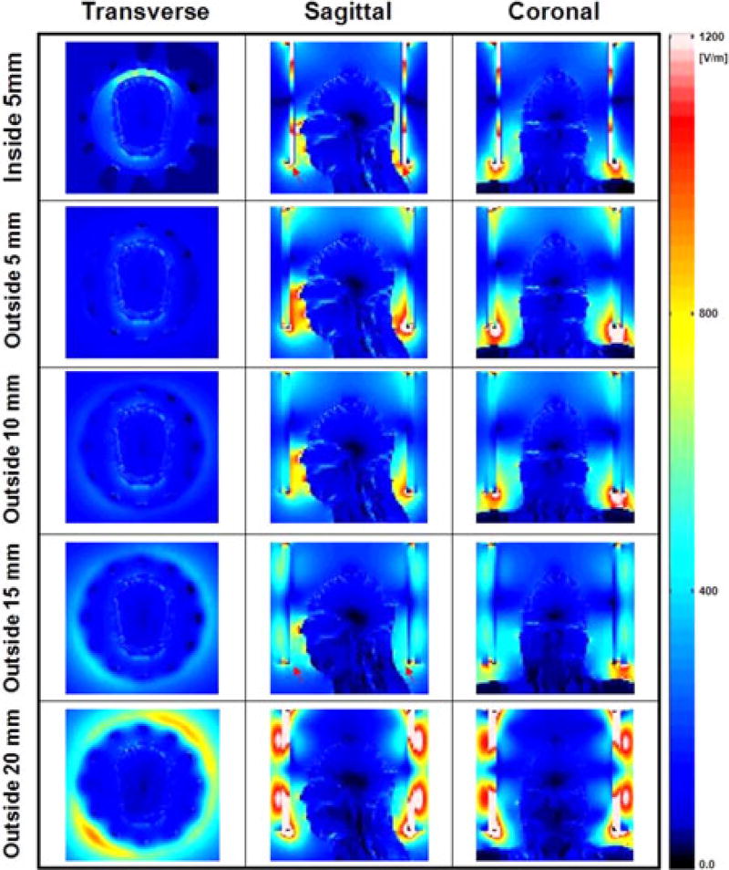
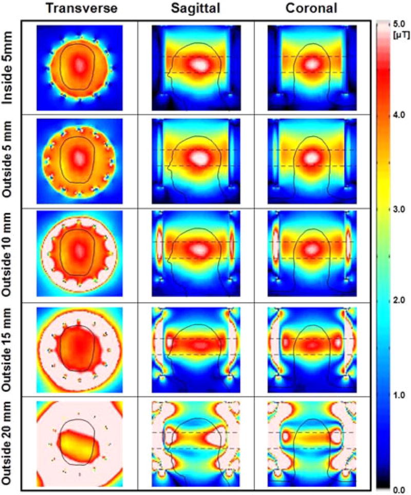
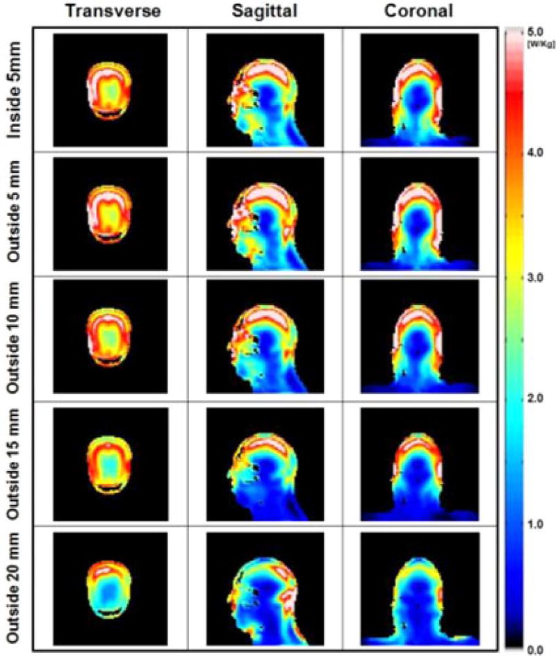
Figs. 5, 6, and 7 present the numerical simulations of ‖E‖, |B1+| and 10 g-avg. SAR, respectively, with different widths and positions of the HDC material for comparison with previous research [3], [5]. The results show that the uniformity of |B1+| within the ROI was improved up to 27% (outside 10 mm, see Table II) and the maximum 10 g-avg. SAR decreased up to 40% (outside 15 mm, see Table II) as the thickness of the material located outside of the coil increased to 15 mm, compared to a 120% increase in maximum 10 g-avg. SAR with the HDC located inside the coil.
Fig. 5.
Numerical simulation results of ‖E‖ over the entire head obtained with a sleeve of HDC material of BaTiO3 located inside the coil (first row), and outside the coil with four different thicknesses of 5, 10, 15, and 20 mm (second to fifth row). The electric field inside the head decreased up to 59% (outside 15 mm case). With further increase of the HDC material, the effect of the HDC sleeve on the electric field was reduced. Values were normalized to have average |B1+| = 4 µT at the ROI.
Fig. 6.
Numerical simulation results of |B1+| over the entire head obtained with a sleeve of HDC material of BaTiO3 located inside the coil (first row), and outside the coil with four different thicknesses of 5, 10, 15, and 20 mm (second to fifth row). The uniformity of the |B1+| within the ROI (rectangular dashed line in second and third column) was improved up to 27% (outside 10 mm). Values were normalized to have average |B1+| = 4 µT at the ROI.
Fig. 7.
Numerical simulation results of 10 g-avg. SAR over the entire head obtained with a sleeve of HDC material of BaTiO3 located inside the coil (first row), and outside the coil with four different thicknesses of 5, 10, 15, and 20mm (second to fifth row). The 10 g-avg. SAR inside the head decreased up to 40% (outside 15 mm). Values were normalized to have average |B1+| = 4 µT at the ROI.
TABLE II.
| Head ROI |B1+| | 10 g-avg. SAR | |||
|---|---|---|---|---|
|
|
|
|||
| HDC Material | Mean [µT] | Std [10−6] | Mean [W/kg] | Max [W/kg] |
| Without HDC | 4.0 | 0.49 | 2.9 | 10 |
| Inside, 5 mm | 4.0 | 0.38 (−22%) | 2.5 (−14%) | 22 (120%) |
| Outside 5 mm | 4.0 | 0.42 (−14%) | 2.5 (−14%) | 9 (−10%) |
| Outside 10 mm | 4.0 | 0.36 (−27%) | 2.1 (−28%) | 8 (−20%) |
| Outside 15 mm | 4.0 | 0.43 (−12%) | 1.6 (−45%) | 6 (−40%) |
| Outside 20 mm | 4.0 | 1.37 (180%) | 1.9 (−34%) | 9 (−10%) |
Table III shows the effect of a 15-mm-thick HDC material with an RF shield. An RF shield with ID = 380 mm, with the HDC material, generated a 9% decrease of peak 10 g-avg. SAR (i.e., 11 to 10 W/kg). The effect of the shield was higher with increasing dimensions; specifically, a shield with an ID = 440 mm generated a 33% decrease of peak 10 g-avg. SAR (i.e., 12 to 8 W/kg).
TABLE III.
| Head ROI |B1+| | 10 g-avg. SAR | |||
|---|---|---|---|---|
|
|
|
|||
| RF Shield ID [mm] | Mean [µT] | Std [10−6] | Mean [W/kg] | Max [W/kg] |
| 380 Without HDC | 4.0 | 0.53 | 3.1 | 11 |
| 380 With HDC | 4.0 | 0.49 (−8%) | 2.9 (−6%) | 10 (−9%) |
| 440 Without HDC | 4.0 | 0.49 | 3.3 | 12 |
| 440 With HDC | 4.0 | 0.42 (−14%) | 2.3 (−30%) | 8 (−33%) |
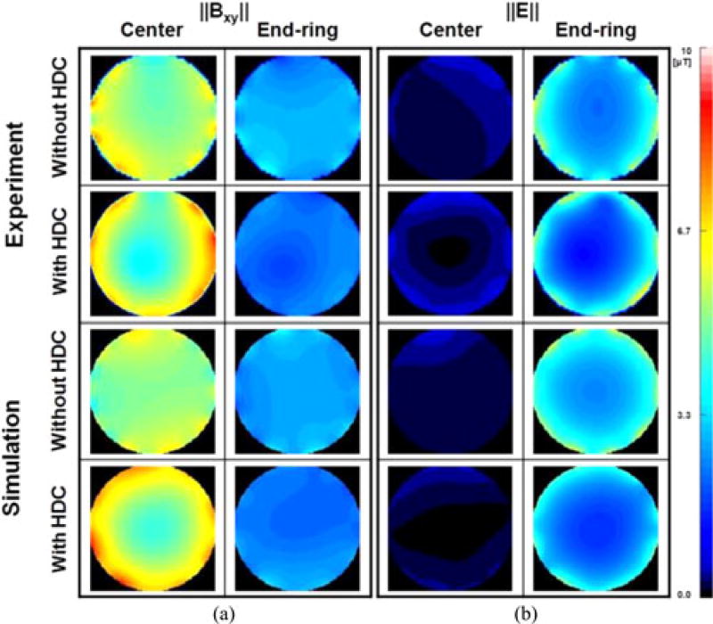
Fig. 8 shows the experimentally measured ‖E‖ and the related numerical simulation results, respectively, with and without an HDC material of distilled water. The experimental measurements showed up to 20% (425 V/m versus 339 V/m) decrease in ‖E‖ near the end-ring with a small increase near the center of the coil (i.e., 46 V/m versus 55 V/m) resulting in an overall 15% decrease (i.e., 311 V/m versus 265 V/m) of averaged ‖E‖ over the entire ROI. These results were well matched by the numerical simulations, which showed a 14% decrease near the end-ring (i.e., 457 V/m versus 394 V/m) and a 13% decrease of ‖E‖ averaged over the entire ROI.
Fig. 8.
Experimentally measured ‖Bxy‖ and ‖E‖ without (first row) and with (second row) a 40-mm sleeve filled with distilled water. Maps show the values in a transverse plane at 1 cm from the center (first and third column) and in a transverse plane near the end-rings (second and fourth column). The third and fourth row show the values calculated with the equivalent simplified numerical model. The FOV was 24 cm wide. Values were normalized to have average ‖Bxy‖ = 4 µT at the ROI of the experiments.
V. Discussion
This study extends the concept of EM field manipulation by means of placing HDC materials outside the RF coil. Compared to previous study, where HDC materials were proposed in the coil-to-sample space, this novel application presents several advantages, including: 1) It does not affect the maximum available sample size, which is limited by the ID of the RF coil, whereas in previous study [2]–[5] the size of the sample was limited by the ID of the HDC material. 2) This design allows more flexibility in optimizing the thickness and the position of the HDC material compared to a coil-to-sample design because usually much more space is available outside the RF coil rather than inside.
However, our design also has some limitations such as: 1) it may require a change of the former design of the RF coil; 2) compared to the approach using HDC material in the coil-to-sample space, a higher amount of HDC material is needed to get similar effect because of an increased ID of the material.
Foo et al. [22] proposed a method of improving RF magnetic field uniformity using an HDC material located in the “coil-to-shield” space in an RF resonator, which is similar to our approach. However, in Foo’s study, a dielectric material with suitable relative permittivity was used to increase the axial propagation constant and to decrease the radial one, resulting in reduced RF field inhomogeneity, but also in increased RF power and reduced coil sensitivity. For comparison, while our design also results in improved homogeneity, it allows for decreased whole head averaged SAR (up to 43% depending on the sleeve thickness), decreased 10 g-avg. SAR (up to 40% with a 15-mm-thick HDC), and increased |B1+| uniformity in a ROI (about 27% with a 10-mm-thick HDC) for 3 T/128 MHz head MRI.
As shown in Figs. 2–4, the ‖E‖ and the 10 g-avg. SAR with the HDC material were smaller over the whole head, and the ‖E‖ decreased between head and RF coil because of the partial shielding effect. This effect was confirmed by the experimental validation shown in Fig. 8. A similar study using a highly conductive material, i.e., copper, was shown recently [18]. The shielding effect is more obvious near the surface of the model, where high values of ‖E‖ and 10 g-avg. SAR were observed (see Figs. 2–5). Specifically, the effect of the HDC material varied within the head, depending on the specific volume considered. For example, as shown in Fig. 4 (coronal view, third row) in the area near the neck of the head model (A), close to the end-ring of the RF coil, there were high values of 10 g-avg. SAR, which were reduced with the HDC material by 40% without significant changes in |B1+|. In the surface of the model, near the temporal region (B), there was up to 31% increase of |B1+| (see also dashed rectangular region in Figs. 2 and 3) mainly due to an increased displacement current near the HDC material. This increased |B1+| generated additional induced electric field, which resulted in a 10% increase of maximum 10 g-avg. SAR [16]. Finally, in the volume in the center of the head, near the deep brain, (C), characterized by small absolute values of SAR, there was a ~10% increase in 10 g-avg. SAR. There was a 31% decrease of ‖E‖ averaged over the entire head and a 45% decrease of maximum 10 g-avg. SAR with the 15-mm-thick HDC material of BaTiO3 (see Table I).
Figs. 5 and 6 and Table II show the simulation results comparing the design proposed in previous studies (HDC inside) [3] and [5] with the design proposed herein (HDC outside the coil, with thickness ranging from 5 to 20 mm). When the HDC material was placed outside of the coil, the uniformity of |B1+| within the head ROI was improved up to 27% (outside 10 mm) (see Fig. 6 and Table II), whereas the maximum 10 g-avg. SAR decreased with increased thickness of the HDC material up to the value of 15 mm. With further increases of HDC sleeve thickness (i.e., outside 20 mm), the effect on the |B1+| uniformity and 10 g-avg. SAR was decreased (see Figs. 6 and 7 and Table II). This was probably due to an increased wavelength effect that generated additional reflections within the HDC material (see Figs. 5–7). Another significant finding was that the ‖E‖ between RF coil and the HDC material located inside the RF coil (red arrows in Fig. 5, sagittal view, first row) was much higher compared to the ‖E‖ generated when using an HDC material of 15 mm outside the coil (fourth row). The increased electric field could be significant particularly when in the presence of external devices connected to the patient (e.g., leads of physiological monitoring systems) and this may represent another possible advantage of using the HDC material outside the coil.
Table I shows numerical simulation results using distilled water (εr = 74) as HDC material. The simulations were verified experimentally with a matching setup. The choice of distilled water, rather than BaTiO3 (εr = 333), was due to the lower cost and much easier availability. Furthermore, the solid type BaTiO3 of a head coil size is not currently commercialized. The decreased shielding effect of distilled water, due to the smaller εr, was partially compensated by increasing the thickness of the material from 15 to 40 mm.
Fig. 8 shows the results of experiments and corresponding numerical simulations. The experimental results measured by a field-mapping robot showed that the ‖E‖ decreased of about 15% within the ROI and about 20% near the end-ring region, in good agreement with the corresponding numerical simulations, showing a 13% and 14% decrease, respectively. As shown in Fig. 8, there was a discrepancy between experimental and numerical results especially near the coil rungs, due to simplifications of the coil model compared to the physical coil. Such simplifications include the error margin (~10%) of the capacitor values, mechanical errors during design of the coil, as well as possible inaccuracies due to hardware system (i.e., DASY system and E/H probes, as well as RF amplifier.)
Table III includes simulation data showing how the effect of an HDC material is influenced by the presence of an RF shield. When the RF shield was located close to the 15-mm-thick HDC material, the effect of HDC materials was decreased. This is probably due to an additional electric potential due to the RF shield with opposite direction compared to the potential due to the HDC material. When the RF shield is located near the HDC material, this effect would be stronger.
The coil used in this study was a transmit coil only and the effect of the HDC material was evaluated only in terms of SAR for MR safety. Future studies may include effect of receive coil, detuning circuits, SNR evaluation, or possible effects of HDC material as a potential source of Johnson noise.
The values reported in this study are based on the specific normalization used, i.e., |B1+| = 4 µT within the ROI for simulations with a human head model. The specific value of SAR changes depends on the normalization selected: For example, if the results are normalized with |B1+| = 4 µT in the central voxel, rather than the ROI, the decrease of peak 10 g-avg. SAR for the 15-mm-thick HDC sleeve (see Table II) would then change from 40% to 26%.
The proposed method may also be suitable for higher frequencies (e.g., 298 MHz), where considerable |B1+| variation (typically 50–150% of average |B1+|) are reported. However, the specific results of this study cannot be simply extrapolated to different frequencies and further analysis should be conducted to optimize the HDC material, because of modified variable electromagnetic properties, such as increased wavelength effects resulting increased |B1+| inhomogeneity and SAR, increased conductivity and decreased relative permittivity of the HDC material.
VI. Conclusion
The study presents an evaluation of electric field and SAR in a subject undergoing MRI when an HDC material is located outside the RF coil. This method allows optimizing the electric field with respect to the thickness of the material, does not affect the space for the sample inside the coil, and has high flexibility of the HDC material optimization. The methods and results presented here can provide useful information for high field RF coil design.
Acknowledgments
This work was supported by the FDA Center of Devices and Radiological Health Critical Path Program.
Biographies

Bu S. Park received the B.S. degree (summa cum laude) in biomedical engineering from Kon-Kuk University, Seoul, South Korea, in 1996, and the Ph.D. degree in bioengineering from the Pennsylvania State University, University Park, PA, USA, in 2009.
From 1998 to 2005, he served as RF and System Engineer at Medison and Medinus Co. Ltd., South Korea. From 2009 to 2011, he completed a postdoctoral fellowship at the National Institutes of Health. Since 2011, he has been an ORISE Research Fellow at the Food and Drug Administration. His research interests include the use of computational modeling and experimental measurements aimed to design RF coils for MRI and evaluate RF safety for patients with medical implants.
Sunder S. Rajan received the Ph.D. degree in chemistry from the University of Chicago, Chicago, IL, USA, in 1984.
From 1984 to 1987, he was a Postdoctoral Fellow at the Johns Hopkins University School of Medicine, working in the field of in vivo NMR. He subsequently was an Assistant Professor at Georgetown University Hospital until 1996. During this period, he was involved in MRI research. From 1996 to 2006, he worked in the industry participating in clinical research and product development of contrast agents. He is currently a Researcher at the Center of Devices and Radiological Health, FDA, Silver Spring, MD, USA. His current research interests include MRI technology, safety aspects of MRI and MRI-based biomarkers.
Joshua W. Guag received the B.S. degree in biological resource engineering from the University of Maryland, College Park, MD, USA, in 2008, and the M.S. degree in electrical engineering from the George Washington University, Washington, DC, USA, in 2013.
He is currently a Research Engineer at the U.S. Food and Drug Administration and performs regulatory reviews and research. His research interest includes electromagnetic compatibility of medical devices.
Leonardo M. Angelone received the Laurea in electronic engineering from the University of Rome “La Sapienza,” Rome, Italy, in 2001. In 2008, he received the Ph.D. degree in biomedical engineering from Tufts University, Medford, MA, USA.
From 2001 to 2003, he completed a Research Fellowship at the Department of Radiology, Massachusetts General Hospital, Harvard Medical School. He was a Postdoctoral Consultant with the Research and Development Department, Surgical Products Division, Hologic Inc., from 2008 to 2009. Since 2009, he has been a Staff Fellow and Biomedical Engineer with the Office of Science and Engineering Laboratories, Center of Devices and Radiological Health, U.S. Food and Drug Administration, Silver Spring, MD, USA. He has authored more than 50 peer-reviewed journal articles and conference proceedings. His research interests include the assessment of energy deposition and heating induced in the human body by medical devices using electromagnetic energy.
Footnotes
Color versions of one or more of the figures in this paper are available online at http://ieeexplore.ieee.org.
Contributor Information
Bu S. Park, Division of Physics, Office of Science and Engineering Laboratories, Center for Devices and Radiological Health, Food and Drug Administration, Silver Spring, MD20993 USA
Sunder S. Rajan, Division of Physics, Office of Science and Engineering Laboratories, Center for Devices and Radiological Health, Food and Drug Administration, Silver Spring, MD20993 USA
Joshua W. Guag, Division of Physics, Office of Science and Engineering Laboratories, Center for Devices and Radiological Health, Food and Drug Administration, Silver Spring, MD20993 USA
Leonardo M. Angelone, Division of Physics, Office of Science and Engineering Laboratories, Center for Devices and Radiological Health, Food and Drug Administration, Silver Spring, MD20993 USA
References
- 1.International Standard, Medical Equipment Part 2: Particular Requirements for the Safety of Magnetic Resonance Equipment for Medical Diagnosis. IEC. 2010;601:2–33. [Google Scholar]
- 2.Yang QX, Rupprecht S, Luo W, Sica CT, Herse Z, Wang J, Cao Z, Vesek Z, Lanagan MT, Carluccio G, Ryu Y, Collins CM. Radiofrequency field enhancement with high dielectric constant (HDC) pads in a receive array coil at 3.0 T. J. Magn. Reson. Imag. 2013;38:435–440. doi: 10.1002/jmri.23988. [DOI] [PMC free article] [PubMed] [Google Scholar]
- 3.Yang QX, Wang J, Wang J, Collins CM, Wang C, Smith MB. Reducing SAR and enhancing cerebral signal-to-noise ratio with high permittivity padding at 3 T. Magn. Reson. Med. 2011;65:358–362. doi: 10.1002/mrm.22695. [DOI] [PMC free article] [PubMed] [Google Scholar]
- 4.Yang QX, Mao W, Wang J, Smith MB, Lei H, Zhang X, Ugurbil K, Chen W. Manipulation of image intensity distribution at 7.0 T: Passive RF shimming and focusing with dielectric materials. J. Magn. Reson. Imag. 2006;24:197–202. doi: 10.1002/jmri.20603. [DOI] [PubMed] [Google Scholar]
- 5.Yang QX. Method of utilization of high dielectric constant (HDC) materials for reducing SAR and enhancing SNR in MRI. US2011/0152670 A1. U.S. Patent. 2011
- 6.Neufeld A, Landsberg N, Boag A. Dielectric inserts for sensitivity and RF magnetic field enhancement in NMR volume coils. J. Magn. Reson. 2009;200:49–55. doi: 10.1016/j.jmr.2009.06.001. [DOI] [PubMed] [Google Scholar]
- 7.Luo W, Lanagan MT, Sica CT, Ryu Y, Oh SH, Ketterman M, Yang QX, Collins CM. Permittivity and performance of dielectric pads with sintered ceramic beads in MRI: Early experiments and simulations at 3 T. Magn. Reson. Med. 2013;70:269–275. doi: 10.1002/mrm.24433. [DOI] [PMC free article] [PubMed] [Google Scholar]
- 8.Snaar J, Teeuwisse WM, Versluis MJ, Buchem MV, Kan HE, Smith NB, Webb AG. Improvements in high-field localized MRS of the medial temporal lobe in humans using new deformable high-dielectric materials. NMR Biomed. 2010;24:873–879. doi: 10.1002/nbm.1638. [DOI] [PubMed] [Google Scholar]
- 9.Haines K, Smith N, Webb AG. New high dielectric constant materials for tailoring the distribution at high magnetic fields. J. Magn. Reson. 2010;203:323–327. doi: 10.1016/j.jmr.2010.01.003. [DOI] [PubMed] [Google Scholar]
- 10.Teeuwisse WM, Brink WM, Webb AG. Quantitative assessment of the effects of high-permittivity pads in 7 tesla MRI of the brain. Magn. Reson. Med. 2012;67:1285–1293. doi: 10.1002/mrm.23108. [DOI] [PubMed] [Google Scholar]
- 11.Webb AG. Dielectric materials in magnetic resonance. Concepts Magn. Res. A. 2011;38A:148–184. [Google Scholar]
- 12.Teeuwisse WM, Brink WM, Haines KN, Webb AG. Simulations of high permittivity materials for 7 T neuroimaging and evaluation of a new barium titanate-based dielectric. Magn. Reson. Med. 2012;67:912–918. doi: 10.1002/mrm.24176. [DOI] [PubMed] [Google Scholar]
- 13.Alsop DA, Connick TJ, Mizsei G. A spiral volume coil for improved RF field homogeneity at high static magnetic field strength. Magn. Reson. Med. 1998;40:49–52. doi: 10.1002/mrm.1910400107. [DOI] [PubMed] [Google Scholar]
- 14.Gabriel C, Chan TYA, Grant EH. Admittance models for open ended coaxial probes and their place in dielectric spectroscopy. Phys. Med. Biol. 1994;39(12):2183–2200. doi: 10.1088/0031-9155/39/12/004. [DOI] [PubMed] [Google Scholar]
- 15.Federal Communications Commission. Body tissue dielectric parameters. 2013 [Online]. Available: http://transition.fcc.gov/oet/rfsafety/dielectric.html.
- 16.Park BS, Webb AG, Collins CM. A method to separate conservative and magnetically-induced electric fields in calculations for MR microscopy. J. Magn. Reson. 2009;199:233–237. doi: 10.1016/j.jmr.2009.05.007. [DOI] [PMC free article] [PubMed] [Google Scholar]
- 17.Park BS, Rajan SS, Collins CM, Angelone LM. Numerical analysis of a loading effect in MRI. J. Electromagn. Anal. Appl. 2013;5:271–280. [Google Scholar]
- 18.Park BS, Neuberger T, Webb AG, Bigler DC, Collins CM. Faraday shields within a solenoidal coil to reduce sample heating: Numerical comparison of designs and experimental verification. J. Magn. Reson. 2010;202:72–77. doi: 10.1016/j.jmr.2009.09.023. [DOI] [PMC free article] [PubMed] [Google Scholar]
- 19.Collins CM, Smith MB. Signal-to-noise ratio and absorbed power as functions of main magnetic field strength, and definition of “90°” RF pulse for the head in the birdcage coil. Magn. Reson. Med. 2001;45:684–691. doi: 10.1002/mrm.1091. [DOI] [PubMed] [Google Scholar]
- 20.Collins CM, Smith MB. Spatial resolution of numerical models of man and calculated specific absorption rate using the FDTD method: A study at 64 MHz in a magnetic resonance imaging coil. J. Magn. Reson. Imag. 2003;18:383–388. doi: 10.1002/jmri.10359. [DOI] [PubMed] [Google Scholar]
- 21.Christ A, Kainz W, Hahn EG, Honegger K, Zefferer M, Neufeld E, Rascher W, Janka R, Bautz W, Chen J, Kiefer B, Schmitt P, Hollenbach HP, Shen J, Oberle M, Szczerba D, Kam A, Guag JW, Kuster N. The virtual family—Development of surface-based anatomical models of two adults and two children for dosimetric simulations. Phys. Med. Biol. 2010;55:23–38. doi: 10.1088/0031-9155/55/2/N01. [DOI] [PubMed] [Google Scholar]
- 22.Foo TKF, Hayes CE, Kang YW. Reduction of RF penetration effects in high field imaging. Magn. Reson. Med. 1992;23:287–301. doi: 10.1002/mrm.1910230209. [DOI] [PubMed] [Google Scholar]


