Abstract
The current left ventricular assist devices (LVAD) are limited by a highly invasive implantation procedure in a severely unstable group of advanced heart failure patients. Additionally, the current transcutaneous power drive line acts as a nidus for infection resulting in significant morbidity and mortality. In an effort to decrease this invasiveness and eliminate drive line complications, we have conceived a wireless miniaturized percutaneous LVAD, capable of being delivered endovascularly with a tether-free operation. The system obviates the need for a transcutaneous fluid purge line required in existing temporary devices by utilizing an incorporated magnetically coupled impeller for a complete seal. The objective of this manuscript was to demonstrate early development and proof-of-concept feasibility testing to serve as the groundwork for future formalized device development. Five early prototypes were designed and constructed to iteratively minimize the pump size and improve fluid dynamic performance. Various magnetic coupling configurations were tested. Using SolidWorks and ANSYS software for modeling and simulation, several geometric parameters were varied. HQ curves were constructed from preliminary in vitro testing to characterize the pump performance. Bench top tests showed no-slip magnetic coupling of the impeller to the driveshaft up to the current limit of the motor. The pump power requirements were tested in vitro and were within the appropriate range for powering via a wireless energy transfer system. Our results demonstrate the proof-of-concept feasibility of a novel endovascular cardiac assist device with the potential to eventually offer patients an untethered, minimally invasive support.
Keywords: Left ventricular assist device (LVAD), percutaneous, wireless energy transfer, minimally invasive
Introduction
Since the original report of first percutaneous left ventricular device, (LVAD)1, there has been a rapid rise in the use of percutaneous LVAD devices for temporary application2. Simultaneously the use of durable LVAD devices show a consistent survival benefit3. However, the invasiveness of durable LVADs in a sick population of patients is associated with adverse events that have remained constant in the last decade4. While percutaneous cardiac support devices minimize invasiveness, they are limited for short-term use, since several shortcomings hinder use for long-term applications. For example, the greatest limitation of the Impella system (Abiomed, Danvers, MA), an FDA-approved temporary percutaneous cardiac support device5–10, is related to an incompletely sealed motor, which requires a purge line to keep blood from entering the motor. Instead, we utilize a magnetically coupled system to address this limitation. The device consists of a motor and drive shaft with attached magnets completely sealed within the pump housing. An impeller surrounds the sealed drive shaft with embedded magnets that are coupled to the drive shaft magnets. Thus, as the drive shaft turns, the magnetic coupling allows the impeller to turn, without requiring a dynamic rotary seal around the drive shaft. This eliminates the need for an externally connected line of purge fluid, allowing for the potential of cardiac support outside of the hospital for short- to intermediate- term application. The combination of our pump design with a wireless energy transfer system11–13 can yield a tether-free minimally invasive percutaneously-deliverable LVAD that can significantly decrease the complications described above. This report provides a summary of early development of a novel left ventricular assist device at a percutaneously implantable scale utilizing magnetic coupling and preliminary proof-of-concept bench top testing.
Methods
Several prototypes were developed to iteratively demonstrate function at smaller sizes. We focused on several areas for optimizing pump design, including the improvement of geometrical factors. Flow simulations were utilized to analyze the effects of relative changes in design parameters. For instance, impeller blades were optimized by varying the length, width, thickness, cross-sectional profile, angle, pitch, and number of blades14. Improvements to the impeller body included variation in slope, length, diameter, and distance from the drive shaft. The pump housing was optimized by testing various outflow geometries. Additionally, several magnetic coupling arrangements were analyzed for their ability to provide adequate coupling while allowing for appropriate hydrodynamic balance and minimal friction. We also compared the performance of magnetic and hydrodynamic bearings with and without an additional axial contact bearing. We utilized rapid prototyping with 3D-printing to quickly manufacture the most promising configurations for further in vitro testing as well as computer numeric control (CNC) techniques to manufacture thin features requiring increased material strength. An overview of the five prototypes is provided in Table 1.
Table 1.
Summary of the design goals for each prototype. Five early prototypes were designed and constructed to iteratively minimize the pump size and improve fluid dynamic performance. Various geometric parameters and magnetic coupling configurations were tested.
| Prototype | Design goal |
|---|---|
| 1 | Demonstrate magnetic coupling arrangements with different impeller geometries at 3x scale including alternating vs continuous polarities, axial vs radial polarities, cylindrical vs tubular orientations, and bar vs arc segments. Prototype 1 measured 20 mm in diameter. |
| 2 | Demonstrate magnetic coupling bar magnet configuration with the proximal impeller blade configuration and the distal blade configuration at 2x scale. Prototype 2 measured 14 mm in diameter. |
| 3 | Demonstrate magnetic coupling with four radially-polarized 1 mm arc magnets at miniaturized scale. Prototype 3 measured 8 mm in diameter. |
| 4 | Improve rheological signature with re-designed axial outlet and integrated diffusor to provide increased forward flow of fluid by increasing the pressure generated. |
| 5 | Improve rheological signature with integrated diffusor combined with outlet flow straightener to provide better axial flow and inducer to properly stabilize impeller. |
Magnetic coupling
Alternating magnetic pole configurations were compared with continuous pole configurations to assess magnetic coupling strength versus balance. Axially magnetized polarities were compared to radially magnetized polarities to compare magnetic coupling strength. Cylindrical orientations were compared with tubular orientations in terms of strength and design feasibility. Bar magnets were compared with arc segments to assess coupling strength and design feasibility.
Pump design
The design range for the pump was a flow rate of 3.0 – 5.0 L/min at 100 mmHg pressure. This corresponded to rotational speeds of 20,600 and 23,600 respectively. The ventricular assist device was designed to have several fluid-contacting components. The inducer contains four blades that are immobile and attached to the inner lumen of the pump housing to reduce turbulent flow from the ventricle before reaching the impeller. The impeller contains three blades with the body attached to the driven magnetic coupling and accelerates fluid, resulting in an increase in kinetic energy. The fluid then traverses through an immobile diffuser containing three blades that is utilized to generating pressure by converting the kinetic energy from the impeller. Attached to the end of the diffuser is a flow straightener containing three blades, which orients fluid trajectories axially at the outlet of the pump.
Prototype testing
Bench top testing was utilized to test the pump operation and acquire pump performance curves. A flow loop configuration was utilized. The inlet and outlet of the pump prototype were attached to a compliance chamber via Tygon R-3603 tubing. A variable flow device was utilized to modulate flow through the loop. Two pressure sensors were utilized to measure the pressure generation of the pump by subtracting the difference between the two sensors placed at the inlet and outlet of the pump. An ultrasonic flow meter was clamped around the tubing to measure the flow rate of the pump (Transonic, Ithaca, New York, USA). The pressure sensors were each calibrated, and PowerLab (ADInstruments, Colorado Springs, CO, USA) was used as the interface to accept analog information from the sensors and convert this to digital data. LabChart (ADInstruments, Colorado Springs, CO, USA) software was used for reading and exporting the digital data. Pump performance measurements were compiled by starting with the variable flow control at its maximum position and measuring the pressure differential across the pump. The variable flow control was then progressively closed to decrease the flow and observe correspondingly increased pressure across the pump. This process was repeated until the flow was zero and the pressure generation was maximized.
Results
Prototype 1
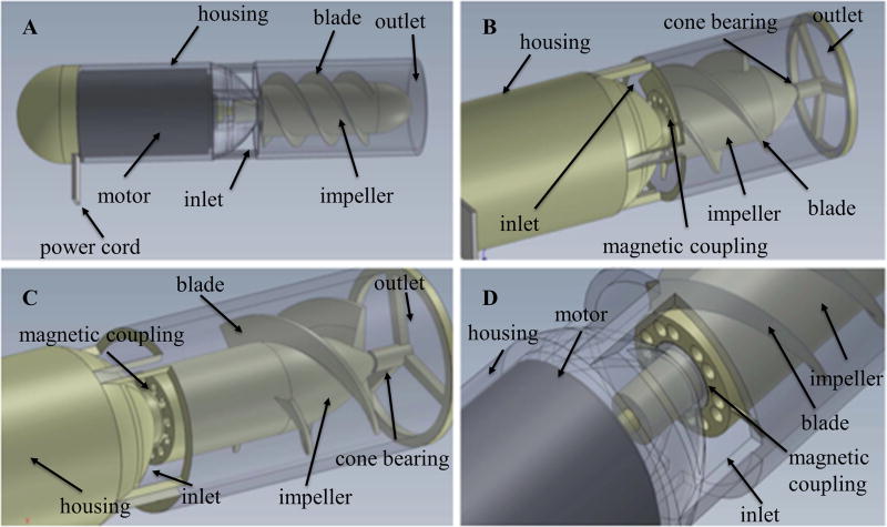
Prototype 1 was constructed to provide a functional proof of concept demonstrating successful operation of magnetic coupling. This prototype measured 20 mm and incorporated a radial outlet. Figure 1 shows the completed computer-aided design models of the first prototype, with various magnetic coupling and impeller configurations. Several magnetic arrangements were explored, including alternating vs continuous polarities, axial vs radial polarities, cylindrical vs tubular orientations, and bar vs arc segments. Bench top testing demonstrated stronger coupling for continuous polarities as compared to alternating polarities; however, as the number of continuous segments increased, this resulted in greater asymmetry of the impeller relative to the drive shaft. Tubular drive shaft magnets resulted in the highest coupling, but likewise showed the greatest asymmetry due to its magnetic pole distribution into two functional segments. Radially magnetized components showed increased coupling strength compared to axially magnetized components. Arc segments showed increased strength in comparison with bar segments, but bar segments provided greater versatility for manufacturing.
Figure 1.
Computer-aided design models of Prototype 1 with various impeller and magnetic coupling configurations: Prototype 1 measured 20 mm in diameter. Different configurations for impeller shown in (A), (B), (C), and (D) include variations in length, width, thickness, cross-sectional profile, angle, pitch, and number of blades. Different configurations for magnetic coupling include alternating vs continuous polarities, axial vs radial polarities, cylindrical vs tubular orientations, and bar vs arc segments.
Prototype 2
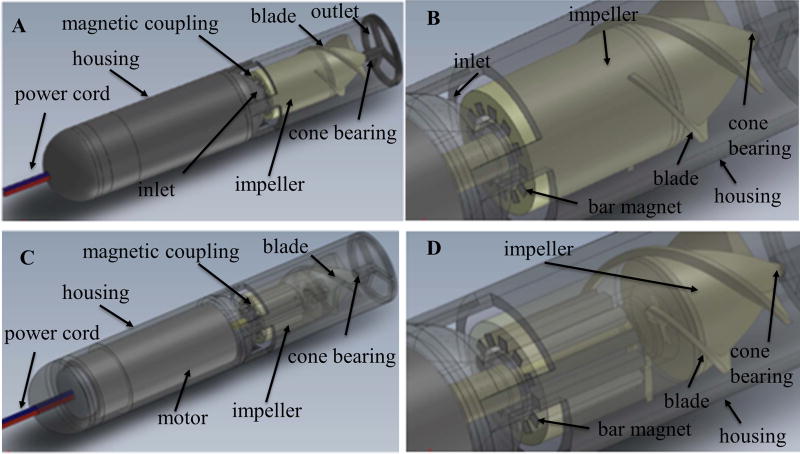
Prototype 2 measured 14 mm in diameter and was developed to test magnetic coupling of the device at a smaller pump footprint. A 12 mm brushed dc motor was used to drive the magnetic coupling system. This prototype utilized a radial outlet. The design models for the second prototype are shown in Figure 2, demonstrating an intermediately scaled version with a bar magnet configuration. The prototype demonstrated the ability of the impeller to remain coupled to the drive shaft magnets up to the current limit of the motor for both the proximal impeller blade configuration and the distal blade configuration.
Figure 2.
Computer-aided design models of Prototype 2 with a bar magnet configuration: Prototype 2 measured 14 mm in diameter. (A) and (C) are overall view of Prototype 2 with solid and transparent view respectively. (B) and (D) are detailed view of bar magnetic coupling arrangements with solid and transparent view respectively.
Prototype 3
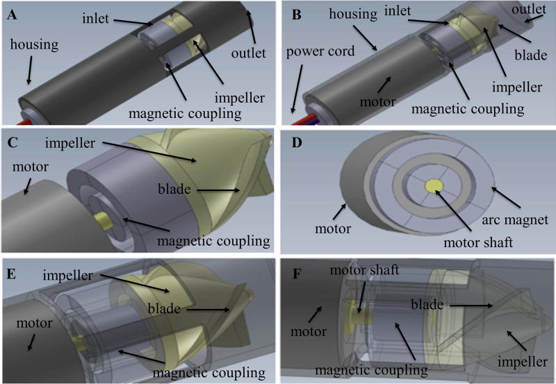
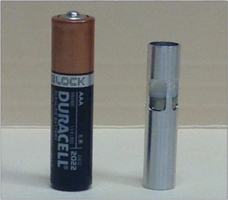
Since the femoral artery in an adult > 40 years old is approximately 8.2 mm inner diameter15, an 8 mm overall diameter version of the pump (Prototype 3) was next developed to meet this percutaneous size constraint. The design consisted of four radially-polarized 1 mm arc magnets attached to the drive shaft of the motor. A spacing of 250 um between magnets and housing components was selected to minimize dimensions and maximize coupling strength, while allowing sufficient space for free mobility of the rotating components. The computer-aided design models developed from this schematic are shown in Figure 3. Initial 3D-printed prototypes demonstrated high structural instability of the pump housing, so a CNC-machined version of the pump housing was developed, which was made from a cylindrical shell press fitted with an enclosing cap for the magnetic coupling elements. While titanium is an ideal material for a finalized product, aluminum was used for initial development due to its simplicity for manufacturing, material strength, and low cost. The CNC-machined prototype is shown in Figure 4. Bench top testing showed successful operation of the pump with adequate magnetic coupling. However, early flow loop testing demonstrated low fluid dynamic performance, so the rheological signature of the pump was optimized in subsequent prototypes.
Figure 3.
Computer-aided design models of Prototype 3 with four radially-polarized 1 mm arc magnets: Prototype 3 measured 8 mm in diameter. (A) and (B) are overall view of Prototype 2 with solid and transparent view respectively. (C) and (D) are detailed view of the magnetic coupling in different orientation. (E) and (F) are detailed view of the magnetic coupling with transparent view in different orientation.
Figure 4.
Computer numerical control (CNC)-machined version of Prototype 3 in size smaller than AAA battery. Aluminum casting was used for initial development.
Prototype 4
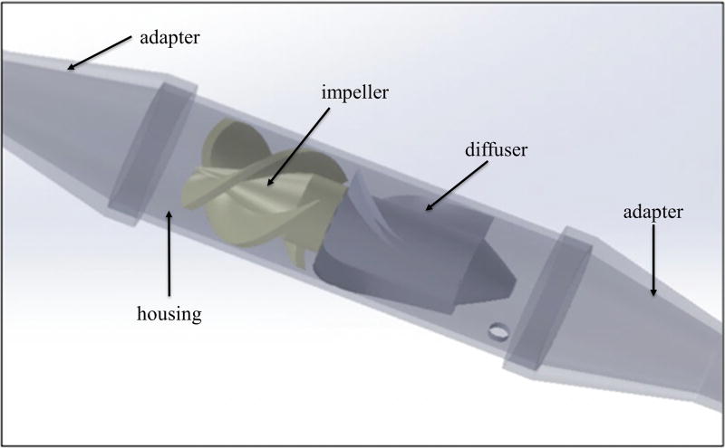
Prototype 4 was re-designed for an axial outlet, utilizing a diffuser both for improvement of the rheological signature as well as for anchoring the motor within the center of the pump. The motor utilized was 6mm in diameter, which allowed a channel for fluid movement. The diffuser provided increased forward flow of fluid and increased the pressure generation of the pump. Figure 5 shows the completed computer draft of Prototype 4, including the impeller, diffuser, pump housing, and adapters for connecting the pump to the tubing. This prototype provided a flow rate of approximately 2.4 L/min at 12,000 rpm. Further increases in pump performance were limited by reaching the maximum current threshold for the pump, which seemed to be most likely attributed to torque losses as well as friction losses due to minor manufacturing imperfections present at this stage of development.
Figure 5.
Computer-aided design draft model of Prototype 4 with a diffuser. Both ends are adapters for connecting the pump to the tubing.
Prototype 5
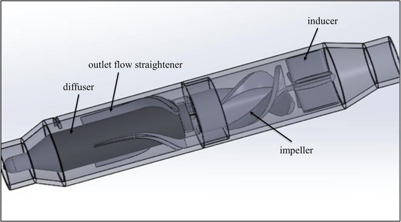
Due to current limiting of the previous version, Prototype 5 utilized a larger motor to allow for increased power for preliminary bench top testing. Figure 6 shows the completed design model for this prototype. This version included a re-designed impeller to decrease torque losses as well as to reduce stress on the leading blade edges. An inducer was included at the inlet, which served an additional purpose of stabilizing the impeller at the current stage of development where micro-scale imperfections in manufacturing could result in imbalances of the impeller. Prototype 5 included an improved diffuser and outlet flow straightener to provide exclusively axial flow. Additionally, this prototype included a tapered outlet to prevent pressure losses. The functional prototype produced a maximum flow of approximately 4 L/min at 10,000 rpm.
Figure 6.
Computer-aided design model of Prototype 5 optimized from Prototype 4 by including a larger motor to allow for increased power consumption, a re-designed impeller to decrease torque losses as well as to reduce stress on the leading blade edges, a re-designed diffuser with outlet flow straightener incorporated to provide better axial flow, a inducer to compensate possible imbalances caused by micro-scale imperfections in manufacturing, and a tapered outlet to prevent pressure losses.
Power testing
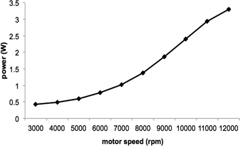
The 6 mm motor’s power profile was investigated for Prototype 4. The motor speed was varied from 3,000 rpm to 12,000 rpm in increments of 1,000 rpm. The current limit of the motor was reached at a speed of 11,000 rpm, corresponding to a power consumption of 2.94 W for a flow rate of 2.3 L/min. The next increment at 12,000 rpm resulted in a maximum power consumption of 3.3 W for a flow rate of 2.4 L/min, though the pump’s speed was quickly diminished as the current limit was exceeded. As expected of the pump affinity equation for power (P2/P1=[N2/N1]^3), the relationship between increasing motor speed and power consumption followed an exponential relationship, as depicted in Figure 7. The current limit is shown after 11,000 rpm as the drop-off from the exponential curve after this point.
Figure 7.
Power consumption as a function of motor speed for Prototype 4. The exponential relationship between increasing motor speed and power consumption accords well with the pump affinity equation.
Pump performance testing
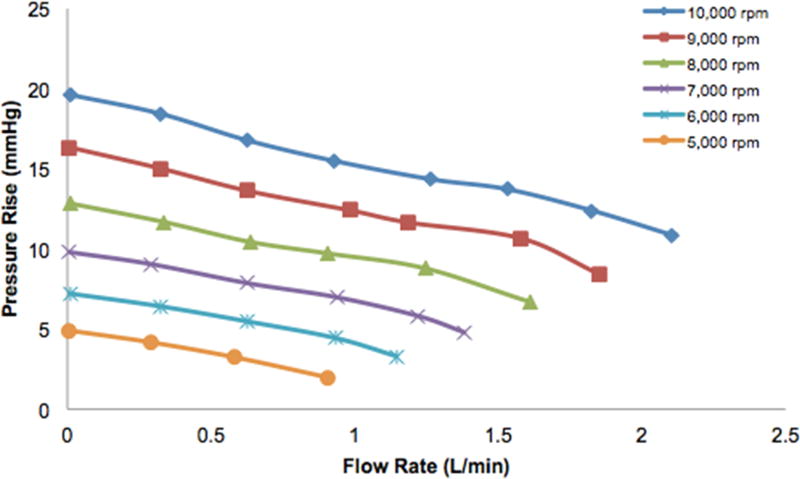
Pump performance curves were acquired for Prototype 4 and Prototype 5. We performed preliminary flow loop testing at lower speeds of 5,000 rpm to 10,000 rpm for Prototype 4, due to current limiting of the motor resulting from friction losses. Pressure rise versus flow rate curves are demonstrated in Figure 8 for pump speeds of 5,000 rpm, 6,000 rpm, 7,000 rpm, 8,000 rpm, 9,000 rpm, and 10,000 rpm. At a pump speed of 10,000 rpm, the maximum flow rate was 2.1 L/min and the shut-off pressure was 20 mmHg. The increasing speed curves show close adherence to the affinity law relationship for pressure (H2/H1=[N2/N1]^2) and flow rate (Q2/Q1=[N2/N1]), as is seen by comparing the respective curves for 5,000 rpm and 10,000 rpm. Extrapolating these curves to the optimum pump speeds used in the simulations, this corresponds to a flow rate of ~3.6 L/min for 100 mmHg at 26,600 rpm and a flow rate of ~1.0 L/min for 100 mmHg at 23,600 rpm.
Figure 8.
Preliminary bench top pump performance curves for Prototype 4 at lower speeds of 5000 to 10000 rpm. Relationship between pressure and flow closely adheres to the affinity law, showing that a flow rate of ~3.6 L/min for 100 mmHg at a pump speed of 26,600 rpm and a flow rate of ~1.0 L/min for 100 mmHg at a pump speed of 23,600 rpm can be reached when the curve is extrapolated to the optimum pump speed.
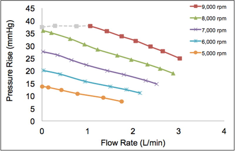
Similarly, the analogous preliminary flow loop testing was carried out for Prototype 5, using the lower speeds of 5,000 rpm to 9,000 rpm. The corresponding curves are shown in Figure 9, illustrating the relationship between flow rate and pressure rise for the various pump speeds. The maximum flow rate at 9,000 rpm was 3.0 L/min. The shut-off pressure condition at this speed resulted in current limitation of the motor, so the recorded value was 37 mmHg instead of the expected value of approximately 45 mmHg from the curve (grey dashed line). Once again, there was close adherence to the affinity law relations for pressure and flow rate. Extrapolating these curves to the simulation pump speeds result in a flow rate of ~5.7 L/min for 100 mmHg at a pump speed of 23,600 rpm and a flow rate of ~3.2 L/min for 100 mmHg at a pump speed of 20,300 rpm.
Figure 9.
Preliminary bench top pump performance curves for Prototype 5 at lower speeds of 5000 to 9000 rpm. Relationship between pressure and flow closely adheres to the affinity law, showing that a flow rate of ~5.7 L/min for 100 mmHg at a pump speed of 23,600 rpm and a flow rate of ~3.2 L/min for 100 mmHg at a pump speed of 20,300 rpm can be reached when the curve is extrapolated to the optimum pump speed.
Discussion
The clinical implementation of a wireless percutaneous left ventricular assist device could drastically improve clinical outcomes of advanced heart failure patients by eliminating procedural complications of the current implantation procedure, significantly diminishing recovery time, and eliminating the risk for driveline infection. We have designed and developed several early prototypes of a miniaturized magnetically coupled left ventricular assist device that does not rely on a transcutaneous purge line, which could ultimately allow for a fully wireless and tether-free minimally invasive solution. Our goal was to demonstrate proof-of-concept and early feasibility, investigating optimum design features as initial steps towards formalized device development.
Five physical prototypes were constructed. Prototype 1 was a plastic 3D-printed 20 mm diameter model and proved the concept of magnetic coupling at a larger dimensional scale. Prototype 2 was scaled down to 14 mm and demonstrated successful magnetic coupling of the drive shaft and impeller at an intermediate size. Prototype 3 utilized CNC machining techniques to validate the ability to produce a functional prototype at the percutaneous scale. Prototype 4 improved the fluid performance by integrating a diffuser with an axial outlet. Prototype 5 consisted of a flow straightener, an improved impeller, a higher power motor, and resulted in further improvement of the fluid performance of the pump.
Flow loop testing for Prototype 4 at the lower speed range showed a maximum flow rate of 2.1 L/min at 10,000 rpm and a shut-off pressure of 20 mmHg, which correspond to a flow rate of 3.6 L/min at 100 mmHg for a speed of 26,600 rpm. Analogous testing for Prototype 5 along the lower speed range demonstrated a maximum flow rate of 3.0 L/min and a shut-off pressure of ~40 mmHg, corresponding to a flow rate of 5.7 L/min at 100 mmHg for a pump speed of 23,600 rpm. Both sets of curves showed high adherence to the pump affinity relationships.
There are several optimizations that can be made to further improve the performance of the pump. One of the key factors diminishing the efficiency of the pump is friction loss attributed to the rotating components. These specific areas include the drive shaft magnets against the inner lumen of the enclosing cap, the impeller magnets against the outer lumen of the enclosing cap and inner lumen of the pump housing, and the impeller surface against the inner lumen of the pump housing. In an ideal manufacturing environment, perfect alignment of the driving magnets onto the motor as well as the driven magnets onto the impeller should allow full alignment of the drive shaft and impeller, resulting in complete balance and suspension of the magnetic coupling units without any contact with the magnetic coupling cap or the pump housing. At the current stage of manufacturing, manual assembly of these magnetic components results in sub-millimeter imperfections that disrupt optimal alignment. Implementing a more precise manufacturing technique for assembling the magnets would be the definitive solution for this issue. In the meantime, the use of low-friction materials or coatings for the magnetic coupling cap and inner lumen of the pump housing, such as polytetrafluoroethylene, can serve as a temporary short-term solution to decrease friction losses.
Additionally, improving the impeller can substantially increase the efficiency of the driving motor. The majority of miniature brushless dc motors show optimal efficiency at higher speeds greater than ~20,000 rpm. While a large cross-sectional area of impeller blade contact with the propelled fluid maximizes the flow, it increases the torque required for the motor and thus results in limitations to lower speeds below the range of optimum efficiency. Therefore, the efficiency can be greatly improved by decreasing the torque of the impeller blade against the fluid until an optimal balance is reached closer to the maximum efficiency speed of the motor. Also, if future flow trajectory simulations of the area between the impeller magnets and drive cap demonstrate stasis, a fluid washout channel can be implemented into the impeller design by making an extruded narrow cylindrical cut along the axial dimension of the impeller.
In summary, we have designed, developed, and tested a functioning proof-of-concept prototype of a miniaturized percutaneous left ventricular assist device capable of wireless power operation. Future technical optimizations in pump performance will allow for in vivo testing, with the ultimate goal of eventually providing advanced heart failure patients with a minimally invasive tether-free solution.
Acknowledgments
The project described was supported by the National Heart, Lung, and Blood Institute of the National Institutes of Health under Award Number T3511L007649 and by the National Center for Advancing Translational Sciences of the National Institutes of Health under Award Number TL1TR000141. The content is solely the responsibility of the authors and does not necessarily represent the official views of the National Institutes of Health.
References
- 1.Merhige ME, Smalling RW, Cassidy D, et al. Effect of the hemopump left ventricular assist device on regional myocardial perfusion and function. Reduction of ischemia during coronary occlusion. Circulation. 1989;80:III158–66. [PubMed] [Google Scholar]
- 2.Stretch R, Sauer CM, Yuh DD, Bonde P. National trends in the utilization of short-term mechanical circulatory support: incidence, outcomes, and cost analysis. J Am Coll Cardiol. 2014;64:1407–1415. doi: 10.1016/j.jacc.2014.07.958. [DOI] [PubMed] [Google Scholar]
- 3.Kirklin JK, Naftel DC, Pagani FD, et al. Sixth INTERMACS annual report: a 10,000-patient database. J Heart Lung Transplant. 2014;33:555–564. doi: 10.1016/j.healun.2014.04.010. [DOI] [PubMed] [Google Scholar]
- 4.Bonde P, Dew MA, Meyer D, et al. 4 National trends in readmission (REA) rates following left ventricular assist device (LVAD) therapy. The Journal of Heart and Lung Transplantation. 2011;30:S9. [Google Scholar]
- 5.Meraj P, Maini B, Mascari P, Jauhar R. TCT-131 Survival Benefit when using Impella 2.5 Percutaneous LVAD prior to PCI of Unprotected Left Main Culprit Vessel in Patients with Acute Myocardial Infarction Complicated by Cardiogenic Shock. J Am Coll Cardiol. 2016;68:B53. [Google Scholar]
- 6.Tuseth V, Salem M, Pettersen R, et al. Percutaneous left ventricular assist in ischemic cardiac arrest. Crit Care Med. 2009;37:1365–1372. doi: 10.1097/CCM.0b013e31819c0642. [DOI] [PubMed] [Google Scholar]
- 7.Vase H, Christensen S, Christiansen A, et al. The Impella CP device for acute mechanical circulatory support in refractory cardiac arrest. Resuscitation. 2017;112:70–74. doi: 10.1016/j.resuscitation.2016.10.003. [DOI] [PubMed] [Google Scholar]
- 8.Ouweneel DM, Eriksen E, Sjauw KD, et al. Percutaneous Mechanical Circulatory Support Versus Intra-Aortic Balloon Pump in Cardiogenic Shock After Acute Myocardial Infarction. J Am Coll Cardiol. 2017;69:278–287. doi: 10.1016/j.jacc.2016.10.022. [DOI] [PubMed] [Google Scholar]
- 9.Flaherty MP, Pant S, Patel SV, et al. Hemodynamic Support with a Micro-Axial Percutaneous Left Ventricular Assist Device (Impella®) Protects Against Acute Kidney Injury in Patients Undergoing High-Risk Percutaneous Coronary Intervention. Circ Res. 2017 doi: 10.1161/CIRCRESAHA.117.311107. CIRCRESAHA.116.309738. [DOI] [PubMed] [Google Scholar]
- 10.Schibilsky D, Kruger T, Lausberg HF, et al. Impella 5.0 as a Second-Line Mechanical Circulatory Support Strategy After Extracorporeal Life Support. Artif Organs. 2016;40:909–916. doi: 10.1111/aor.12804. [DOI] [PubMed] [Google Scholar]
- 11.Wang JX, Smith JR, Bonde P. Energy transmission and power sources for mechanical circulatory support devices to achieve total implantability. Ann Thorac Surg. 2014;97:1467–1474. doi: 10.1016/j.athoracsur.2013.10.107. [DOI] [PubMed] [Google Scholar]
- 12.Waters BH, Smith JR, Bonde P. Innovative Free-range Resonant Electrical Energy Delivery system (FREE-D System) for a ventricular assist device using wireless power. ASAIO J. 2014;60:31–37. doi: 10.1097/MAT.0000000000000029. [DOI] [PubMed] [Google Scholar]
- 13.Waters B, Sample A, Smith J, Bonde P. Toward total implantability using free-range resonant electrical energy delivery system: achieving untethered ventricular assist device operation over large distances. Cardiol Clin. 2011;29:609–625. doi: 10.1016/j.ccl.2011.08.002. [DOI] [PubMed] [Google Scholar]
- 14.Stepanoff AJ. Centrifugal and Axial Flow Pumps, (1957) 2002. Chap. [Google Scholar]
- 15.Sandgren T, Sonesson B, Ahlgren R, Länne T. The diameter of the common femoral artery in healthy human: influence of sex, age, and body size. J Vasc Surg. 1999;29:503–510. doi: 10.1016/s0741-5214(99)70279-x. [DOI] [PubMed] [Google Scholar]


