

Abstract
In vivo tissue responses and functional efficacy of electrospun membranes based on polyurethane (PU) and gelatin (GE) as biomimetic coatings for implantable glucose biosensors was investigated in a rat subcutaneous implantation model. Three electrospun membranes with optimized fiber diameters, pore sizes, and permeability, both single PU and coaxial PU‐GE fibers and a solvent cast PU film were implanted in rats to evaluate tissue responses. For functional efficacy testing, four sensor variants coated with the above mentioned electrospun membranes as mass‐transport limiting and outermost biomimetic coatings were implanted in rats. The electrospun PU membranes had micron sized pores that were not permeable to host cells when implanted in the body. However, PU‐GE coaxial fiber membranes, having similar sized pores, were infiltrated with fibroblasts that deposited collagen in the membrane's pores. Such tissue response prevented the formation of dense fibrous capsule around the sensor coated with the PU‐GE coaxial fiber membranes, which helped improve the in vivo sensitivity for at least 3 weeks compared to the traditional sensors in rat subcutaneous tissue. Furthermore, the better in vitro sensor's sensitivity due to electrospun PU as the mass‐transport limiting membrane translated to better in vivo sensitivity. Thus, this study showed that electrospun membranes can play an important role in realizing long in vivo sensing lifetime of implantable glucose biosensors. © 2017 The Authors Journal of Biomedical Materials Research Part A Published by Wiley Periodicals, Inc. J Biomed Mater Res Part A: 106A: 1072–1081, 2018.
Keywords: continuous glucose monitoring, electrospun coaxial fiber membranes, implantable electrochemical sensor, in vivo functional efficacy, tissue reactions
INTRODUCTION
Dynamic foreign body reactions on the sensor surface have been the crucial barrier for the design of reliable, long‐term implantable glucose biosensors.1, 2, 3, 4, 5 Specifically, biofouling, inflammation, fibrosis, receding microvasculature, and extracellular release of lysosomal contents are responsible for the unpredictable negative drift in sensor signal.1 However, from a practical perspective, three main aspects affect the implanted glucose biosensor function: (1) robustness of sensor design, (2) biofouling by proteins and cells, and (3) fluctuation of interstitial fluid levels at implant site.1
Electrochemical glucose biosensors are known to lose sensitivity as soon as they are implanted followed by a downward drift until failure. From the sensor design perspective, Valdes and Moussy showed that the activity of the immobilized glucose oxidase (GOD) enzyme is a fundamental limiting factor in vivo, as it deteriorates due to accumulation of H2O2 in the sensor element.6 Moussy et al. developed a sensor design with a coil reinforced with cotton that allows loading of excess enzyme as working electrode to cope with the demands for long‐term implantation.7, 8, 9, 10, 11, 12 This sensor design provides sensitivities >40 nA/mM,10 which are much better compared to sensors tested earlier, because current measurements in pA/mM are susceptible to large fluctuations in vivo.5, 13, 14
Biofouling significantly lowers the sensitivity of implanted sensors and its effect at least initially can be minimized by tailoring surface chemistry of the sensors.1, 2, 3, 4, 15 However, it cannot stop the eventual adhesion and spreading of macrophages and foreign body giant cells on sensor surface that significantly reduce the quantity of glucose reaching the sensor.5
The tissue microenvironment inherently has much lower (interstitial) fluid levels compared to in vitro testing in simulated body (100%) fluids.16, 17, 18 Further, the interstitial fluid levels at the implant site vary significantly depending on the stage of inflammation and mechanical disturbances.1, 2, 3, 4 Helton et al. also reiterate the role of mechanical (compressive, tensile, shear and contractile) forces and micromotion (due to breathing, and pulsing blood vessels), which chronically disrupt the tissue stabilization during the natural wound healing process causing unpredictable fluctuations in interstitial fluid levels resulting in erratic sensor signals.1
Biomaterial coatings can provide the required chemical, structural and mechanical buffer zone for fulfilling the ultimate goal of long‐term implantable glucose biosensors.5, 14, 19, 20, 21 Earlier, we reported electrospun membranes based on polyurethane (PU) and gelatin (GE) both in single polymer and coaxial dual polymer formats to coat miniature glucose biosensors, and systematically characterized their physical, chemical and mechanical properties, as well as their effect on sensor sensitivity.10, 11, 12 The fibroporous membranes, due to their high pore volume, helped us achieve significantly higher preimplantation sensor sensitivity compared to the traditional solvent‐cast epoxy‐PU (EPU) membranes.10, 12 Here, we investigate if the higher in vitro sensitivity translates to that in vivo. Furthermore, Sanders et al. showed that fiber diameters of 1 to 5.9 μm prevent fibrous capsule formation around electrospun membranes.22 Hence, we envisaged biomimetic 6PU10GE coaxial fiber membranes would prevent not only the fibrous capsule formation, but also the barrier cell layer formation at the sensor–tissue interface.
Current study evaluated the tissue responses to four implant variants: three electrospun membranes namely, 8PU, 12PU, and 6PU10GE (wherein the number prefix indicates the concentration [wt %] of the polymer solution used to electrospin), and one solvent cast nonporous PU‐film (control). The in vivo functional efficacy of electrospun membranes in mass transport limiting (8PU) and tissue engineering (12PU and 6PU10GE) roles on the surface of implantable glucose biosensors was also assessed. Significant findings were that better in vitro sensitivity of sensors having electrospun membrane for mass transport‐limiting translated to better in vivo sensitivity, and the biomimetic 6PU10GE coatings prevented fibrous capsule formation on sensor surface, thus improving sensor sensitivity for at least 3 weeks.
MATERIALS AND METHODS
Thermoplastic PU (Selectophore™), GE from porcine skin (type A), tetrahydrofuran (THF), N,N‐dimethylformamide (DMF), bovine serum albumin (BSA), glutaraldehyde (GA) grade I, 50% and grade II, 25%, GOD (EC 1.1.3.4, Type X‐S, Aspergillus niger, 157 500 U/g; Sigma), ATACS 5104/4013 epoxy adhesive, Brij 30, D‐(+)‐glucose, hydrochloric acid, nitric acid, ammonium hydroxide, neutral buffered formalin (4%), Mayer's hematoxylin, Eosin Y, Masson's Trichrome kit, xylene, and 0.01 M phosphate buffered saline (PBS) pH 7.4 tablets were purchased from Sigma‐Aldrich (UK). Glacial acetic acid, absolute ethanol, 2,2,2‐trifluoroethanol (TFE), and basic histology consumables were purchased from Fisher (UK). Teflon‐coated platinum–iridium (Pt/Ir) (9:1 in weight, Ø 0.125 mm) and silver wires (Ø 0.125 mm) were obtained from World Precision Instruments (Sarasota, FL). Sprague Dawley rats (Harlan UK, Oxon, UK) weighing between 175 and 200 g were housed in the experimental animal facility at Brunel University. All animal procedures had ethical approval from the ‘Animal Welfare Ethical Review Board’ of Brunel University and covered under the appropriate project (PPL No. 70–6993) and personal (PIL No. 70–21528) licenses from Home Office, UK. Home office, UK guidelines for the care and use of laboratory animals (Animals [Scientific Procedures] Act 1986) were observed. Isofluorane (ISOFlo®), ketamine hydrochloride (Ketaset), xylazine (Chanazine), buprenorphine hydrochloride (Vetergesic), soft paraffin (Lacri‐lube), atipamezole hydrochloride (ATIPAM), sodium pentobarbitone (Euthatal), and carprofen (RIMADYL) were supplied by Lab Services (London, UK). Ethicon™ 5–0 Polygalactin and Prolene (Johnson & Johnson) sutures were purchased from Vet Tech Solutions (Cheshire, UK). Surgical consumables were purchased from Barrier Healthcare (Lincolnshire, UK). ALPHELYS RCL‐2 formalin‐free fixative was purchased from Mitogen (UK). Abbott FreeStyle Lite blood glucose meter and test strips were purchased from Point Pharmacy (UK). Medical oxygen cylinders were supplied by Air Liquide UK. Deionized water purified using a Barnstead water purification system was used for all experiments.
Electrospinning single and coaxial fiber membranes
The methods for traditional and coaxial electrospinning of PU and PU‐GE (coaxial) fiber membranes both on static plate collector and directly on the miniature sensor surface using a dynamic collector were presented in our earlier reports.10, 11, 12 The materials and parameters for electrospinning are summarized in Table 1.
Table 1.
Test Implant Variants and the Electrospinning Parameters for Spinning the Respective Membranes or Sensor Coatings10, 12
| Test Implant Designation | Electrospinning Parametersa | ||
|---|---|---|---|
| Collector; Flat‐Tip Spinneret | Solution Parameters | Physical Parameters (Voltage; Flow Rate; Distance) | |
| Biocompatibility testing (1 × 1 cm2 sheets) | |||
| PU film | n/a | n/a | n/a |
| 8PU | Static; 22G needle | 8% PU in 40:60 w/w THF:DMF | 21 kV; 0.6 mL/h; 22 cm |
| 12PU | Static; 22G needle | 12% PU in 50:50 w/w THF:DMF | 20 kV; 1.2 mL/h; 22 cm |
| 6PU10GE | Static; ∼21G core/∼10G shell coaxial needle | 6% PU in TFE (core) and 10% GE in TFE (shell) | 13.25 kV; 0.8 mL/h (core) and 1.2 mL/h shell; 15 cm |
| In vivo functional efficacy testing of implantable continuous glucose monitoring sensors | |||
| Pt‐GOD‐EPU | n/a | n/a | n/a |
| Pt‐GOD‐8PU‐12PU | Dynamic; 22G needle | 8% PU in 40:60 w/w THF:DMF followed by 12% PU in 50:50 w/w THF:DMF | 21 kV; 0.6 mL/h; 22 cm followed by 20 kV; 1.2 mL/h; 22 cm |
| Pt‐GOD‐EPU‐12PU | Dynamic; 22G needle | 8% PU in 50:50 w/w THF:DMF | 20 kV; 1.2 mL/h; 22 cm |
| Pt‐GOD‐EPU‐6PU10GE | Dynamic; ∼21G core/∼10G shell coaxial needle | 6% PU in TFE (core) and 10% GE in TFE (shell) | 13.25 kV; 0.8 mL/h (core) and 1.2 mL/h shell; 15 cm |
Ambient temperature and humidity for all electrospinning was 20 ± 2°C and 40 ± 5%, respectively.
Sensor preparation and designations
The method for sensor manufacture was described in our previous reports, except that the Pt‐Ir working electrode coil in this study had an additional interference reducing layer.10, 23 The bare cotton‐reinforced Pt‐Ir coil was coated with a polyphenylenediamine layer by electropolymerization at 0.7V versus standard calomel electrode in a PBS containing 5 mM phenylenediamine, 20 U/mL GOD, and 1 μL/mL 0.25% GA.7, 10, 23 Figure 1 shows the schematic representation of the sensor design and function as well as the scanning electron microscopy (SEM) images showing the cross‐section of the sensors tested in this study. The typical working electrode had a cotton reinforced Pt/Ir coil (designated as Pt) coated with GOD immobilized on BSA using GA crosslinking. The base Pt‐GOD sensors were coated with either EPU or electrospun 8PU membranes. The respective sensors were designated as Pt‐GOD‐EPU and Pt‐GOD‐8PU. To test the efficacy of electrospun membranes as tissue engineering sensor surface coatings, two membrane configurations, namely, 12PU and 6PU10GE were used. The four sensor configurations tested for in vivo functional efficacy were Pt‐GOD‐EPU, Pt‐GOD‐8PU‐12PU, Pt‐GOD‐EPU‐12PU, and Pt‐GOD‐EPU‐6PU10GE (Table 1).
Figure 1.
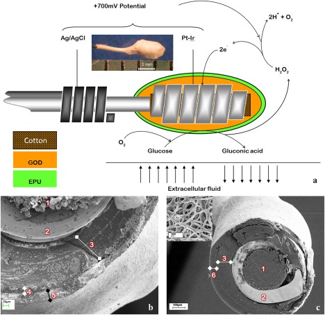
The design of the amperometric sensor used in this study. (a) A schematic representation of the sensor design and function; inset—light microscopy photo to illustrate the size of the working electrode, (b, c) scanning electron microscopy images showing the cross‐section of the sensors, wherein 1 is cotton, 2 is Pt‐Ir coil, 3 is GOD immobilized on BSA using GA crosslinking, 4 is EPU mass transport limiting membrane, 5 is electrospun membrane as tissue engineering coating, and 6 is electrospun membrane as mass transport limiting membrane, (c) inset—SEM image showing surface porosity of electrospun coating on sensor.
Crosslinking of GE
The GE in the 6PU10GE coaxial fibers of the electrospun sheets or coatings on sensors was stabilized by GA crosslinking in a GA vapor environment in a vacuum desiccator with the desiccant replaced by 10 mL of 25% aqueous GA solution for three days.
Sensor calibration and testing
Preimplantation sensitivity of the test sensors was measured using Apollo 4000 Analyser (World Precision Instruments, Sarasota, FL).10 Sensors were equilibrated in PBS at an applied voltage of 0.7V between the Pt‐Ir working electrode and the Ag/AgCl reference electrode, while continuously stirring the PBS solution. Calibration plots for the sensors were obtained by measuring current while increasing the glucose concentration (0–30 mM). The sensitivity (S) of each sensor was calculated using the equation:
where I 15 and I 5 mM are the steady state currents for 15 and 5 mM glucose concentration, respectively.
Tissue response evaluation
The tissue responses to the test membranes (1 × 1.5 cm2 sheets) were evaluated using male Sprague Dawley rats acclimatized to local environment for 1 week prior to surgery. The rats were anaesthetized with ketamine (80 mg/kg) and xylazine (10 mg/kg) and eyes lubricated with Lacri‐lube. Subcutaneous injections of 0.05 mg/kg buprenorphine hydrochloride and 10 mg/kg carprofen were used as analgesics. The dorsal skin was shaved and disinfected with iodine. Along the dorsal midline, three 1.5 cm longitudinal incisions were made, about 3 cm apart. At each incision, two lateral subcutaneous pockets were made. In each pocket one test membrane was inserted at the subcutaneous level about 1 cm away from the incision. Prior to implantation, the different scaffolds were sterilized by their incubation in 70% ethanol for 1 h followed by washing in several changes of sterile saline. The incisions were closed using a degradable Ethicon™ 5–0 Polygalactin. Following implantation, atipamezole hydrochloride was administered for reversal of the sedative effects of xylazine. The rats were given standard pellet diet and fresh water. The implant sites were physically observed at regular intervals. A total of six rats were divided into two groups of three each. Four implant variables: PU film, 8PU, 12PU, 6PU10GE were assessed in this study. Per time point, three samples of each implant variable were implanted. The two groups of rats were sacrificed after 4 and 9 weeks, respectively, and subsequently the implant sites were harvested and fixed in RCL‐2 formalin free fixative.
Histology
RCL‐2 fixed tissues were dehydrated through graded ethyl alcohol solutions (70, 95, and 100%), cleared with xylene and embedded in paraffin. Seven‐micrometer thick paraffin sections were stained with hematoxylin and eosin (H&E), and Masson's trichrome (MT). The stained sections were observed under light microscope and digital images were captured using SP‐500 POL microscope equipped with Minicam DCM 1.3M USB 2.0 digital camera (Brunel Microscopes, Bristol, UK).
Subcutaneous implantation of glucose sensors
Sensor configurations Pt‐GOD‐8PU‐12PU, Pt‐GOD‐EPU‐12PU, Pt‐GOD‐EPU‐6PU10GE, and Pt‐GOD‐EPU (n = 6 for each configuration) were implanted in 12 rats. The method was similar to that described above for implantation of membranes in subcutaneous tissue. However, each rat received two sensors and the incisions were done perpendicular to the axis of dorsal midline over the shoulder blade. In each pocket, the sensor was inserted parallel to the dorsal midline and the sensing electrodes away from the neck and the leads exiting skin close to the neck. For implantation, the sensors were reinforced with silicon tubing (Φ1/16') leaving electrodes and leads at either end uncovered. A knot was then made in the middle section covered with silicone tubing and either ends of the silicon tubing sealed using epoxy resin (ATACS). During implantation, the knot was threaded with a nondegradable Ethicon™ Prolene® suture and immobilized in the subcutaneous tissue, such that the leads exited to exterior at the incision in the skin. The incision in the skin was then closed using a degradable Ethicon 5–0 Polygalactin.
In vivo functional efficacy testing of glucose sensors
Sensor testing was performed at 1, 3 and 9 weeks after implantation on each rat. Anesthesia was induced and maintained either by intraperitoneal (IP) injection of sodium pentobarbitone or by inhalation of isoflurane to test the effect of anesthesia on blood glucose levels. With pentobarbitone, anesthesia was induced by IP injection of 0.2 mL of 50 mg/mL pentobarbitone and then maintained by a further 3 to 4 injections of 0.1 mL 50 mg/mL pentobarbitone at approximately, 20, 50, 80, 140 min, and 0.5 to 1 L/min oxygen supplied continuously through a mask. With isoflurane, anesthesia was induced first by placing the rat in a plexiglass chamber and flowing isoflurane and oxygen at 2.5% and 1 L/min, respectively, through the chamber and then transferring the anesthetized rat on to a heated mat, a mask fitted and flowing ∼1% isoflurane and 0.5 to 1 L/min oxygen to maintain anesthesia for the duration of the testing. Buprenorphine hydrochloride and carprofen were administered for analgesia. Within 15 to 20 min of induction of anesthesia, the sensors were connected to the Apollo 4000 Analyzer to log the change in current as a function glucose concentration at an applied potential of 0.7V. Once the baseline current was established, an IP injection of 0.7 mL of 50% glucose in saline (∼1 mg/kg). Blood glucose concentration were also measured at ∼5 min intervals using a commercial glucose monitor—Freestyle Lite by withdrawing blood drops from an incision made at the tip of rat's tail. The tests typically took 2 h and 19 ± 16 min. The in vivo sensitivity of the sensors was calculated using the equation:
where, is the difference of current between the peak and the baseline, and the corresponding difference in concentration of blood glucose as measured with commercial glucometer. Following the third functional efficacy test at 9 weeks after implantation, the rats were euthanized with a 1 mL IP injection of 200 mg/mL pentobarbitone. The sensor implant sites were harvested, fixed in RCL‐2 fixative, and processed for histopathology.
Statistical analysis
Statistical analyses were carried out using IBM SPSS (v.20) statistical software. Statistical variances between groups were determined by analysis of variance. Tukey's test was used for post hoc evaluation of differences between groups. A p < 0.05 was considered statistically significant. All data is presented as mean ± standard error of mean.
RESULTS AND DISCUSSION
Reproducible production of transmembrane interconnectivity of pores, high pore volumes and uniform thickness proved useful with electrospun PU as mass‐transport limiting membranes for glucose biosensors.10, 11 Electrospun membranes are also widely researched and utilized as tissue engineering scaffolds.24 In this study, we investigated the role of electrospun membranes as both mass‐transport limiting and tissue engineering coatings to prolong the in vivo sensing lifetime of implantable glucose biosensors.
The properties of the membranes tested in this work are summarized in Table 2.10, 11, 12 8PU, 12PU, and 6PU10GE membranes had average fiber diameters and average pore sizes of 0.347, 1.102, and 1.15 µm, and 0.8, 1.06, and 1.54 µm, respectively. Further, the membranes had average elastic moduli of 2300, 970, and 930 kPa, respectively, which are higher compared to the 2.75 to 240 kPa range reported for rat subcutaneous and skin tissue.25
Table 2.
| 8PU | 12PU | 6PU10GE | PU Filma | |
|---|---|---|---|---|
| Fiber diameter (µm) | 0.347 ± 0.087 | 1.102 ± 0.210 | 1.15 ±0.13 | ‐ |
| Thickness (µm) | 23.5 ± 4.8 | 133.0 ± 28.3 | 44.5 ± 2.2 | 71.6 ± 16.8 |
| Pore volume (%) | 44.19 ± 2.54 | 65.40 ± 1.85 | 63.33 ± 1.34 | ‐ |
| Pore size (µm) | 0.80 | 1.06 | 1.54 | ‐ |
| Contact angle | 104.3° | 122.5° | 0° | 86° |
| Young's Modulus (MPa) | 2.3 ± 0.85 | 0.97 ± 0.049 | 0.93 ± 0.14 | 2.8 ± 0.43 |
| UTS (MPa) | 5.8 ± 2.13 | 3.1 ± 0.06 | 1.83 ± 0.22 | 8.1 ± 2.00 |
| Strain at break (%) | 191.2 ± 61.10 | 261.0 ± 12.09 | 133.29 ± 7.17 | 849.7 ± 258.8 |
Nonporous solvent cast PU film was used as the control.
Tissue reactions to electrospun membranes implanted in subcutaneous tissue
Gross morphology
Following surgery, all rats recovered normally and survived the duration of the experiments. The incision and implant sites did not show any ulceration, pus, discharge or infection. No obvious swelling of the implants sites was visible.
Histopathology
Histologically, all the scaffolds were intact until the end of study at 9 weeks. Figure 2(a,b) show the histology of subcutaneous tissue structure on the nonporous PU film implant (I) surface at 4 weeks after implantation. About three cell‐layers' thick fibrous capsule (F) was observed on the implant surface. Between the dense fibrous tissue and the subcutaneous smooth muscle (M) layers was a thick layer of typical subcutaneous native fibrous (NF) tissue. Several blood capillaries/vessels were also seen at the interface between the NF tissue and the dense fibrous tissue surrounding the implant. At 9 weeks [Fig. 2(c)], the fibrous capsule became thicker (∼100 µm). The cells in the fibrous tissue were primarily fibroblasts (spindle shaped cells each with a oval shaped active nucleus) at 4 weeks, while at 9 weeks majority of the fibroblasts changed into fibrocytes (inactive fibroblasts, containing thin and long nucleus having inactive condensed genetic material).26 No immune cells were observed in the fibrous tissue surrounding the PU films, indicating the inert nature of the PU material.
Figure 2.
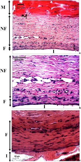
Light microscopy images showing H&E stained subcutaneous tissue above the PU film implant following 4 weeks of implantation (a) and its magnified section (b) and 9 (c), where M is subcutaneous smooth muscle, NF is native fibrous tissue, F is fibrous tissue (capsule) surrounding the implant I.
Electrospinning introduced fibro‐porous structures in 8PU and 12PU membranes. However, when they were implanted in the body, their pore sizes were too small (∼1 μm) to allow infiltration of cells into the bulk of the membranes. Hence, the tissue responses to both 8PU and 12PU were like that observed for nonporous PU film at both time points (Fig. 3). The small pore sizes can be attributed to the nature of deposition of fibers by electrospinning. The fibers fuse at contact points with neighboring fibers resulting in a rigid fibrous mesh.27, 28
Figure 3.
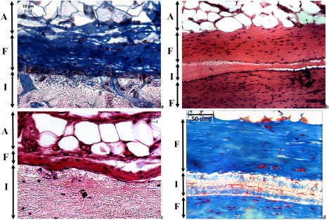
Light microscopy images showing the tissue‐implant interface for: (a, b) 8PU and (c, d) 12PU; at (a, c) 4 weeks and (b, d) 9 weeks of implantation; (a, d) [MT stained and (b, c)] H&E stained sections, where A is subcutaneous fat (adipose), F is fibrous tissue (capsule) surrounding the implant I.
However, 6PU10GE coaxial fiber membranes, having similar pore size (∼1.5 µm), allowed host cell infiltration into its fibro‐porous bulk (Fig. 4). The immediate surface of the host cell infiltrated 6PU10GE membrane, unlike that of 8PU and 12PU, was not covered by dense fibrous encapsulation. But, the cell content in this layer was significantly higher, with primarily macrophages indicating an active resorption of GE [Fig. 4(a–d)]. Some lymphocytes were also observed indicating a mild immune response to GE, which could further accelerate resorption of GE. The blue staining in the MT stained histology sections is collagen. At 4 weeks, hardly any blue staining was seen within the 6PU10GE membrane [Fig. 4(b)]. But by 9 weeks, collagen deposition was seen within the 6PU10GE implant matrix [Fig. 4(d)]. GE, being an extracellular matrix (ECM) derivative, is susceptible to enzymatic degradation, and its resorption would make the thin PU cores discreet and flexible allowing movement of cells within the scaffold. The tiny darkly stained structures within the scaffold indicate cells attached to the individual electrospun fibers along the fiber axis [Fig. 4(a,c)]. Such cell adhesion to fibers also indicates that the cells are fibroblasts. Occasional presence of larger cells within the scaffold was also indicative of infiltration of larger cells (≥10 µm) through displacement of flexible fibers. This result demonstrates that the rigidity due to fusion of neighboring fibers can be overcome by using a degradable coating on the electrospun fiber surface [Fig. 4(a–d)]. Zhang et al. also reported partial cellular infiltration into electrospun membranes having fiber size around 1 μm in an in vitro cell culture study for composite fibers that were electrospun with blended solutions of polycaprolactone and GE.29
Figure 4.
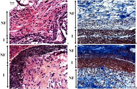
Light microscopy images showing the implant sites for 6PU10GE (a) H&E and (b) MT stained sections at 4 weeks after implantation, and (c) H&E and (d) MT stained section at 9 weeks after implantation, where NF is the native fibrous tissue structure, and I the implant.
In vivo functional efficacy testing
Following surgery for implantation of sensors, all rats recovered normally and survived the duration of the experiments (9 weeks) without any adverse events at the implants sites. The rats weighed 257 ± 18 g at the time of sensor implantation, and gained weight consistently, with average weights of 296 ± 25, 331 ± 24 and 378 ± 30 g at 1, 3 and 9 weeks, respectively.
Effect of anesthesia on blood glucose levels
Glucose tolerance test provides a means to verify the functional efficacy of sensors implanted for continuous glucose monitoring. However, such testing, in the absence of wireless means of logging the sensor output, requires the use of general anesthesia. Anesthetics, in turn, are known for their effect on disruption of glucose homeostasis, and depression of respiratory and cardiovascular systems. Here, we compared pentobarbitone and isoflurane for their effects on blood glucose levels. Pentobarbitone did not affect the blood glucose levels, but isoflurane consistently induced hyperglycemia (Fig. 5). Similar results are widely reported.14, 30, 31, 32, 33 In a similar study, Koschwanez et al. tested the effect of isoflurane and pentobarbitone on blood glucose levels, and used pentobarbitone since it did not cause hyperglycemia for sensor functional efficacy testing.14 They administered a single IP dose of 0.3 mL of 50 mg/mL pentobarbitone (Nembutal Sodium Solution). However, we observed repeated dosing with lower volume of pentobarbitone to be safer at maintaining anesthesia, because the margin between anesthetic and lethal doses for pentobarbitone is very narrow.34 However, concerns are raised because of the low pH of the pentobarbitone solution.35 Due to pain that may be caused by the low pH, use of pentobarbitone as an anesthetic is generally discouraged unless it was for nonrecovery procedures. Similarly, the use isoflurane as an anesthetic for glucose tolerance test is discounted since it offsets the glycemic profile. Despite the offset, we noticed the glycemic profile was comparable to that observed with pentobarbitone [Fig. 5(b,c)]. However, it was also shown that the effect of hyperglycemia induced by isoflurane can be minimized using analgesia.32, 33 We used buprenorphine hydrochloride and carprofen as analgesics to obtain baseline blood glucose levels of 6.52 ± 0.28 and 4.45 ± 0.1 mM/L for isoflurane and pentobarbitone, respectively.
Figure 5.
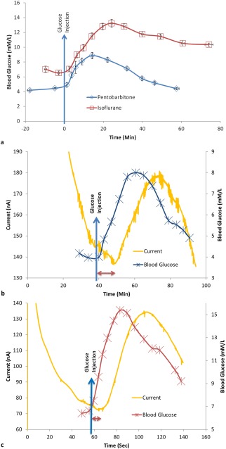
Change in blood glucose concentration: (a) measured using Freestyle Lite blood glucose meter showing the effect of two types of anesthesia on blood glucose levels, (b, c) The typical sensor response current vs. time plot of an implanted sensor and the corresponding change in blood glucose levels measured using a commercial blood glucose monitor for rats. The anesthesia used for the rats in b and c were sodium pentobarbitone (n = 16) and isoflurane (n = 17), respectively. The blue arrow indicates time of injection of a high dose of glucose in the peritoneum. The sensor response delay for the coil‐type glucose biosensor implanted in subcutaneous tissue compared to the corresponding change in blood glucose level is indicated by the double end arrow (b, c).
Upon IP injection of glucose (∼1 g/kg), blood glucose levels rose rapidly, peaked at 8.87 ± 0.45 mM/L and 13.23 ± 0.53 mM/L, respectively, for pentobarbitone and isoflurane and tailed off slowly [Fig. 5(a)]. For isoflurane, it took longer for glucose levels to peak and longer to decrease. The difference can be attributed to the continuous dose of isoflurane for maintaining anesthesia. Despite the baseline increase of blood glucose levels with the use of isoflurane, the dynamics of blood glucose levels as measured by the implanted sensor response current was similar to that measured using the commercial blood glucometer [Fig. 5(c)], which dynamic change in blood glucose levels was also similar to that observed with pentobarbitone [Fig. 5(b)]. Thus, with appropriate analgesia, isoflurane can serve as an anesthetic for glucose tolerance tests in healthy rats.
Effect of electrospun coatings on the function of glucose biosensors implanted in the subcutaneous tissue of rats
The sensor configurations Pt‐GOD‐8PU‐12PU, Pt‐GOD‐EPU‐12PU, Pt‐GOD‐EPU‐6PU10GE, and Pt‐GOD‐EPU were tested for functional efficacy in vivo at 1, 3 and 9 weeks after implantation for each implanted sensor. Examples of typical sensor response current curves measuring glucose levels in interstitial fluid as a function of time along with the corresponding change in blood glucose levels are shown in Figure 5(b,c). The sensor response delay was calculated in relation to changes of glucose level in blood as indicated in Figure 5(b,c).
Premature sensor failure is quite common in implantable glucose monitoring. In this study, 4, 5, 2, and 3 out of 6 sensors were functional at the end of the study period of 9 weeks for Pt‐GOD‐EPU, Pt‐GOD‐8PU‐12PU, Pt‐GOD‐EPU‐12PU, and Pt‐GOD‐EPU‐6PU10GE sensors, respectively. 2 and 1 sensors failed by 3 weeks for Pt‐GOD‐EPU and Pt‐GOD‐8PU‐12PU, respectively. On the other hand, 2 of the 4, and 2 of the 3 nonfunctional sensors in the case of Pt‐GOD‐EPU‐12PU and Pt‐GOD‐EPU‐6PU10GE, respectively, could not be tested due to broken sensor leads. Of the four functional Pt‐GOD‐EPU‐12PU sensors implanted in the rat subcutaneous tissue, two failed by 9 weeks, and of the four functional Pt‐GOD‐EPU‐6PU10GE sensors, one failed by 3 weeks. Essentially, at least 50% of the sensors were functional till the end of the 9‐week study period, which can be attributed to the larger quantity of glucose oxidase immobilized on the cotton‐reinforced coil of the working electrode design tested in this study (Fig. 1). Similar correlation of higher levels of GOD loading leading to longer in vivo sensing life was reported earlier.6
Sensor response delay
The time taken for the implanted glucose biosensors to respond to the high dose of glucose injected in the peritoneum was compared with that in blood and results presented in Figure 6(a). At week 1 after implantation, Pt‐GOD‐8PU‐12PU sensors showed the fastest response to glucose (<10 min), followed by Pt‐GOD‐EPU‐6PU10GE and then Pt‐GOD‐EPU‐12PU. The control sensor Pt‐GOD‐EPU showed the slowest response time of ∼15 min. By 3 weeks of implantation, Pt‐GOD‐EPU sensors showed the fastest response time, while that for other sensors with electrospun coatings increased. The trend at week 9 was comparable with that at week 3, except that the sensor Pt‐GOD‐EPU‐6PU10GE showed a decrease in sensor response time. This decrease resulted in its sensor response time to be on par with that of the control sensor Pt‐GOD‐EPU. The changes in response times could be indicative of the nature of changes in composition of tissue at the sensor tissue interface. The high pore‐volume of the electrospun membranes at week 1 could be responsible for their better permeability to glucose and hence faster response time.11 However, at week 3, the tissue build‐up at their surface could be responsible for the increase in sensor response delay time. In contrast, the control Pt‐GOD‐EPU sensor showed initial slower response to glucose which could be due to poor wetting of its EPU membrane, compared to the fluid filled pores of electrospun membranes. The wetting could have improved with deposition of snugly fit host tissue on the EPU membrane, thus lowering the sensor response time thereafter. The sensor response time for Pt‐GOD‐EPU‐6PU10GE decreasing to the level observed with Pt‐GOD‐EPU control sensor could be due to the resorption of Ge‐shell and replacement with collagenous connective tissue similar to that observed with PU films.
Figure 6.
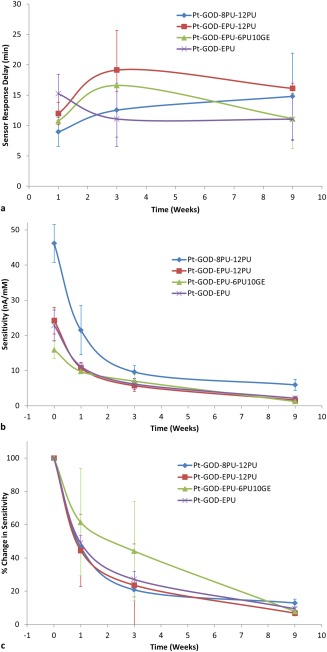
In vivo sensor performance: (a) delay in response to sensing glucose in interstitial fluid for coil‐type glucose biosensors implanted in the subcutaneous tissue in relation change in blood glucose levels as a function of sensor coating configurations; (b) change in sensitivity of glucose biosensors implanted in the subcutaneous tissue of rats; and (c) change in sensitivity of glucose biosensors implanted in the subcutaneous tissue of rats normalized to their preimplantation sensitivities.
Sensitivity of implanted biosensor to glucose
The preimplantation in vitro sensitivity was 46.13 ± 5.36, 22.88 ± 4.31, 24.21 ± 3.76, 15.90 ± 2.40 nA/mM, respectively, for Pt‐GOD‐8PU‐12PU, Pt‐GOD‐EPU, Pt‐GOD‐EPU‐12PU, and Pt‐GOD‐EPU‐6PU10GE [Fig. 6(b)], which sensitivities are significantly higher than the 3.564 ± 0.054 nA/mM reported by Koschwanez et al. for Medtronic MiniMed SOF‐SENSOR™ glucose sensors.14 The higher sensitivities for our sensors can be attributed to larger quantity of GOD loaded on the working electrodes. Furthermore, among the sensors tested in this study, replacing the traditional solvent cast EPU with electrospun 8PU as the mass‐transport limiting membrane more than doubled the in vitro sensitivity. Earlier, when we tested 8PU as the mass transport limiting membrane, the sensitivity increased by about 30% compared to that without a mass transport limiting membrane (Pt‐GOD).10 In contrast, the corresponding change for the traditional EPU mass transport limiting membrane was about 10% decrease. This difference manifested as more than double the sensitivity for Pt‐GOD‐8PU‐12PU compared to Pt‐GOD‐EPU in this study. This can be attributed to an ordered and gradient transmembrane porosity across the 8PU‐12PU electrospun coatings on the Pt‐GOD sensor surface.
As expected, the sensitivity for all sensor configurations decreased with increasing implantation time [Fig. 6(b)]. But, it was interesting to note that the higher the preimplantation sensitivity the higher was the sensitivity in vivo, as observed with Pt‐GOD‐8PU‐12PU sensors. Larger the measured sensor response currents, the lesser will be the signal‐to‐noise ratio. However, when the in vivo sensitivities of the different sensors were normalized to their corresponding preimplantation sensitivities, the percent decrease in sensitivity was similar for all sensors. This proportional decrease in sensor sensitivities with time is indicative of the deactivation of the immobilized GOD on the sensor's working electrodes as reported by Valdes and Moussy,6 which is further reiterated by our result that >50% of the implanted sensors were functional at 9 weeks after implantation. Koschwanez et al. showed that majority of the Medtronic MiniMed SOF‐SENSOR™ glucose sensors (with lower preimplantation sensitivities compared to sensors tested in our study) failed to respond to the glucose bolus within 2 weeks and all sensors failed by 3 weeks.14
When bioactive 6PU10GE coaxial fiber membranes were used as the tissue engineering coatings on the traditional Pt‐GOD‐EPU sensors, the percent decrease in sensitivity was slowest in vivo when compared to the rest of the sensors both at 1 and 3 weeks after implantation [Fig. 6(c)], which can be credited to the prevention of dense fibrous capsule on 6PU10GE surface. However, at 9 weeks the advantage of 6PU10GE coatings was lost due to resorption of GE and replacement with collagen, resulting in sensitivities similar to the traditional Pt‐GOD‐EPU sensors.
CONCLUSION
Fibro‐porous structure of electrospun membranes with average pore sizes of ∼1 µm did not influence the nature of tissue responses compared to nonporous solvent‐cast PU film. However, the bioactive 6PU10GE coaxial fiber membranes, also having similar pore size (∼1.5 µm), allowed host cell infiltration into its fibro‐porous bulk. As mass transport limiting membranes, electrospun 8PU membranes showed higher preimplantation in vitro sensitivity, which translated to higher in vivo sensitivity. Furthermore, the biomimetic 6PU10GE coating prevented fibrous capsule formation on sensor surface, thus increasing sensor sensitivity for at least 3 weeks. To conclude, electrospun membranes can replace traditional mass‐transport limiting membranes as well as function as tissue engineering outer coatings to reliably prolong the in vivo sensing lifetime of implantable glucose biosensors.
CONFLICT OF INTEREST
No benefit of any kind will be received either directly or indirectly by the author(s).
ACKNOWLEDGMENTS
Ning Wang acknowledges the studentship for her Ph.D. from Brunel Institute for Bioengineering, Brunel University. The authors also acknowledge the support and the guidance from Prof. Francis Moussy for this study.
How to cite this article: Burugapalli K, Wijesuriya S, Wang N, Song W. 2018. Biomimetic electrospun coatings increase the in vivo sensitivity of implantable glucose biosensors. J Biomed Mater Res Part A 2018:106A:1072–1081.
REFERENCES
- 1. Helton KL, Ratner BD, Wisniewski NA. Biomechanics of the sensor‐tissue interface – effects of motion, pressure, and design on sensor performance and the foreign body response – part i: Theoretical framework. J Diabetes Sci Technol 2011;5:632–646. [DOI] [PMC free article] [PubMed] [Google Scholar]
- 2. Wisniewski N, Klitzman B, Miller B, Reichert WM. Decreased analyte transport through implanted membranes: Differentiation of biofouling from tissue effects. J Biomed Mater Res 2001;57:513–521. [DOI] [PubMed] [Google Scholar]
- 3. Wisniewski N, Moussy F, Reichert WM. Characterization of implantable biosensor membrane biofouling. Fresenius J Anal Chem 2000;366:611–621. [DOI] [PubMed] [Google Scholar]
- 4. Wisniewski N, Reichert M. Methods for reducing biosensor membrane biofouling. Colloids Surf B Biointerfaces 2000;18:197–219. [DOI] [PubMed] [Google Scholar]
- 5. Brauker JH, Carr‐Brendel V, Tapsak MA. Porous membranes for use with implantable devices. US Patent 8118877; 2012.
- 6. Valdes TI, Moussy F. In vitro and in vivo degradation of glucose oxidase enzyme used for an implantable glucose biosensor. Diabetes Technol Ther 2000;2:367–376. [DOI] [PubMed] [Google Scholar]
- 7. Yu B, Moussy Y, Moussy F. Coil‐type implantable glucose biosensor with excess enzyme loading. Front Biosci 2005;10:512–520. [DOI] [PubMed] [Google Scholar]
- 8. Yu B, Ju Y, West L, Moussy Y, Moussy F. An investigation of long‐term performance of minimally invasive glucose biosensors. Diabetes Technol Ther 2007;9:265–275. [DOI] [PubMed] [Google Scholar]
- 9. Yu B, Moussy Y, Moussy F. Lifetime improvement of glucose biosensor by epoxy‐enhanced PVC membrane. Electroanal 2005;17:1771–1779. [Google Scholar]
- 10. Wang N, Burugapalli K, Song W, Halls J, Moussy F, Ray A, Zheng Y. Electrospun fibro‐porous polyurethane coatings for implantable glucose biosensors. Biomaterials 2013;34:888–901. [DOI] [PMC free article] [PubMed] [Google Scholar]
- 11. Wang N, Burugapalli K, Song W, Halls J, Moussy F, Zheng Y, Ma Y, Wu Z, Li K. Tailored fibro‐porous structure of electrospun polyurethane membranes, their size‐dependent properties and trans‐membrane glucose diffusion. J Memb Sci 2013;427:207–217. [DOI] [PMC free article] [PubMed] [Google Scholar]
- 12. Wang N, Burugapalli K, Wijesuriya S, Far MY, Song W, Moussy F, Zheng Y, Ma Y, Wu Z, Li K. Electrospun polyurethane‐core and gelatin‐shell coaxial fibre coatings for miniature implantable biosensors. Biofabrication 2013;6:015002. [DOI] [PMC free article] [PubMed] [Google Scholar]
- 13. Reddy SM, Vagama PM. Surfactant‐modified poly(vinyl chloride) membranes as biocompatible interfaces for amperometric enzyme electrodes. Anal Chim Acta 1997;350:77–89. [Google Scholar]
- 14. Koschwanez HE, Yap FY, Klitzman B, Reichert WM. In vitro and in vivo characterization of porous poly‐L‐lactic acid coatings for subcutaneously implanted glucose sensors. J Biomed Mater Res 2008;87A:792–807. [DOI] [PMC free article] [PubMed] [Google Scholar]
- 15. Lee JH, Kopecek J, Andrade JD. Protein‐resistant surfaces prepared by PEO‐containing block copolymer surfactants. J Biomed Mater Res 1989;23:351–368. [DOI] [PubMed] [Google Scholar]
- 16. Sharkawy AA, Klitzman B, Truskey GA, Reichert WM. Engineering the tissue which encapsulates subcutaneous implants. I. Diffusion properties. J Biomed Mater Res 1997;37:401–412. [DOI] [PubMed] [Google Scholar]
- 17. Sharkawy AA, Klitzman B, Truskey GA, Reichert WM. Engineering the tissue which encapsulates subcutaneous implants. II. Plasma‐tissue exchange properties. J Biomed Mater Res 1998;40:586–597. [DOI] [PubMed] [Google Scholar]
- 18. Sharkawy AA, Klitzman B, Truskey GA, Reichert WM. Engineering the tissue which encapsulates subcutaneous implants. III. Effective tissue response times. J Biomed Mater Res 1998;40:598–605. [DOI] [PubMed] [Google Scholar]
- 19. Brauker JH, Carr‐Brendel VE, Martinson LA, Crudele J, Johnston WD, Johnson RC. Neovascularization of synthetic membranes directed by membrane microarchitecture. J Biomed Mater Res 1995;29:1517–1524. [DOI] [PubMed] [Google Scholar]
- 20. Ju YM, Yu B, Koob TJ, Moussy Y, Moussy F. A novel porous collagen scaffold around an implantable biosensor for improving biocompatibility. I. In vitro/in vivo stability of the scaffold and in vitro sensitivity of the glucose sensor with scaffold. J Biomed Mater Res 2008;87A:136–146. [DOI] [PubMed] [Google Scholar]
- 21. Ju YM, Yu B, West L, Moussy Y, Moussy F. A novel porous collagen scaffold around an implantable biosensor for improving biocompatibility. II. Long‐term in vitro/in vivo sensitivity characteristics of sensors with NDGA‐ or GA‐crosslinked collagen scaffolds. J Biomed Mater Res 2010;92:650–658. [DOI] [PubMed] [Google Scholar]
- 22. Sanders JE, Cassisi DV, Neumann T, Golledge SL, Zachariah SG, Ratner BD, Bale SD. Relative influence of polymer fiber diameter and surface charge on fibrous capsule thickness and vessel density for single‐fiber implants. J Biomed Mater Res 2003;65A:462–467. [DOI] [PubMed] [Google Scholar]
- 23. Trzebinski J, Moniz AR‐B, Sharma S, Burugapalli K, Moussy F, Cass AEG. Hydrogel membrane improves batch‐to‐batch reproducibility of an enzymatic glucose biosensor. Electroanalysis 2011;23:2789–2795. [Google Scholar]
- 24. Khorshidi S, Solouk A, Mirzadeh H, Mazinani S, Lagaron JM, Sharifi S, Ramakrishna S. A review of key challenges of electrospun scaffolds for tissue‐engineering applications. J Tissue Eng Regen Med 2016;10:715–738. [DOI] [PubMed] [Google Scholar]
- 25. Iatridis JC, Wu J, Yandow JA, Langevin HM. Subcutaneous tissue mechanical behavior is linear and viscoelastic under uniaxial tension. Connective Tissue Res 2003;44:208–217. [PubMed] [Google Scholar]
- 26. Burugapalli K, Pandit A. Characterization of tissue response and in vivo degradation of cholecyst‐derived extracellular matrix. Biomacromolecules 2007;8:3439–3451. [DOI] [PubMed] [Google Scholar]
- 27. Bhardwaj N, Kundu SC. Electrospinning: A fascinating fiber fabrication technique. Biotechnol Adv 2010;28:325–347. [DOI] [PubMed] [Google Scholar]
- 28. Eichhorn SJ, Sampson WW. Statistical geometry of pores and statistics of porous nanofibrous assemblies. J R Soc Interface 2005;2:309–318. [DOI] [PMC free article] [PubMed] [Google Scholar]
- 29. Zhang Y, Ouyang H, Lim CT, Ramakrishna S, Huang Z‐M. Electrospinning of gelatin fibers and gelatin/PCL composite fibrous scaffolds. J Biomed Mater Res 2005;72B:156–165. [DOI] [PubMed] [Google Scholar]
- 30. Zuurbier CJ, Keijzers PJM, Koeman A, Van Wezel HB, Hollmann MW. Anesthesia's effects on plasma glucose and insulin and cardiac hexokinase at similar hemodynamics and without major surgical stress in fed rats. Anesth Analg 2008;106:135–142. [DOI] [PubMed] [Google Scholar]
- 31. Tanaka K, Kawano T, Tomino T, Kawano H, Okada T, Oshita S, Takahashi A, Nakaya Y. Mechanisms of impaired glucose tolerance and insulin secretion during isoflurane anesthesia. Anesthesiology 2009;111:1044–1051. [DOI] [PubMed] [Google Scholar]
- 32. Behdad S, Mortazavizadeh A, Ayatollahi V, Khadiv Z, Khalilzadeh S. The effects of propofol and isoflurane on blood glucose during abdominal hysterectomy in diabetic patients. Diabetes Metab J 2014;38:311–316. [DOI] [PMC free article] [PubMed] [Google Scholar]
- 33. Schricker T, Galeone M, Wykes L, Carli F. Effect of desflurane/remifentanil anaesthesia on glucose metabolism during surgery: a comparison with desflurane/epidural anaesthesia. Acta Anaesthesiol Scand 2004;48:169–173. [DOI] [PubMed] [Google Scholar]
- 34. Flecknell PA. Chapter 6—Anaesthesia of common laboratory species: special considerations Laboratory Animal Anaesthesia, 3rd ed. San Diego: Academic Press; 2009. p 181241. [Google Scholar]
- 35. Svendsen O, Kok L, Lauritzenã B. Nociception after intraperitoneal injection of a sodium pentobarbitone formulation with and without lidocaine in rats quantified by expression of neuronal c‐fos in the spinal cord—A preliminary study. Lab Anim 2007;41:197–203. [DOI] [PubMed] [Google Scholar]