Abstract
Total hip replacement (THR) failure due to mechanically assisted crevice corrosion within modular head-neck taper junctions remains a major concern. Several processes leading to the generation of detrimental corrosion products have been reported in first generation modular devices. Contemporary junctions differ in their geometries, surface finishes, and head alloy. This study specifically provides an overview for CoCrMo/CoCrMo and CoCrMo/Ti6Al4V head- neck contemporary junctions. A retrieval study of 364 retrieved THRs was conducted which included visual examination and determination of damage scores, as well as the examination of damage features using scanning electron microscopy. Different separately occurring or overlapping damage modes were identified that appeared to be either mechanically or chemically dominated. Mechanically dominated damage features included plastic deformation, fretting, and material transfer, whereas chemically dominate damage included pitting corrosion, etching, intergranular corrosion, phase boundary corrosion, and column damage. Etching associated cellular activity was also observed. Furthermore, fretting corrosion, formation of thick oxide films, and imprinting were observed which appeared to be the result of both mechanical and chemical processes. The occurrence and extent of damage caused by different modes was shown to depend on the material, the material couple, and alloy microstructure. In order to minimize THR failure due to material degradation within modular junctions, it is important to distinguish different damage modes, determine their cause, and identify appropriate counter measures, which may differ depending on the material, specific microstructural alloy features, and design factors such as surface topography.
Keywords: corrosion, fretting, implant retrieval, joint replacement, electron microscopy
Introduction
Total hip replacement (THR) is a very successful procedure, but there are still a considerable number of premature implant failures leading to revision surgery. Considering the hundreds of thousands of procedures conducted each year, even a small incidence of failure has a large impact.1 A considerable portion of THR failures can be attributed to material degradation within the modular taper junction between the femoral head and stem.2,3 Most concerning is the generation of corrosion products that can cause adverse local tissue reactions (ALTRs). Such tissue reactions are known to be painful and to result in extensive tissue necrosis, thus complicating revision procedures.2,4,5 Recent reports suggest that the incidence of ALTR related implant failure may be higher than initially recognized, especially because its diagnosis can be difficult, as ALTR can mimic infections.6–8
ALTRs are triggered by ionic and particulate corrosion products generated during corrosion processes within the modular taper junction. The complex corrosion processes have been summarized as mechanically assisted crevice corrosion (MACC).9 However, other underlying modes of corrosion have also been observed. When the problem of modular junction corrosion was first analyzed in the early 1990’s, several modes were apparent, including etching, fretting, intergranular corrosion, pitting, film formation and selective leaching.9,10 Subsequently, other damage modes have been identified including imprinting (transfer of the stem taper topography to the head taper) and cell induced corrosion.11–13 Other damage features such as needle-like protrusions and toggle damage have also been observed.11,14 Additionally, different damage modes often overlap within the same area. Knowledge of the occurrence of different modes of corrosion and other damage modes is of great importance to determine the appropriate counter measures to address design, surface modification or surgical technique.
It was the purpose of this study to determine what damage modes occur on the head and stem taper surfaces within a group of contemporary THR modular junctions, and how they relate to specific damage scores. Particularly, we were interested in the two most commonly occurring material alloy couples which are either a CoCrMo head and stem (Co/Co) or a CoCrMo alloy head paired with a Ti6Al4V stem (Co/Ti). We addressed the following two research questions: (1) How frequently did specific damage scores (minimal, mild, moderate, severe) occur on taper surfaces of Co/Co and Co/Ti THR modular junctions that were surgically retrieved? (2) Which specific damage modes occurred on head and stem tapers of both material couples, and how frequently did these occur within the subset study group? In order to answer these research questions, a retrieval study was conducted, in which taper damage scores were determined and the corresponding damage modes were identified by means of scanning electron microscopy (SEM).
Materials and Methods
For this study, only contemporary THR designs were considered which included all Co/Co and Co/Ti head/stem pairs in our retrieval collection that had been implanted after 1997, independent of the type of acetabular bearing surface. Considering these inclusion/exclusion criteria, 364 retrievals were available, which had been retrieved consecutively between 2004 and 2015. There were 165 Co/Co couples and 199 Co/Ti couples from 13 different manufacturers (Table 1). The mean time in situ was 3.6 years ± 3.8 years and 1.5 years ± 2.2 years (p<0.001, Mann-Whitney), respectively. The difference in implant duration was attributable to the reason for removal. Forty-six percent of the Co/Ti coupled implants were retrieved after less than 3 months in situ, compared to only 16% of the Co/Co implants. The two most common reasons for the early removal of the Co/Ti implants were infection (51%) and periprosthetic fractures (33%). Conversely, 50% of the Co/Co implants were removed after 24 months, compared to 29% of the Co/Ti implants. Aseptic loosening and infection were the most common reasons for revision overall (Table 2).
Table 1.
Information on retrieved implant
| Couple | N | Time In Situ (yr) | Head Size | Bearing type | Manufacturer |
|---|---|---|---|---|---|
| Co/Co | 165 | 3.6 SD 3.8 | 28 (N=53), 32 (N=50), 36 (N=32) | MoP (N=137), MoM (N=6), Hemi (N=22) | Zimmer (N= 103), DePuy (N=24), WMT (N=7), Smith&Nephew (N=12), Richards (N=11), Stryker (N=2), Howmedica (N=4), Other (N=2) |
| Co/Ti | 199 | 1.5 SD 2.2 | 28 (N=17), 32 (N=114), 36 (N=37) | MoP (N=169), MoM (N=21), Hemi (N=3) Unknown (N=6) |
Zimmer (N= 109), DePuy (N=39), WMT (N=21), Smith&Nephew (N=13), Biomet (N=9), Stryker (N=4), Other (N=4) |
| p | 0.1 | <0.001* |
Table 2.
Reasons for implant failure
| Reason for revision | Total | Co/Co | Co/Ti |
|---|---|---|---|
| Aseptic loosening | 115 | 69 | 46 |
| ALTR | 5 | 3 | 2 |
| Infection | 159 | 61 | 98 |
| Instability | 22 | 15 | 7 |
| Periprosthetic fx | 49 | 12 | 37 |
| Pain | 4 | 0 | 4 |
| Other | 5 | 3 | 2 |
| Not available | 5 | 2 | 3 |
The primary articulation was metal-on-polyethylene (MoP) in 84% of cases, metal-on-metal in 7% of cases, and 7% of cases where hemi-arthroplasties. No bearing surface information was available for 6 couples. Most femoral heads were 32 mm in diameter (n=164), and head sizes ranged from 22 mm to 57 mm (Table 1). Among the CoCrMo stems, 53% had some type of a sintered structure for bone ingrowth. Ninety-one percent of the Ti-alloy stems had a porous coating and had been inserted without cement.
All femoral heads and stems were decontaminated in 10% neutral buffered formalin for a minimum of 72 hours after which they were rinsed in running tap water for 15 minutes. Any head tapers requiring further cleaning to visualize damage patterns were cleaned using a soft toothbrush and warm water. The head and stem taper surfaces were scored using a stereo microscope (SMZ-U; Nikon, Melville, NY, USA) based on a visual damage scoring system (modified from Goldberg score10,15) where damage is scored from least to most severe as minimal (1), mild (2), moderate (3), or severe (4). The score included damage resulting from fretting and corrosion combined. Two observers scored the surfaces (RMU and DJH). In the case of disagreement in scores between the two observers, the observers discussed and came to a consensus on the score. Differences in the mean taper and head scores were compared using the Mann-Whitney test. The data are presented as mean and standard deviation.
Local damage modes were analyzed for a subset of representative components that were retrieved between 2004 and 2014, including femoral stems from 21 Co/Co and 16 Co/Ti couples, and femoral heads from 18 Co/Co and 17 Co/Ti couples. The taper surfaces were viewed under a SEM (JSM 6490 LV, JEOL, Peabody, MA). SEM analysis of the taper surfaces was conducted at magnifications between 100× to 5000×. The chemical compositions of deposits and films were analyzed by energy dispersive x-ray spectroscopy (EDS) (INCA Energy 350, Oxford Instruments, Concord, MA). In selected cases, the entire taper surface was imaged using an optical coordinate machine (Ortholux, Redlux, Southampton, UK). For the head tapers, a mold was made and measured according to a previously described method.16 The prevalence of specific damage modes between material couples was tested with the Chi-Square method.
The prevalence of all global damage modes was determined for moderately and severely damaged taper surfaces. The only exception was phase boundary corrosion, which is naturally highly dependent on the hard phase volume fraction. It was previously shown that hard phase content can differ between manufacturers, but also within a single design.17–19 Since a metallographic analysis was not in the scope of this study, it was not possible to relate the occurrence of phase boundary corrosion to the microstructure.
Results
Damage Score Distribution
There was only a small difference in average stem taper damage score between Co/Co couples and Co/Ti couples (1.5±0.9, 1.6±0.8, respectively, p=0.011). For the Co/Co couples, 74% of stem tapers had minimal damage, 11% had mild damage, 8% had moderate damage and 7% exhibited severe damage (Table 3). The Co/Ti couples had a different distribution with 57% of stem tapers showing no considerable damage, 30% had mild damage, 11% had moderate damage, and only 3% had severe damage. Using a Chi-square test there was only a significant difference (<0.001) in the group of mildly damaged components (Figure 1). However, there tended to be a greater prevalence for CoCrMo stems to have minimal or severe damage compared to Ti6Al4V stems (Figure 1).
Table 3.
Average head and stem damage scores for all retrieved component, and breakdown by damage score
| Couple | Average Stem Taper Score | Average Head Taper Score | Stem Taper Damage [%] | Head Taper Damage [%] | ||||||
|---|---|---|---|---|---|---|---|---|---|---|
| Minimal | Mild | Moderate | Severe | Minimal | Mild | Moderate | Severe | |||
| All | 1.5 SD 0.8 | 1.7 SD 1 | 65 | 21 | 10 | 4 | 64 | 16 | 11 | 9 |
| Co/Co | 1.5 SD 0.9 | 1.6 SD 1 | 74 | 11 | 8 | 7 | 70 | 11 | 8 | 10 |
| Co/Ti | 1.6 SD 0.8 | 1.7 SD 1 | 57 | 30 | 11 | 3 | 59 | 20 | 14 | 8 |
| p | 0.011 | 0.069 | 0.603 | <0.001 | 0.237 | 0.134 | 0.948 | 0.005 | 0.042 | 0.862 |
Figure 1.
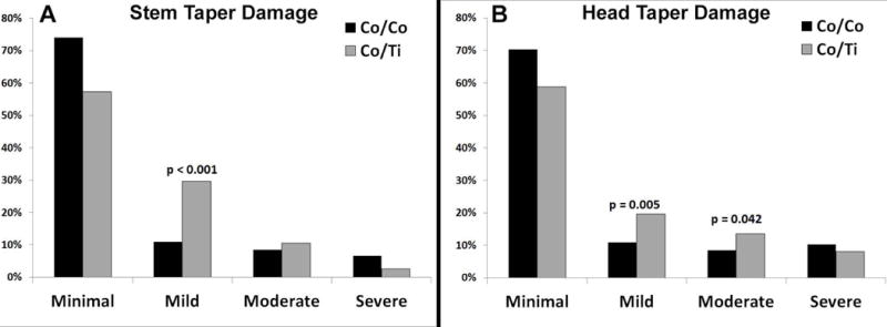
Bar diagrams illustrating the prevalence of minimally, mildly, moderately and severely damaged stem (A) and head (B) tapers for Co/Co couples and for Co/Ti couples.
Co/Co couples and Co/Ti couples also had comparable average head taper damage scores (1.6±1, 1.7±1, respectively, p=0.069). The head tapers of Co/Co couples exhibited minimal damage in 70% of cases, mild damage in 11%, moderate damage in 8%, and severe damage in 10% of cases (Table 3). The head tapers of Co/Ti couples had no considerable damage in 59% of cases, mild damage in 20%, moderate damage in 14%, and severe damage in 8% of cases (Table 3). Head tapers of Co/Ti couples were more likely to have mild (p=0.005) or moderate (p=0.042) damage than head tapers of Co/Co couples (Figure 1).
Damage Features and Damage Modes
In both Co/Co and Co/Ti couples we observed damage features indicative of the following local damage modes: plastic deformation, cyclic creep, material transfer, mechanically and electrochemically dominated fretting, pitting corrosion, etching, intergranular corrosion, phase boundary corrosion, film and deposit formation, and cell induced etching. We also found the following global damage modes: toggle damage, imprinting, and column damage. The occurrence of specific damage modes differed between material couples, head and stem tapers, and damage scores (Figure 2). The damage features of each local and global damage mode will be described in detail below.
Figure 2.
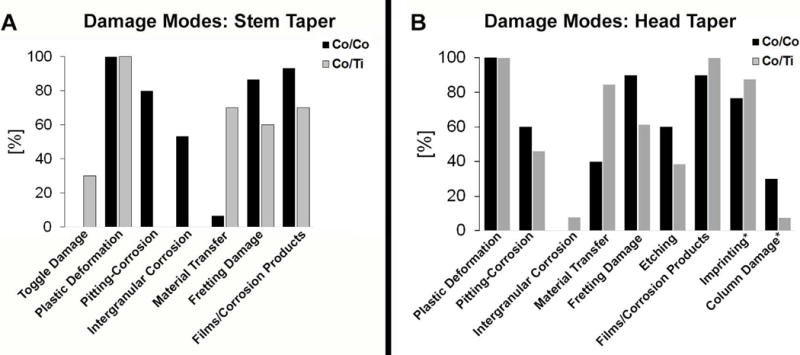
Bar graphs illustrating the prevalence of specific damage modes on moderately to severely damaged stem tapers (A), and head tapers (B). Numbers are based on the subset group that was analyzed by SEM, except for cases marks with (*) which include all moderately to severely damaged tapers.
Plastic deformation, material transfer, toggle damage
The most commonly occurring damage feature was local flattening of machining mark peaks by plastic deformation (Figure 3). Local flattening of machining mark peaks was most dominant in stem tapers with minimal to mild damage. The flattened machining mark width ranged from 1.8 to 93.4 μm for CoCrMo stems and 0.9 to 206 μm for Ti6Al4V stems (Figure 3). The flattened peaks often exhibited grooves which resembled the result of a ploughing mechanism. In most of the cases, such grooves were oriented in the proximal-distal direction. The extent of both machining mark flattening and the occurrence of grooves was most dominant on Ti6Al4V stem tapers (Figure 3C). Peak flattening, grooves, and material transfer was observed to an extreme extent in cases where toggling damage occurred (Figure 3D). Toggle damage was globally characterized as corresponding stem and head taper damage scars on the proximal superior and the distal inferior ends. For stem tapers of Co/Co couples, no evidence of toggle damage was observed. Conversely, for stem tapers of Co/Ti couples, toggle damage was seen in 30% of cases. Plastic deformation was seen in all cases in head and stem tapers of both Co/Co couples and Co/Ti couples. The stem taper in Figure 3D exhibited severe plastic deformation along with proximal-distal grooves, whereas the head taper was covered with strongly adhering titanium oxide. Another frequent finding, unique to Co/Ti couples, was material transfer from the Ti6Al4V stem to the CoCrMo head (Figure 4A). 70% of stem tapers and 85% of head tapers in Co/Ti couples had evidence of material transfer and related surface break-outs. Large flakes of titanium rich material covering substantial areas of the head taper were observed in the SEM (Figures 4A, B). These areas were not necessarily limited to the machining mark peaks, but could span several machining marks. Besides just titanium, the chemical composition of the transferred material did in some cases contain aluminum and vanadium, thus reflecting the actual Ti6AL4V composition (Figure 4A, inset). In other cases, transferred material contained mainly titanium along with chromium, molybdenum and a considerable oxygen peak, indicative of an accumulation of mixed oxides (Figure 4C).
Figure 3.
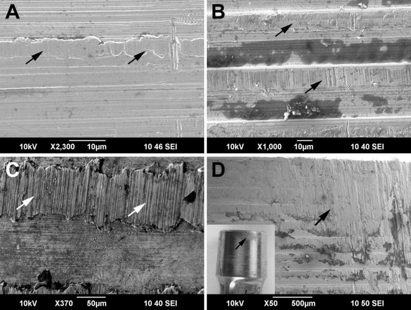
SEM images of deformed machining marks with arrows indicating the following features: A) Flattened machining mark peak on a CoCrMo alloy head coupled with a CoCrMo alloy stem, B) Flattened machining mark peaks with groves in proximal/distal direction on a CoCrMo head coupled with a Ti6Al4V stem, C) Flattened machining mark peak on a Ti-alloy stem taper. The flattened area stretches over 100 micrometers and exhibits deep grooves in the proximal distal direction, D) SEM image of a severely deformed area that was subjected to toggling damage. The inset photograph of the entire stem taper shows the extent of the damage mark, which can be seen by eye. For all images, the tapers are oriented proximal (top) to distal (bottom).
Figure 4.
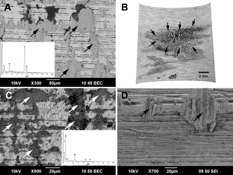
A) Back scatter electron (BSE) SEM image of a Co/Ti head taper surface. Grey areas (arrows) represent flakes of Ti6Al4V that appear to have transferred onto the head taper surface. The EDS spectrum (inset) exhibits all three alloying elements (Ti, Al, V) indicating that adhesion took place. B) 3D reconstruction of the same head taper surface based on optical CMM data. It can be seen that a considerably large area is affected by Ti6Al4V alloy material transfer (darker area, arrows). C) BSE image of a Co/TI head taper surface exhibiting large amounts of transferred material (arrows). The EDS spectrum indicates the presence of Cr, Mo, Ti and oxygen, and little to evidence of Al and V. Based on chemical composition and appearance, it appears an accumulation of oxidized particles and corrosion products took place rather than material transfer due to adhesion. D) Surface of a Ti6Al4V stem taper which exhibits material breakouts due to material transfer (arrows). For all images, the tapers are oriented proximal (top) to distal (bottom).
On the stem taper side, material transfer was mainly characterized by material breakout resulting in large flat depressions (Figure 4D). On stem tapers of Co/Co couples, material transfer occurred in a few cases (7%), and the affected area was comparably small. Here it appeared that small flakes would detach from either the head or the stem taper and transfer to the other. Head tapers of Co/Co couples had material transfer in 40% of cases.
Fretting and fretting corrosion damage features
Damage features indicative of fretting were observed mainly on head and stem taper surfaces of both material couples. Fretting occurred in 87% of stem tapers for Co/Co couples and 60% of stem tapers for Co/Ti couples. Co/Co couples had fretting damage in 90% of head tapers, and Co/Ti couples had fretting damage in 62% of head tapers. This damage feature pointed to either a mechanically dominated damage mode (fretting) or an electrochemically dominated damage mode (fretting corrosion). Mechanically dominated fretting was characterized by fine ridges on the flattened machining mark peaks that were in some cases oriented perpendicular to the taper axis, and were in other cases randomly oriented (Figure 5A, B). Electrochemically dominated fretting marks were characterized by elongated pits that stretched roughly along the taper axis (Figure 5C). Both mechanically and electrochemically dominated fretting damage features occurred frequently on stem tapers with moderate to severe damage, and could appear separately from one another or in combined form (Figure 5D). Often machining mark peaks were completely disrupted, and the fretting marks occurred within the troughs of the initial machining mark topography.
Figure 5.
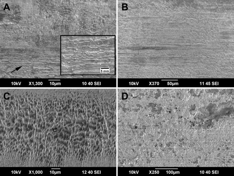
Fretting and fretting corrosion damage on CoCrMo alloy stem tapers (taper axis is vertical in all images) : A) Typical damage features of mechanically induced fretting wear. The lower half of the image shows fine ridges (arrow and higher magnification inset) that are usually located in areas of former machining marks and oriented perpendicular to the taper axis. B) SEM image of randomly oriented mechanically induced fretting marks after complete disruption of the initial machining mark topography. C) SEM image showing elongated pits, a typical damage feature of electrochemically-dominated fretting marks. D) Example of overlapping fretting damage features that were caused by mechanical and electrochemical fretting processes. For all images, the tapers are oriented proximal (top) to distal (bottom).
Pitting corrosion and etching
Evidence of pitting corrosion was frequently observed on CoCrMo stem tapers (80%) and some head tapers (60% for head tapers of Co/Co couples and 46% for head tapers of Co/Ti couples) with severe damage. It was characterized by a large accumulation of round pits with a size range of about 0.1 to 12 micrometers. Such pitting most commonly occurred in the troughs of the machining mark topography in between flattened and mechanically damaged peaks (Figure 6A, B). However, some evidence of pits was found on deformed peaks as well. On some head and stem tapers, machining marks were completely disrupted, and large areas were covered by pits independent of the original topography (Figure 6C, D). In such cases, areas with pitting corrosion and fretting were largely overlapping. Pitted areas were also associated with underlying etching which was characterized by the visualization of crystallographic features such as slip planes (Figure 7A).
Figure 6.
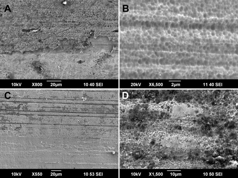
A) SEM image of a CoCrMo stem taper exhibiting pitting. Pitting was characterized by areas covered with fine round pits. It appeared that pits occurred first within in troughs of the machining mark topography, then expanded to other areas as damage progressed. B) Close up image of a pitted area of a CoCrMo stem taper. C) Pitting also occurred in the non-contact area of femoral heads. Due to the shallower machining mark topography, pitting was independent of machining mark troughs. D) Close-up image of a head taper surface that underwent complete disruption of the initial surface due to pitting corrosion. For all images, the tapers are oriented proximal (top) to distal (bottom).
Figure 7.
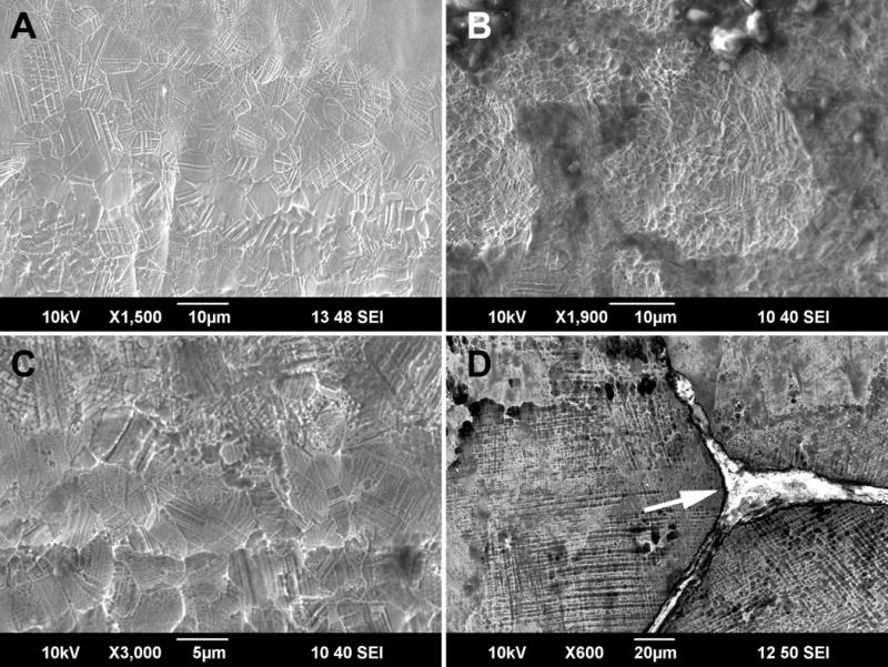
A) Typical damage feature on CoCrMo head taper associated with etching with visible fine grain structure (grain size of ~8μm), twin boundaries, and slip planes. B) In some cases, the head taper surface exhibited a higher density of slip planes, fine pits and the presence of a thin carbon rich film associated with etching. C) Similar etching features were also found on CoCrMo stem tapers that were made from wrought CoCrMo alloy, however, this appeared to have been the case for a only a few THR designs based on the etching damage patterns observed. D) Most stem tapers were made from cast CoCrMo alloy, and in cast CoCrMo alloys etching is less obvious due to the large grain size. Yet, etching did occur as shown by the visualization of slip planes in this image. Also, there appeared to be a slight step between grains indicating different corrosion rates depending on grain orientation. This image also shows the result of intergranular corrosion on cast alloy samples resulting in wide trenches that are partially or entirely filled with carbon rich organic residue (arrow).
CoCrMo head tapers with moderate to severe damage often exhibited large areas of etching (Figure 7B–C). Sixty percent of head tapers in Co/Co couples and 38% of head tapers in Co/Ti couples had evidence of etching. Etching on head tapers was easy to identify as visible slip planes, fine grain structure, and twin boundaries due to the small grain size of the wrought alloy head taper. Etching occurred on cast alloy stem tapers as well but was less obvious due to the significantly larger grain size. In some cases etching was present on cast alloy stem tapers, characterized by oriented pits and height differences between grains (Figure 7D). Ti6Al4V stems did not exhibit etching or widespread pitting corrosion. However, a few cases exhibited areas with accumulations of pits. It is not clear if such pits were formed on the surface, or if they were the result of the agglomeration of wear debris subsequently forming a porous film.
Intergranular and phase boundary corrosion
CoCrMo stem tapers with severe corrosion did, in some cases (n=9), also undergo intergranular corrosion. This damage type was characterized by large areas of material dissolution along the grain boundaries (Figure 8A, B). Interestingly, intergranular corrosion was only observed in components which had a sintered coating on the stem. The width of the resulting trenches ranged from 0.2 to 27.3 μm. Trenches were often partially or entirely refilled with carbon rich matter of presumably organic origin (Figure 7D). In many cases, remains of hard phases such as carbides or intermetallic phases were observed within the trenches (Figure 8C). Hard phases often occurred along the grain boundaries of cast alloys as previously reported20. Hard phases also sometimes occurred within grains. In such cases, phase boundary corrosion was commonly present leading to complete removal of hard phases, and subsequent holes as big as several tens of micrometers in diameter that appeared to be refilled by organic matter like that seen in the trenches left by intergranular corrosion (Figure 8D).
Figure 8.
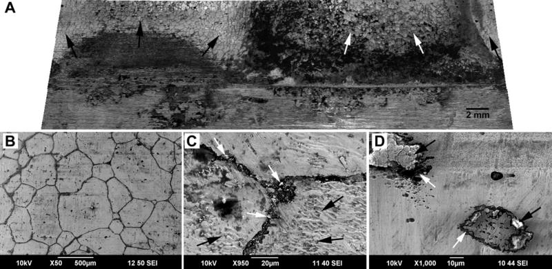
A) 3D reconstruction of a severely damaged CoCrMo alloy stem taper. The surface was affected by intergranular corrosion over nearly the entire contact area (arrows). B) SEM image of an area affected by intergranular corrosion. C) Close up image of a grain boundary that underwent severe material dissolution. Locally hard phase fragments can be detected that are located at the grain boundaries (white arrows). In this case, there was clear evidence of fretting marks on the bordering grains (black arrows). D) SEM image of a mixed hard phase located within the grain of a cast CoCrMo alloy stem taper. It can be seen that there was considerable material loss around the hard phase due to phase boundary corrosion (white arrows). In the upper left corner holes and voids can be seen that are the result of phase boundary corrosion and subsequent hard phase detachment from the surface. Those holes have partly refilled with organic residue and mixed metal oxides (black arrows). Areas around hard phases were also affected by pitting corrosion. For all images, the tapers are oriented proximal (top) to distal (bottom).
Film formation and deposits
Film or flake-like metal oxides and composites of chromium phosphates (CrPO4) were the most commonly occurring deposits. Thick flake-like deposits of chromium oxide were the most common and could be found on both head and stem tapers, often as a mixture with molybdenum oxides (Figure 9A). Stem tapers with high damage scores often exhibited disrupted machining marks partially replaced by thick oxide films. In areas where the thick oxide film flaked off (either in vivo or during disassembly of the implant after removal) fretting or pitting corrosion damage features were observed underneath (Figure 9A). Oxide films on the head taper were usually thinner than those of the stem taper and were often titanium oxide. Chromium phosphate deposits were also a common occurrence, and occurred mostly in the distal area of either head or stem tapers in both material couples (Figure 9B). In some cases, carbonaceous films were observed within the troughs of the surface topography. These films often exhibited strong carbon and molybdenum peaks within the EDS spectrum (Figure 9C).
Figure 9.
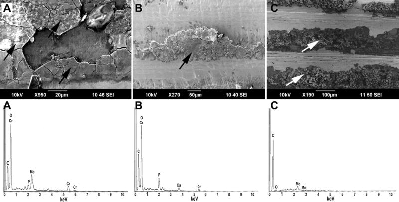
A) SEM image of thick deposit films covering an area of a CoCrMo stem taper that was affected by pitting corrosion. The EDS spectrum exhibited a prominent oxygen peak along with chromium and molybdenum, thus indicating that the deposits consisted mainly of mixed oxides. Cobalt was not present within the film. B) Another typical deposit (here on a CoCrMo head taper) that is usually located toward the distal end of the stem taper and around the opening of the head taper. The EDS spectrum revealed a prominent peak of phosphorus along with chromium and oxygen, thus confirming the presence of chromium phosphate. C) A Ti-alloy stem taper with another type of deposit, which was a carbonaceous- rich film that also exhibited a molybdenum peak, but no other metal. Often these deposits accumulated within the troughs of the stem taper topography. For all images, the tapers are oriented proximal (top) to distal (bottom).
Imprinting
We found several cases in which the rougher topography of the stem taper imprinted into the smoother head taper. This global damage feature was often visible with the naked eye and was commonly referred to as imprinting.12 Imprinting occurred in both Co/Co or Co/Ti material couples (Figure 10). Imprinting was present in 77% of head tapers of Co/Co couples and in 88% of head tapers of Co/Ti couples. Head tapers with imprinting often had a severe damage score. However, at a first glance imprinting may not be obvious because the overall appearance of the imprinted area does not necessarily exhibit other damage features, and can even have a clean and shiny appearance with no films or deposits. In the SEM, the underlying damage process of imprinting is also not obvious due to the smooth appearance of the surface.
Figure 10.
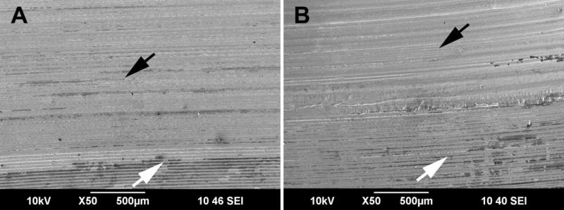
SEM images showing the imprint of the deeper machining mark topography of the stem taper (black arrows) into the smoother surface of a head taper (white arrows) for A) a Co/Co, and B) a Co/Ti modular junction. In both cases the imprinted surface on the head taper was fairly clean with only minimal amounts of deposits or organic residue. For all images, the tapers are oriented proximal (top) to distal (bottom).
Column damage
Another global damage feature on head tapers was the occurrence of a column-like banded pattern that stretched in the proximal-distal direction (Figures 11A, B and 12A, B). 30% of head tapers of Co/Co couples and 8% of head tapers of Co/Ti couples had column damage. In most cases these bands started in the proximal area and ended half way towards the distal opening (Figure 11A). In some cases, especially shorter tapers (e.g. 10 mm), the entire head taper surface was affected (Figure 11B). These bands were independent of the initial surface topography and thus were not entirely in contact with the stem taper surface (Figure 12A). Therefore, its occurrence appeared not to be linked to wear or a mechanical interaction. The band width stretched over several grains, and bands were associated with etching damage (Figure 12B). In many areas, the depressions of the column damage pattern were filled with organic residue.
Figure 11.
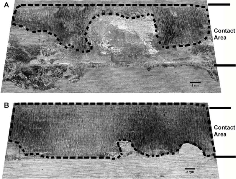
Unwrapped 3D reconstructions of severely damage head tapers that exhibit column damage. Column damage was characterized by a banded structure that was strongly oriented in proximal-distal direction, parallel to the taper axis. A) On this head taper it can be see that column damage (marked area) started out on the proximal end of the taper (top of image A) and progress towards the middle in the distal direction. The column damage pattern did not cover the entire contact area between head and stem taper. B) In this case almost the entire head taper surface was affected by column damage (marked area). It appears that it even reached slightly outside of the contact area on the proximal end (top of image B). For all images, the tapers are oriented proximal (top) to distal (bottom).
Figure 12.
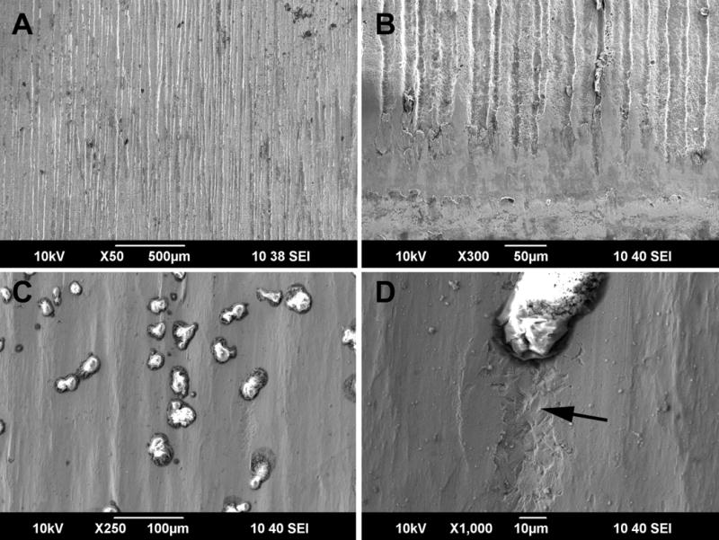
A) SEM micrograph of column damage on a femoral head taper that is characterized by deep grooves or troughs in proximal distal direction. B) Close up image on column damage showing the etched appearance with in the troughs of the damage pattern. Locally, organic residue has accumulated within the troughs. C). Close up image of shallow troughs within the column damage pattern of a severely damaged femoral head. Organic material remains within the troughs with a morphology and size that compares well to cells such as macrophages. D) In some cases, an etching trail follows these cell-like features (arrow). For all images, the tapers are oriented proximal (top) to distal (bottom).
Etching associated with cells
Cell induced damage was observed deep inside the tapers of three modular heads with column damage. Cells with the morphology and size of macrophages were mainly located within the column damage troughs either within the taper contact area or proximal to it. In two of the cases, there was clear evidence for cells causing additional etching trails (Figure 12 C and D).
Discussion
It was the purpose of this study to provide an overview of specific local and global damage modes occurring on the head and stem taper surfaces of contemporary THR modular junctions, and to determine how they relate to damage scores. We found that MACC is still a frequent occurrence leading to material degradation following a variety of underlying damage modes (fretting, film formation, fretting corrosion, intergranular corrosion, pitting, and etching) which can be either mechanically or chemically dominated. Judged by the observed damage features, however, it appears that an extreme chemical environment must have occurred in several of the cases with moderate to severe damage. Also, for Co/Ti couples it was shown that other damage modes besides MACC (e.g. creep, material transfer) can occur which can be either detrimental or potentially beneficial for long term taper stability and implant longevity.
This study had several limitations. First, the retrieval collection was limited in the variety of implant designs and manufacturers. It mainly reflected the spectrum of implants used at our Medical Center during the period sampled, and therefore carries a certain bias. Therefore, no judgment could be made on a manufacturer-specific prevalence of specific damage modes. Also, the reported frequency of occurrence of specific damage modes is only valid for the retrieval group analyzed in this study. Inclusion of other implant designs and manufactures may have led to the observation of other damage features and damage score distributions. While the Goldberg Score provides a useful overall indication of the degree of damage and some studies suggests a good correlation to actual material loss,21 it is not effective in identifying modes of damage or quantifying material loss. The SEM results of this study have further confirmed that it is impossible to distinguish fretting and corrosion damage visually at low magnifications as originally suggested by Goldberg et al10, thus justifying the use of a unified damage score as previously applied by others.15 Lastly, the in-depth analysis of local damage features has to be conducted with a SEM. Due to the required high magnification, it is laborious and time-consuming to thoroughly scan the entire taper surfaces for all cases, therefore only a representative subset of components were analyzed instead of the entire sample population.
The observed prevalence of the four damage scores for each material couple is in agreement with our earlier study with a smaller retrieval group.22 The main difference was a considerably greater occurrence of mildly damaged head and stem tapers for Co/Ti compared to Co/Co couples. The damage modes observed in the present study included all of those reported previously for historic devices with the exception of selective leaching.9 In addition, we observed damage modes such as column damage, cell induced corrosion and imprinting.
In general, the damage modes observed in this study can be categorized as primarily mechanical, electrochemical or a combination of both. Primarily mechanical damage modes are plastic deformation including toggling damage, creep, material transfer, and fretting wear. Damage modes that are primarily electrochemical in nature include pitting, etching, grain boundary corrosion, and phase boundary corrosion. The most prominent combined mechanical and electrochemical damage mode is fretting corrosion. Some studies also suggest that imprinting can be the result of mechanical and electrochemical processes, but agreement on the exact process has yet to be reached.11,12,23 Also, it is important to consider that in many cases several damage modes occur simultaneously or consecutively and therefore the resulting damage features can overlap. In some cases, one damage mode may enable others over time. For example, it is likely that a widening of the crevice due to fretting or imprinting may lead to further infiltration of joint fluid, and subsequently triggering changes in the local chemistry and initiation of chemical damage modes (e.g. pitting, intergranular corrosion).
The distribution of damage scores and the occurrence of specific damage modes, as well as their interaction and progression, are also dependent on the material couple. The lower occurrence of severely damaged stem tapers for Co/Ti couples compared to Co/Co couples can be linked to the more favorable corrosion properties of the Ti-alloy. Under static conditions, Ti-alloy is protected by a thick TiO2 passive film that prevents electrochemical degradation. The lesser occurrence of severely damaged Ti-alloy stem tapers is also consistent with the absence of pitting, etching, and intergranular corrosion. All are chemically-dominated and thus would be counteracted by a strong passive film. Overall, the observation of severely and moderately damaged Ti-alloy tapers appeared to be predominantly linked to the presence of severe plastic deformation and material transfer, thus entirely mechanical in nature. This is in contrast to the different environment present in neck-stem junctions where Ti-alloy modes such as preferred corrosion of the beta phase24 or oxide induced stress corrosion cracking in neck/stem junctions have been observed.25 Both Co/Co and Co/Ti couples exhibit local flattening of machining mark peaks. This is expected due to the assembly process and the deeper machining mark profile on the stem tapers. The plastic deformation caused during assembly is essential for the settling of the head onto the stem. The resulting contact area and residual stresses drive the taper stability.26 The machining marks on CoCrMo tapers exhibited overall less widening due to deformation compared to the Ti-alloy tapers. Due to the higher yield stress of Ti6Al4V alloy, it can be expected that the initial plastic deformation during assembly is rather small compared to CoCrMo alloy as earlier shown by finite element analysis.26 Therefore, the observed gross flattening of the machining mark peaks is likely the result of cyclic creep, which Ti alloy appears to be more susceptible to than CoCrMo alloy. The long grooves that can be seen primarily in proximal distal direction on top of the deformed machining marks are often referred to as fretting marks. Yet it appears unlikely that fretting was the cause of these damage features, because the length of the grooves would suggest a gross slip fretting regime. As Ti6Al4V alloy has limited wear resistance, one would expect more severe surface damage and material loss under such a fretting regime. Yet in most cases, tapers exhibiting such grooves have only minimal to mild damage scores. Also, the orientation of the grooves suggests that they have been initiated during assembly and disassembly instead of in vivo loading, which would result in an orientation along the actual average load vector. It appears most likely that grooves were generated due to plowing and 2-body wear during the assembly process and deformed along with the contact surface due to cyclic creep over time.
Interestingly, in this study severe plastic deformation associated with toggling was only observed in Co/Ti couples. In the case of compromised taper stability, it would not be surprising that the softer titanium alloy would wear against the stronger, more wear resistant CoCrMo alloy. The result would be loosening of the head over time and enhanced generation of Ti-alloy wear debris. On the other hand, the observed material transfer of Ti6Al4V alloy onto the CoCrMo head taper may actually have a positive impact. As seen in Figures 3A and 3B, the underlying original machining mark topography of the head taper is still intact, whereas the majority of head tapers with severe damage exhibit imprinting and/or column damage. Therefore, it appears likely that micro-joints between the two surfaces were established due to an adhesion process during either the assembly or due to cyclic stress over time. The actual damage process of material transfer would not have occurred until the head and stem were separated ex-vivo, thus breaking the previously established micro-joints. However, in vivo those micro-joints provided the junction with additional stability, preventing micromotion and other damage modes such as fretting and imprinting. The resulting damage features still warrant a severe damage score, because the damage is obvious at low magnifications and covers large areas. However, it has to be considered that this damage likely did not occur in vivo, and is not necessarily associated with the generation of corrosion products. The process of material transfer may also explain why the damage score in Co/Ti couples is not necessarily linked to time in situ as shown earlier.22 Our results also clearly demonstrated that material transfer does not only occur by the classic mechanism of adhesion. Often titanium deposits occur in the form of Ti-oxide on the head taper surface, as indicated by the near absence of aluminum and vanadium and the higher amount of oxygen in the EDS spectrum. Often Ti-oxides occur together with Cr- and Mo-oxides. Such debris is more likely the result of Ti-wear debris generated during fretting or toggling. The wear particles appear to oxidize and agglomerate with wear products from the head alloy outside of the contact areas.
Stem tapers in Co/Co couples showed a variety of different damage modes. Clearly, fretting appeared to play a major role, where the initial machining marks are covered by fretting marks. Resulting corrosion products appeared to be predominately chromium oxides and phosphates that agglomerated within the troughs of the machining mark topography and the distal area, respectively. However, there also appears to be a considerable chemical contribution independent of the contact area between the two taper surfaces. This includes large areas of intergranular corrosion, phase boundary corrosion and pitting corrosion within the troughs of the original topography. Apart from the extent of material transfer and the occurrence of column damage, there was no difference in the prevalence of specific head damage modes between Co/Ti and Co/Co couples. The extent of mechanically dominated fretting was comparable on both head and stem CoCrMo tapers. Also, in contrast to a previous in vitro study,27 intergranular corrosion was not a dominant occurrence in implants made from wrought CoCrMo alloy. However, there was a significant contribution of etching observed which revealed the fine crystalline microstructure of the wrought alloy with the typical occurrence of twin boundaries. The visualization of crystallographic features under the observed type of etching does not arise from etching of grain boundaries, but rather from the crystal orientation-dependent corrosion rate within each grain and the presence of lattice defects. In the laboratory environment, a very acidic etchant is required to conduct metallographic analysis of CoCrMo alloy. It is also known that a high potential is required to cause the pitting features to the extent observed on the retrieved components in this study18,28. Therefore, it appears that, in addition to fretting, an aggressive chemical attack needed to take place in vivo in order to cause the observed damage features.
Corrosion can also be the result of biological activity. A unique finding in our study was cells with long, linear etching trails located within the head-neck junction in areas with column damage. These findings supplement those of Gilbert et al9 who reported corrosion related to direct cellular activity on non-modular surfaces. Subsequent studies have since cautioned that some of the reported features can in fact be caused by an electrocautery,29,30 commonly used for dissection and hemostasis during a revision surgical procedure. While electro-cauterization may account for some of the circular, ruffled and pitted features reported previously on non-modular surfaces, it does not explain the very different appearance of extended, linear cell tracts in the areas of column damage observed in the present study. Although there is a clear association between cell-induced corrosion and column damage, further analyses are needed to ascertain to what extent column damage is the result of cell-induced corrosion or if cells are secondarily attracted to these sites.
Metallurgical factors may also play a role in the appearance of specific types of damage. As we recently showed, alloy features such as hard phase type and volume fraction, as well as residual stresses from the machining process have a direct impact on the electrochemical behavior of the alloy.18 Most interestingly there was a direct relationship between the observed column like damage pattern and a banded structure within the wrought alloy.18,31 It appears that banding within the alloy make the head taper surface vulnerable to corrosion under harsh chemical conditions.31 Previous studies noted a similarity of the column damage feature with damage causes by erosion corrosion14 or described it as scratches caused during the assembly process that subsequently underwent corrosion32. However, the length of the column damage pattern stretches over the peaks and troughs of several machining marks, whereas damage caused during assembly is mainly limited to the machining mark peaks. Also, the occurrence of erosion appears unlikely within the crevice. Interestingly, the occurrence of the column-like damage pattern appears less frequently in heads that are coupled with Ti-alloy stems than those coupled with CoCrMo stems. It was also remarkable that intergranular corrosion occurred only on cast CoCrMo alloy stems that had a mantle of sintered metal for bone ingrowth. It may be possible that the heat treatment applied during the sintering process of the beads affected the alloy microstructure and grain boundary chemistry adversely. However, this occurrence needs to be further investigated. Even though some alloys have a higher affinity for corrosion, a harsh chemical environment is still required to explain the observed corrosion features.
The prevalence of imprinting in severely damaged wrought alloy CoCrMo heads within this retrieval group is still surprising. It was suggested that a hardening effect due to the formation of titanium-oxide could be responsible for the penetration of the softer stem alloy into the harder head alloy.23 However, the fact that we observed imprinting in heads that were coupled with cast alloy CoCrMo stems as well as Ti-alloy stems indicates that titanium oxide formation is not the only factor contributing to this phenomenon. It was shown that both CoCrMo and Ti6Al4V stem types have a surface topography with deeper machining marks than the head topography by a factor of 10.22,26 It is therefore possible that the imprinting process is related to the nature of local contacts driven by the topography. Another recent study demonstrated that imprinting is a primarily fretting driven process.31 However, obvious fretting damage could only be observed at the early stages of the fretting process. In our study, the cases with fretting damage were based on damage features that were still visible at the time of retrieval, and were not necessarily associated with imprinting. If imprinting is primarily caused by fretting, but the fretting marks are smoothened out over time, the prevalence of fretting may be underestimated. With regard to damage scores it has to be stated that in many cases imprinted heads appear entirely clean and shiny, and show little signs of surface damage, but the head taper topography has been almost entirely replaced by the stem taper topography. Such cases can easily be scored as minimally or mildly damaged, when in actuality the amount of material loss due to imprinting may warrant a higher damage score.
In conclusion, head/stem modular junctions of contemporary THRs undergo a large variety of single and overlapping damage modes. Those damage modes can be mechanically or electrochemically driven, or both. There are distinct differences depending on the material couple, but also similarities in the type and prevalence of damage modes. Besides material couple, the occurrence and magnitude of specific damage modes can depend on several factors such as alloy microstructure, surface topography, and gross design factors (e.g. taper length), surgical assembly and patient factors. It needs to be considered that the appropriate counter measures for one specific damage mode can potentially enhance another. Therefore, it is imperative to consider all potential modes of material degradation including those that have been observed by others, but were not found in this specific study, as for example stress corrosion cracking. At the same time modifications of materials and design cannot compromise other functions of the implant such as osseointegration on the stem-bone interface or wear performance of the head.
Table 4.
Prevalence of damage modes on stem tapers
| Prevalence in %* | |||||||
|---|---|---|---|---|---|---|---|
| Couple | Toggle Damage | Plastic Deformation | Pitting Corrosion | Intergranular Corrosion | Material Transfer | Fretting Damage | Films/Deposits |
| Co/Co | 0 | 100 | 80 | 53.3 | 6.7 | 86.7 | 93.3 |
| Co/Ti | 27.3 | 100 | 0 | 0 | 63.6 | 63.6 | 72.7 |
| p | 0.024 | 0.99 | 0.13 | 0.01 | 0.003 | 0.13 | 0.12 |
Reflects occurrence within the subset of explants examined by SEM
Table 5.
Prevalence of damage modes on head tapers
| Prevalence in %* | |||||||||
|---|---|---|---|---|---|---|---|---|---|
| Couple | Plastic Deformation | Pitting Corrosion | Intergranular Corrosion | Material Transfer | Fretting Damage | Etching | Films/Deposits | Imprinting** | Column Damage** |
| Co/Co | 100 | 60 | 0 | 40 | 90 | 60 | 90 | 76.7 | 30.0 |
| Co/Ti | 100 | 46.2 | 7.7 | 84.6 | 61.5 | 38.5 | 100 | 87.5 | 7.5 |
| p | 0.99 | 0.51 | 0.37 | 0.03 | 0.12 | 0.31 | 0.24 | 0.234 | 0.013 |
Reflects occurrence within the subset of explants examined by SEM
Reflects occurrence among all moderately to severely damaged tapers from the entire population of 364 implants
Acknowledgments
This study was funded by NIH grant R01 AR070181 and in part by Zimmer Inc. (Warsaw, IN). The authors would like to thank Jennifer Wright and Stephanie M. McCarthy for their tireless effort and valuable contribution, as well as Dr. Alfons Fischer (University of Duisburg-Essen, Germany) for many insightful discussions.
Footnotes
Conflict of Interest:
Deborah J. Hall: Consultant -Wright Medical; Research and Institutional Support -Wright Medical, Zimmer, AgNovos Healthcare
Joshua J. Jacobs: Stock Options -Implant Protection; Research and Institutional Support -Medtronic Sofamor Danek, NuVasive, Zimmer
Robert M. Urban: Consultant -Wright Medical, Intrinsic Therapeutics, Exactech, AgNovos Healthcare, Smith & Nephew; Research and Institutional Support -NIH, Wright Medical, Zimmer, AgNovos Healthcare, OREF
References
- 1.Kurtz SM, Ong KL, Lau E, Bozic KJ. Impact of the economic downturn on total joint replacement demand in the United States: updated projections to 2021. J Bone Joint Surg Am. 2014;96(8):624–630. doi: 10.2106/JBJS.M.00285. [DOI] [PubMed] [Google Scholar]
- 2.Cooper HJ, Urban RM, Wixson RI, et al. Adverse local tissue reactions arising from corrosion at the neck-body junction in a dual taper stem with a CoCr modular neck. J Bone Joint Surg Am. 2013;95(10):865–872. doi: 10.2106/JBJS.L.01042. [DOI] [PMC free article] [PubMed] [Google Scholar]
- 3.Jacobs JJ, Cooper HJ, Urban RM, et al. What do we know about taper corrosion in total hip arthroplasty? J Arthroplasty. 2014;29(4):668–669. doi: 10.1016/j.arth.2014.02.014. [DOI] [PubMed] [Google Scholar]
- 4.Carli A, Reuven A, Zukor DJ, Antoniou J. Adverse soft-tissue reactions around non-metal-on-metal total hip arthroplasty - a systematic review of the literature. Bull NYU Hosp Joint Dis. 2011;69(Suppl 1):S47–51. [PubMed] [Google Scholar]
- 5.Lindgren JU, Brismar BH, Wikstrom AC. Adverse reaction to metal release from a modular metal-on-polyethylene hip prosthesis. J Bone Joint Surg Br. 2011;93(10):1427–1430. doi: 10.1302/0301-620X.93B10.27645. [DOI] [PubMed] [Google Scholar]
- 6.McGrory BJ, MacKenzie J, Babikian G. A high prevalence of corrosion at the head–neck taper with contemporary Zimmer non-cemented femoral hip components. J Arthroplasty. 2015;30(7):1265–1268. doi: 10.1016/j.arth.2015.02.019. [DOI] [PubMed] [Google Scholar]
- 7.McGrory BJ, Hussey D. 10 year cross-sectional study of mechanically assisted crevice corrosion in 1356 consecutive patients with metal-on-polyethylene total hip arthroplasty. Presented at the 26th Annu Mtg American Association of Hip and Knee Surgeons; Dallas. November 10–13 2016. [Google Scholar]
- 8.de Steiger R. Changing reasons for revision. Presented at the Annu Scientific Mtg Arthroplasty Society of Australia; 2015. [Google Scholar]
- 9.Gilbert JL, Buckley CA, Jacobs JJ. In vivo corrosion of modular hip prosthesis components in mixed and similar metal combinations The effect of crevice, stress, motion, and alloy coupling. J Biomed Mater Res. 1993;27(12):1533–1544. doi: 10.1002/jbm.820271210. [DOI] [PubMed] [Google Scholar]
- 10.Goldberg JR, Gilbert JL, Jacobs JJ, et al. A multicenter retrieval study of the taper interfaces of modular hip prostheses. Clin Orthop. 2002;401:149–161. doi: 10.1097/00003086-200208000-00018. [DOI] [PubMed] [Google Scholar]
- 11.Bishop N, Witt F, Pourzal R, et al. Wear patterns of taper connections in retrieved large diameter metal-on-metal bearings. J Orthop Res. 2013;31(7):1116–1122. doi: 10.1002/jor.22326. [DOI] [PubMed] [Google Scholar]
- 12.Van Citters DW, Martin AJ, Currier JH, et al. Factors related to imprinting corrosion in modular head-neck junctions. In: Greenwald AS, Kurtz SM, Lemons JE, Mihalko WM, editors. Modularity and Tapers in Total Joint Replacement Devices, ASTM STP 1591. West Conshohocken, PA: ASTM International; 2015. pp. 83–98. [Google Scholar]
- 13.Gilbert JL, Sivan S, Liu Y, et al. Direct in vivo inflammatory cell-induced corrosion of CoCrMo alloy orthopedic implant surfaces. J Biomed Mater Res Part A. 2015;103(1):211–223. doi: 10.1002/jbm.a.35165. [DOI] [PMC free article] [PubMed] [Google Scholar]
- 14.Cook RB, Bolland BJRF, Wharton JA, et al. Pseudotumor formation due to tribocorrosion at the taper interface of large diameter metal on polymer modular total hip replacements. J Arthroplasty. 2013;28(8):1430–1436. doi: 10.1016/j.arth.2013.02.009. [DOI] [PubMed] [Google Scholar]
- 15.Kurtz SM, Kocagöz SB, Hanzlik JA, et al. Do ceramic femoral heads reduce taper fretting corrosion in hip arthroplasty? A retrieval study Clin Orthop. 2013;471(10):3270–3282. doi: 10.1007/s11999-013-3096-2. [DOI] [PMC free article] [PubMed] [Google Scholar]
- 16.Cook RB, Maul C, Strickland AM. Validation of an optical coordinate measuring machine for the measurement of wear at the taper interface in total hip replacement. In: Greenwald AS, Kurtz SM, Lemons JE, Mihalko WM, editors. Modularity and Tapers in Total Joint Replacement Devices, ASTM STP 1591. West Conshohocken, PA: ASTM International; 2015. pp. 362–378. [Google Scholar]
- 17.Pourzal R. Possible Pathways of Particle Formation in CoCrMo Sliding Wear. Fortschr-Berichte VDI Reihe. 2012;17(285) [Google Scholar]
- 18.Pourzal R, Hall DJ, Ehrich J, et al. Alloy microstructure dictates corrosion modes in THR modular junctions. Clin Orthop. 2017 doi: 10.1007/s11999-017-5486-3. in press. [DOI] [PMC free article] [PubMed] [Google Scholar]
- 19.Bowsher JG, Nevelos J, Williams PA, Shelton JC. “Severe” wear challenge to “as-cast” and “double heat-treated” large-diameter metal-on-metal hip bearings. Proc Inst Mech Eng [H] 2006;220(2):135–143. doi: 10.1243/09544119JEIM81. [DOI] [PubMed] [Google Scholar]
- 20.Stemmer P, Pourzal R, Liao Y, et al. Microstructure of retrievals made from standard cast HC-CoCrMo alloys. In: Kurtz SM, Greenwald AS, Mihalko WH, Lemons JE, editors. Metal-On-Metal Total Hip Replacement Devices, ASTM STP 1560. West Conshohocken, PA: ASTM International; 2013. pp. 251–267. [Google Scholar]
- 21.Hothi HS, Matthies AK, Berber R, et al. The reliability of a scoring system for corrosion and fretting, and its relationship to material loss of tapered, modular junctions of retrieved hip implants. J Arthroplasty. 2014;29(6):1313–1317. doi: 10.1016/j.arth.2013.12.003. [DOI] [PubMed] [Google Scholar]
- 22.Pourzal R, Hall DJ, Ha NQ, et al. Does surface topography play a role in taper damage in head-neck modular junctions? Clin Orthop. 2016;474(10):2232–42. doi: 10.1007/s11999-016-4933-x. [DOI] [PMC free article] [PubMed] [Google Scholar]
- 23.Moharrami N, Langton DJ, Sayginer O, Bull SJ. Why does titanium alloy wear cobalt chrome alloy despite lower bulk hardness: A nanoindentation study? Thin Solid Films. 2013;549:79–86. [Google Scholar]
- 24.Hall DJ, Pourzal R, Della Valle CJ, et al. 2015. Corrosion of modular junctions in femoral and acetabular components for hip arthroplasty and its local and systemic effects. In: Greenwald AS, Kurtz SM, Lemons JE, Mihalko WM, editors. Modularity and Tapers in Total Joint Replacement Devices, ASTM STP 1591. West Conshohocken, PA: ASTM International; 2015. pp. 410–427. [Google Scholar]
- 25.Gilbert JL, Mali S, Urban RM, et al. In vivo oxide-induced stress corrosion cracking of Ti-6Al-4V in a neck-stem modular taper: Emergent behavior in a new mechanism of in vivo corrosion. J Biomed Mater Res Part B Appl Biomater. 2012;100B:584–594. doi: 10.1002/jbm.b.31943. [DOI] [PubMed] [Google Scholar]
- 26.Lundberg HJ, Ha NQ, Hall DJ, et al. Contact mechanics and plastic deformation at the local surface topography level after assembly of modular head-neck junctions in modern total hip replacement devices. In: Greenwald AS, Kurtz SM, Lemons JE, Mihalko WM, editors. Modularity and Tapers in Total Joint Replacement Devices, ASTM STP 1591. West Conshohocken, PA: ASTM International; 2015. pp. 59–82. [Google Scholar]
- 27.Panigrahi P, Liao Y, Mathew MT, et al. Intergranular pitting corrosion of CoCrMo biomedical implant alloy. J Biomed Mater Res Part B Appl Biomater. 2014;102(4):850–859. doi: 10.1002/jbm.b.33067. [DOI] [PubMed] [Google Scholar]
- 28.Mathew MT, Nagelli C, Pourzal R, et al. Tribolayer formation in a metal-on-metal (MoM) hip joint: An electrochemical investigation. J Mech Behav Biomed Mater. 2014;29:199–212. doi: 10.1016/j.jmbbm.2013.08.018. [DOI] [PMC free article] [PubMed] [Google Scholar]
- 29.Campbell P, Yuan N, Luck J, et al. Re-Examining the Concept of Inflammatory Cell-Induced Corrosion. Bone Joint J. 2017;99–B(SUPP 3):57. [Google Scholar]
- 30.Kubacki G, Gilbert J. 2017. Electrocautery-induced damage to Ti-6Al-4V and CoCrMo alloy surfaces in vivo and in vitro: An additional damage source to inflammatory cell-induced corrosion. Bone Joint J. 2017;99–B(SUPP 4):86. [Google Scholar]
- 31.Hall DJ, McCarthy SM, Ehrich J, et al. Imprinting and column damage on CoCrMo head taper surfaces in total hip replacements. In: Mihalko WM, Lemons JE, Greenwald AS, Kurtz SM, editors. Symposium on Beyond the Implant: Retrieval Analysis Methods for Implant Surveillance, ASTM STP1606. West Conshohocken, PA: ASTM International; 2017. in press. [Google Scholar]
- 32.Kocagöz SB, Underwood RJ, Sivan S, et al. Does taper angle clearance influence fretting and corrosion damage at the head–stem interface? A matched cohort retrieval study. Semin Arthroplasty. 2013;24(4):246–254. doi: 10.1053/j.sart.2014.01.002. [DOI] [PMC free article] [PubMed] [Google Scholar]


