Abstract
This paper presents the development of a meso-scale fiberoptic rotation sensor for a shape memory alloy (SMA) torsion actuator for neurosurgical applications. Within the sensor, a rotary head with a reflecting surface is capable of modulating the light intensity collected by optical fibers when the rotary head is coupled to the torsion actuator. The mechanism of light intensity modulation is modeled, followed by experimental model verification. Meanwhile, working performances for different rotary head designs, optical fibers, and fabrication materials are compared. After the calibration of the fiberoptic rotation sensor, the sensor is capable of precisely measuring rotary motion and controlling the SMA torsion actuator with feedback control.
I. Introduction
A lot of surgical robots have been developed for minimally invasive surgery (MIS) due to their better maneuverability than conventional surgical tools. For example, several articulated and continuum robots were developed for brain tumor treatment [1]–[3] and a steerable cannula actuated by SMA wires was developed for biopsy under ultrasound imaging guidance [4], [5]. To precisely control a surgical robot, several shape sensing techniques have been developed. For a tendon-driven surgical robot, its shape can be readily computed from forward kinematics with measurable tendon displacements [6], but it is challenging to model tendon hysteresis under unknown and dynamic payload. An extensive survey has been conducted for three-dimensional (3-D) shape sensing techniques for continuum surgical robots and it has been concluded that fiberoptic sensing, electromagnetic tracking, and imaging-based shape reconstruction are the three most popular techniques [7].
Optical, magnetic, and capacitive rotary encoders are widely used to measure robotic actuators and joints. In an optical rotary encoder, the optical pattern received by photo sensors is modulated by a rotary disc [8]. Low-cost optical rotary encoders used an optical mouse sensor to identify binary codes printed on a rotary disc [9] or three optical sensors to measure the intensity change on a grayscale wheel [10]. A magnetic rotary encoder employs a Hall effect sensor or magneto resistive (MR) elements to measure the change of the magnetic field generated by a rotary disc with alternate poles [8]. In a miniaturized version, the rotation of a permanent magnet was measured by orthogonally placed Hall devices [11] and high resolution up to 10 bits/revolution was achieved by employing densely arranged split-drain magnetic field effect transistors [12]. A capacitive rotary encoder is composed of two stators for transmitting and receiving electromagnetic signals and an in-between rotor with metal patterns for signal modulation [13]. For system simplicity, a rotor can modulate reflected signals to a stator embedded with both transmitting and receiving segments [14].
The meso-scale SMA torsion actuator, presented in our prior works [15]–[17], was developed for neurosurgical applications under computed tomography (CT) imaging guidance. Within the actuator, a pair of antagonistic SMA torsion springs, which restore to memorized configurations at high temperature, are bonded with a rotary disc integrated with a shaft, which is supported by two metallic micro bearings for smooth rotation. By alternate Joule heating SMA torsion springs, the rotary shaft can rotate bi-directionally. Calibration tests have shown that the developed actuator has a larger torque output with lower speed than electromagnetic actuators without gearheads and high tracking precision can be achieved with feedback control [16]. However, most of the off-the-shelf sensors have limitations in sensing the rotation of the SMA torsion actuator. Electromagnetic tracking is not appropriate due to the presence of metallic bearings and real-time imaging-based shape reconstruction for the torsion actuator is intractable. Most of the rotary encoders are bulky due to on-board circuits and not appropriate for disposable surgical robots due to relatively high cost. When an encoder is miniaturized, the fabrication of a rotor with high-resolution signal patterns is difficult and costly.
Fiberoptic sensing techniques have been explored by many researchers [18]–[22]. In a fiberoptic displacement sensor, the light flux received by a photo sensor is modulated by changing the relative position among the light source, photo sensor, and an in-between shelter [23]. By using optical fibers to transmit and receive light, the electric circuits for signal conditioning can be placed remotely, resulting in several benefits, such as MR compatibility [19], [21], [22] and system compactness [18], [20]. By employing optical fibers with tilted tips, the light intensity of reflected light is modulated by the displacement of a reflecting surface [24]. Fiberoptic sensors based on the intensity of reflected light have been extensively applied in the measurement of an under-actuated platform [18] and one- or multi-DoF force sensors [19]–[22]. In this paper, we present the development of a fiberoptic rotation sensor for the SMA torsion actuator.
The rest of this paper is organized as follows. In section II, the design and fabrication approaches will be presented. In section III, the mechanism of light intensity modulation by the rotary head is modeled. In section IV, several experiments are conducted to optimize the sensor design, verify the derived model, calibrate the rotation sensor, and evaluate its working performance. Finally, future work is discussed and some concluding remarks are made in section V.
II. System Development
A. Design and Fabrication
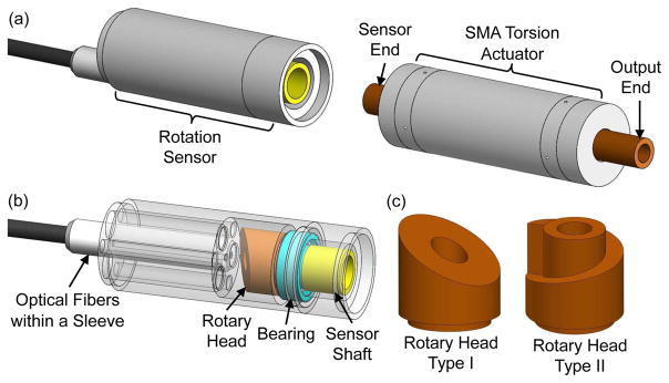
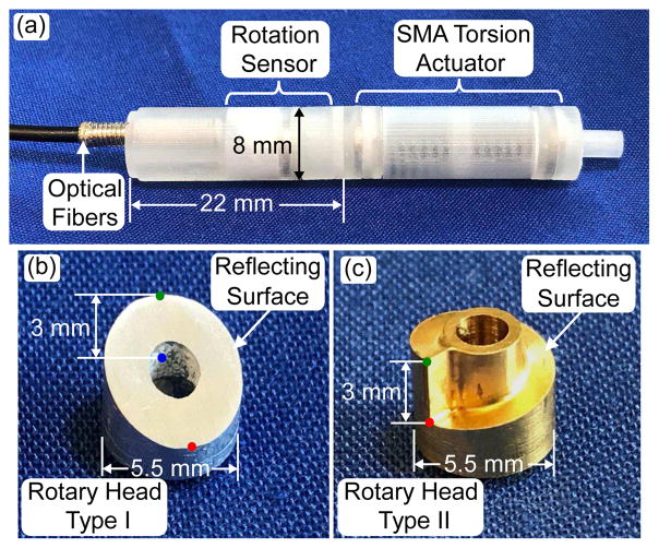
As shown in Fig. 1(a) and Fig. 2(a), the developed fiberoptic rotation sensor is primarily composed of optical fibers with a specially designed rotary head. The rotation sensor has an outer diameter of 8 mm and it is designed as a module that can be readily mounted on the SMA torsion actuator. The sensor shaft is coupled to the sensor end of the actuator shaft via friction. Within the rotation sensor, the rotary head is assembled with the sensor shaft and supported by a metallic micro bearing, as shown in Fig. 1(b). Therefore, the rotary head can rotate synchronously with the SMA torsion actuator with negligible friction load applied on the actuator. Meanwhile, the tips of the optical fibers are protected by a stainless steel sleeve with threads and installed in the bottom of the sensor through a threaded lumen. Except for the rotary head, bearing, and optical fibers, all other components are 3D printed from plastic material.
Fig. 1.
(a) 3-D model of a fiberoptic rotation sensor to be mounted on the shaft of an SMA torsion actuator. (b) Design of a fiberoptic rotation sensor including optical fibers, a rotary head, a bearing, and a shaft. (c) Two designs of the rotary head with different reflecting surface profiles.
Fig. 2.
(a) Prototype of an SMA rotary actuator integrated with a fiberoptic rotation sensor. (b) Prototype of a rotary head type I made of aluminum with a polished top surface. (c) Prototype of a rotary head type II made of brass with a polished spiral path.
One side of the rotary head facing the optical fibers is a reflecting surface with a varying profile. Thus, the distance traveled by the light beam before it reaches the reflecting surface changes when the SMA actuator rotates. Two off-the-shelf fiberoptic products (Keyence Corporation, Japan) including transmitting and receiving optical fibers and a signal conditioner with an analog voltage output from 1V to 5V have been individually employed and compared. The model FU-46 contains two receiving fibers and two transmitting fibers placed in a plus configuration and each of them has a diameter of 125 μm. The model FU-24X contains one transmitting fiber with eight surrounding fibers for receiving light and each of them has a diameter of 175 μm. Since a red LED (wavelength: 640 nm) is used as the light source, the light reflective rate is determined by the color of the rotary head and two materials including brass and aluminum are individually employed and compared.
Two types of rotary heads with different reflecting surface profiles have been designed, as shown in Figs. 1(c). The rotary head type I has a tilted and flat reflecting surface and the reflecting surface of the rotary head type II is a 1.25 mm wide one-revolution spiral path around its circumference. Figs. 2(b) and (c) show a rotary head type I made of aluminum and a rotary head type II made of brass, respectively. Both types have an outer diameter of 5.5 mm and the through hole in the center for passing surgical accessories and lead wires has a diameter of 2 mm. In Figs. 2(b) and (c), the green dot and red dot represent the highest point and lowest point on the reflecting surface, respectively. The blue dot represents the projection of the green dot on a horizontal plane passing through the red dot. The height between the highest point and lowest point is 3 mm for both rotary heads. Both of them were fabricated using a 5-axis CNC milling machine and the reflecting surface is manually polished using sandpapers and polishing compound. Although each rotation angle corresponds to a theoretically exclusive height of the reflecting surface profile for the rotary head type II, it takes more effort in fabrication and polish.
III. System Modeling
A. Rotary Head
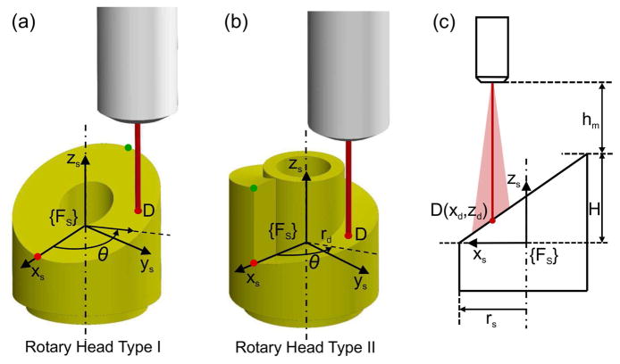
Figs. 3(a) to (c) show the schematics of optical fibers transmitting a light beam towards the rotary head type I and type II, respectively. Due to beam divergence, the red line represents the beam center with the maximum intensity. The distance traveled by the light beam before reaching the reflecting surface varies as a function of the relative rotation between the rotary head and the optical fibers. Although the employed fiberoptic sensors contain one or multiple optical fibers for transmitting or receiving light, the tip of each sensor is modeled as a transmitting fiber and a receiving fiber. The modeled transmitting fiber and receiving fiber are assumed to be coaxial, due to the compact arrangement and small diameter of the optical fibers (125 μm for model FU-46 and 175 μm for model FU-24X). As shown in Figs. 3(a) and (b), a local coordinate frame {Fs} is fixed on the rotary head. xs-axis points to the lowest position on the reflecting surface and zs-axis is aligned with the rotation axis pointing to the optical fibers. In the actual system, the clockwise rotation of the rotary head in the top view is defined as the positive motion. For the easiness of modeling, the rotation of the rotary head with respect to the fixed optical fibers is regarded as an equivalent rotation of the optical fibers about zs-axis in the opposite direction.
Fig. 3.
(a) Schematic of optical fibers transmitting a light beam towards the rotary head type I. (b) Schematic of optical fibers transmitting a light beam towards the rotary head type II. (c) Schematic of a light beam towards the reflecting point, D, on the rotary head type I in xs−zs plane.
Since the optical fibers are parallel to the rotation axis, the reflecting point, D, on the reflecting surface has a constant radius, rd, to the rotation axis. Thereby, the position of D is given by: xd = rd cos(θ) and yd = rd sin(θ), where θ is the rotation angle of the optical fibers with respect to zs-axis. The distance between the lowest position and highest position on the reflecting surface along zs-axis is denoted as H. Both rotary heads have the same radius and it is denoted as rs. Fig. 3(c) shows the schematic for the rotary head type I in xs−zs plane. Thus, the position of D along zs-axis can be derived from the geometry in Fig. 3(c), which yields:
| (1) |
For the rotary head type II, since the reflecting surface is a spiral path, the position of D along zs-axis is proportional to θ, which yields:
| (2) |
Therefore, the traveled distance by the light beam before it reaches the reflecting surface is given by:
| (3) |
where hm is the distance from the origin of {Fs} to the tip of optical fibers along zs-axis. The derivative of h with respect to θ is given by:
| (4) |
The above expression shows that the change rate of h with respect to θ is a sinusoidal curve for the rotary head type I and the change rate is small when θ is close to 0° or 180°. For the rotary head type II, the change rate of h with respect to θ is a constant, except when θ is equal to 360° (0°), the change rate of h is infinite.
B. Sensing Mechanism
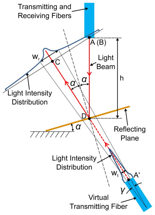
Fig. 4 shows the modulation mechanism for the light intensity collected by the receiving fiber as a function of the traveled distance by the light beam. The reflecting plane is a segment of the reflecting surface around the reflecting point. Due to the reflecting plane, the light beam is virtually transmitted by an optical fiber beneath the reflecting plane, as shown in Fig. 4. The tip centers of the transmitting fiber, receiving fiber, and virtual transmitting fiber are denoted as point A, B, and A′, respectively. Point C is a projected point to the reflected light beam from A or B. The distance from the virtual transmitting fiber to the receiving fiber along the reflective light beam is given by:
| (5) |
where α is the tilt angle of the reflecting plane and α = atan2(H, 2rs). The distance from the receiving fiber to point C is given by:
| (6) |
Fig. 4.
Modulation mechanism for the light intensity collected by the receiving optical fiber as a function of the traveled distance by the light beam.
As shown in Fig. 4, the intensity distribution of the light beam at the tip of the virtual transmitting fiber, It, is in the form of a Gaussian distribution around point A′, which yields:
| (7) |
where r is the distance to point A′, is the maximum light intensity at point A′, and wt is the Gaussian width at 1/e of the maximum intensity. The intensity distribution of the transmitted light beam remains in the form of a Gaussian distribution, with its width increasing as a nonlinear function of the distance to the tip center of the transmitting fiber [25]. Therefore, the light intensity distribution of the reflected light beam around point C is given by:
| (8) |
where Ir0 is the maximum light intensity at point C and wr is the Gaussian width at 1/e of the maximum intensity. Note that is smaller than the maximum light intensity for the transmitting fiber at point A, because the light reflective value for the reflecting surface is smaller than one. By approximating the nonlinear relationship between wr and by a conical beam profile [24], we have:
| (9) |
where γ is a divergence angle determined by the optical fibers and light source. The total light flux for a particular point along the path of the transmitted light beam, Φ, is given by [24]:
| (10) |
where I0 is the maximum light intensity at that point and w is the half width at 1/e of the maximum intensity. Since the total light flux remains as a constant along the path of the transmitted light beam, the total light flux for point A′, Φt, is equal to the total light flux for point C, Φr, which yields:
| (11) |
It is assumed that the light intensity at the cross-section of the receiving fiber is uniform due to the small diameter of the receiving fiber. Since the voltage output of the signal conditioner is proportional to the light flux received by its photo sensors via the receiving fiber, the voltage output, Us, is given by:
| (12) |
where kv is a parameter for the conversion from light flux to voltage output by photo sensors, σr is the light flux loss due to the bending of optical fibers, Ar is the cross-section area of the receiving fiber. The output sensitivity with respect to θ is given by:
| (13) |
Eqs. (4) and (13) indicate that the system sensitivity for both rotary heads can be improved by increasing H. rs and rd have no impact on the system sensitivity theoretically, but further miniaturizing the rotary head increases the fabrication difficulty. In practice, the diameter of the tip sleeve for the optical fibers determines the minimum rs and rd. Since the diameter of transmitted light beam increases as a function of the distance to point A due to beam divergence, only part of the light beam can be reflected if the width of the reflecting surface is too small, leading to a decreasing sensitivity.
IV. Experimental Studies
A. Performance Comparison
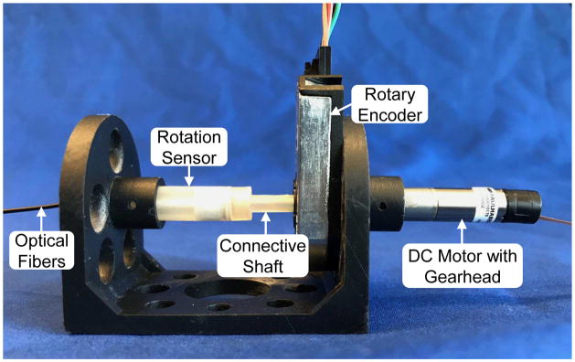
To optimize the sensor design, several experimental studies have been carried out. Fig. 5 shows the experimental setup comprised of a fiberoptic rotation sensor prototype and a DC motor with a 1024:1 gearhead (Faulhaber, Switzerland). The motor is capable of rotating the sensor shaft via a connective shaft between them. Due to the gearhead backlash, a high-resolution optical rotary encoder (CUI Inc., USA) is mounted on the connective shaft to directly measure the rotation angle. The rotation sensor is rotated back and forth stepwise for one revolution with a step size of one degree per second. The home position is set at a rotation angle where the voltage output by the fiberoptic rotation sensor is close to the minimum. A low-pass filter is employed to filter out high-frequency noise from the signal conditioner.
Fig. 5.
Experimental setup for comparing working performances of different designs and verifying the model for the fiberoptic rotation sensor.
In the first study, the performances between a rotation head type I made of brass and a rotation head type I made of aluminum were compared using the model FU-24X optical fibers. Fig. 6(a) shows that a large measurement range can be achieved by both designs, while the voltage output by the brass rotary head is higher, probably due to the higher light reflective rate of brass. The difference in the output voltage is also probably caused by the discrepancy in polishing the reflecting surface.
Fig. 6.
Experimental results for different designs: (a) Voltage output comparison between a rotary head type I made of brass and a rotary head type I made of aluminum, (b) Voltage output comparison between two different off-the-shelf fiber optic sensors, (c) Voltage output comparison between a rotary head type I made of brass and a rotary head type II made of brass.
In the second study, the performances between two models of optical fibers were compared using the rotary head type I made of brass. Fig. 6(b) shows that the model FU-24X has larger measurement range than the model FU-46. This is probably because the model FU-24X contains more receiving optical fibers, resulting in higher sensitivity than the model FU-46 when h is large. Although the rate of change of h is small when h is small for the rotary head type I, the sensitivity of optical fibers increases rapidly when the target comes closer. Hence, the voltage output oscillates around the peak when h is close to the minimum, as shown in Fig. 6(b). The choppy output is more obvious for the model FU-46, probably due to its too high sensitivity when h is small.
In the third study, the performances between a rotary head type I and a rotary head type II, both made of brass, were compared using the model FU-24X optical fibers. Fig. 6(c) shows that the voltage output for the rotary head type II has a rapid drop when the rotation angle passes 200° due to the step change in the spiral path. The voltage output by the rotary head type II is less smooth, probably due to the difficulty in polishing its spiral path. Its voltage output is also higher, probably due to the light reflection by other surfaces besides the spiral path.
Thus, the combination of a rotary head type I made of brass and the model FU-24X optical fibers is the optimal choice for a fiberoptic rotation sensor. Note that three individual tests were conducted in each study. Fig. 6(c) shows good uniformity among different tests and negligible hysteresis between positive motion and negative motion is observed. A supplementary study was carried out by measuring the voltage output in 60 s when the rotation angle was fixed. It was observed that the output signal has an average fluctuation of 1.9 mV, 1.7 mV, and 2.2 mV with negligible drift over time when the rotation angle is 0°, 90°, and 180°, respectively. In each test, a black vinyl tape was wrapped outside the rotation sensor after 30 s to mimic the illumination when the rotation sensor is used in in vivo studies. It was observed that the output voltage was barely affected by the change of environmental illumination.
B. Model Verification
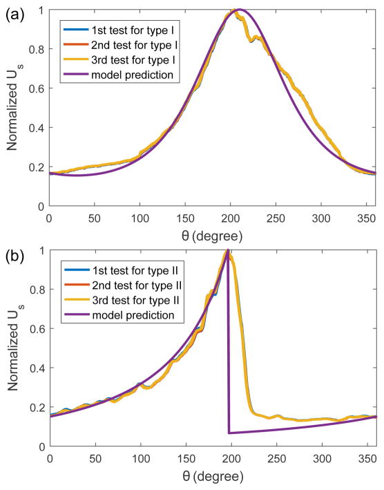
To verify the derived model for the fiberoptic rotation sensor, the least-squares approach is employed to fit the derived model with experimental data. According to the model equations in Section III, several parameters need to be determined. The geometric parameters, such as hm, H, rd and rs, are obtained from the sensor design. The fiberoptic parameter, γ, is obtained from the specification sheet of the optical fibers. The value of wt is found to have a negligible effect on the voltage output since it is much smaller than the second item in Eq. (9). By normalizing Eq. (12) and the experimental data, characterization of other parameters including kv, σr, Ar, and is not required for model verification.
During the implementation of the least-squares approach, the home position is searched to achieve the best fitting result. By individually fitting the normalized model with the normalized experimental data for the rotary head type I and type II, the results are shown in Figs. 7(a) and (b), respectively. The root-mean-square (RMS) errors for the rotary head type I made of brass and the rotary head type II made of brass are 0.04 and 0.17, respectively, and the R-squared values for them are 0.98 and 0.54, respectively. Therefore, the derived model has successfully modeled the response of a fiberoptic rotation sensor composed of the rotary head type I. Although there is a relatively large discrepancy between model prediction and experimental data for the rotary head type II, the model has captured the major response of the developed sensor. The discrepancy is primarily caused by the following factors: a) less polished reflecting surface, b) unmodeled light reflection by surfaces besides the spiral path, and c) unmodeled transition of the diverged light beam from the highest position to the lowest position on the spiral path.
Fig. 7.
Normalized experimental data and model prediction for the fiberoptic rotation sensor when the sensor shaft is rotated by 360°: (a) RMS error is 0.04 and R-squared value is 0.98 for the rotary head type I made of brass and (b) RMS error is 0.17 and R-squared value is 0.54 for the rotary head type II made of brass.
C. Calibration and Control Test
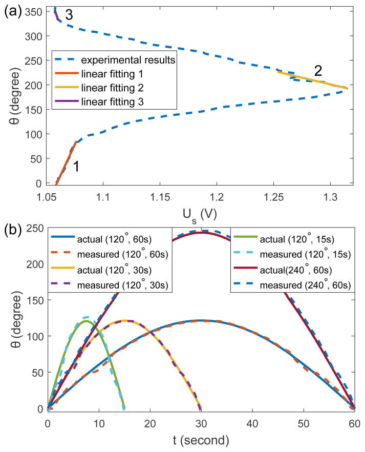
Based on the above studies, a fiberoptic rotation sensor composed of a rotary head type I made of brass and the model FU-24X optical fibers has been developed for the SMA torsion actuator. The experimental data for the rotary head type I in Fig. 6(c) is employed to calibrate the mapping from voltage output to rotation angle. The experimental data for the negative motion is linearly interpolated at the rotation angle for the positive rotation. As a result, the dashed line in Fig. 8(a) shows the average between interpolated results and the experimental data for the positive motion. Regions 1 and 3 and region 2 in Fig. 8(a), corresponding to the basin and peak in Fig. 6(c), respectively, do not have a strict one-to-one mapping from voltage output to rotation angle, so linear fitting is applied to them individually. For the remaining regions, a look-up table is made based on the experimental data and the rotation angle for a voltage output between two sampled data points is computed by linear interpolation.
Fig. 8.
(a) Calibration results for the fiberoptic rotation sensor. R-squared values for the linear fitting 1, 2, and 3 are 0.98, 0.88, and 0.55, respectively. (b) Comparison between the measurements by the rotary encoder and the developed fiberoptic rotation sensor. RMS errors are 2.27°, 2.06°, 4.36°, and 5.99° for the tests when (As, Ts) is equal to (120°, 120 s), (120°, 60 s), (120°, 30 s), and (240°, 120 s), respectively.
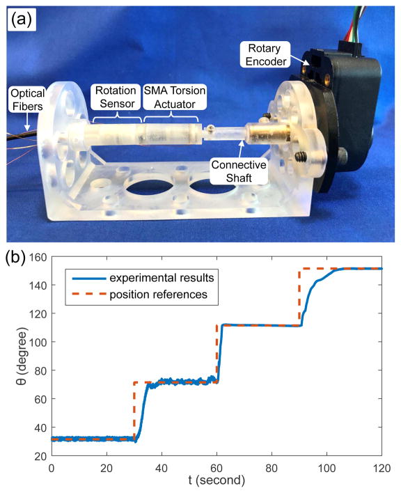
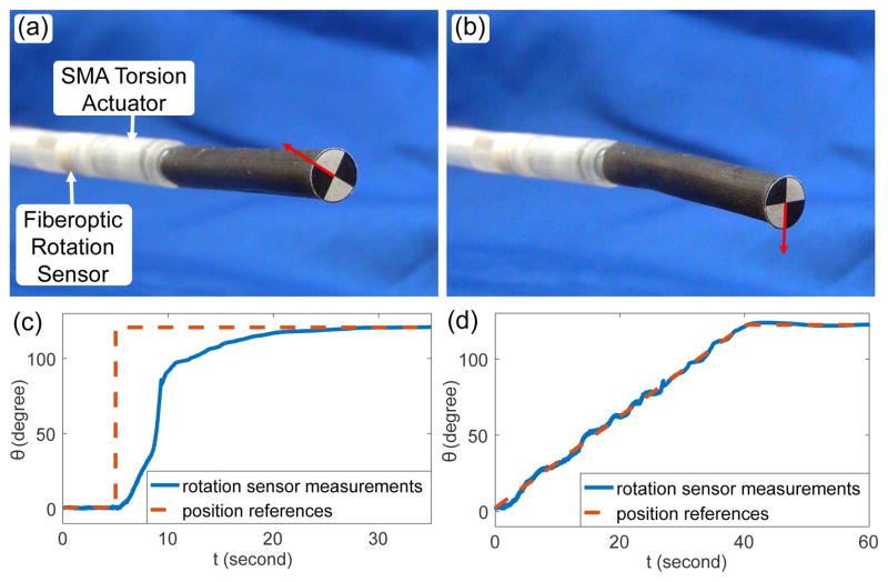
To evaluate the working performance of the developed fiberoptic rotation sensor, the sensor is actuated by the DC motor to follow sinusoidal profiles with different amplitude, As, and periodic time, Ts, using the setup shown in Fig. 5. The comparison between the measurements by the fiberoptic rotation sensor and the rotary encoder is shown in Fig. 8(b). It is observed that the measurement becomes less precise when the rotation speed is increased and Ts is reduced to 30 s, probably due to the slight decentration of the rotary head at high rotary speed. When As is increased to 240°, more than one possible rotation angle exists for a particular voltage output, so the timing of employing the linear fitting results for region 2 is assumed to be pre-known based on the commands to the DC motor. The measurement error further increases when As is equal to 240°, due to the error in the linear fitting for region 2. To evaluate the capability of the developed fiberoptic rotation sensor in controlling the SMA torsion actuator, an experimental setup was developed as shown in Fig. 9(a). The fiberoptic rotation sensor is mounted on the SMA torsion actuator using super glue with the sensor end of the actuator shaft coupled to the sensor shaft via friction. After fixing the actuator with the rotation sensor on the setup using screws, the output end of the actuator shaft is connected to a rotary encoder (US Digital®, USA) via a connective shaft using screws. Stepwise position references were designed with a step time of 30s and a step size of 40° for three steps. A PI controller was developed based on the feedback of fiberoptic rotation sensor to selectively heat one of the SMA springs for positive rotation. The PI controller calculates the required magnitude of the heating current and the current magnitude is converted to the PWM intensity of the voltage input to a MOSFET (International Rectifier, USA) that controls the the heating current. Fig. 9(b) shows the comparison between the designed references and the measurements by the rotary encoder. It shows that the SMA torsion actuator can depend on the fiberoptic rotation sensor to achieve relatively precise tracking with a steady-state error of 0.21°. In addition, a robot for neurosurgical intracerebral hemorrhage evacuation (NICHE) [15] has been developed by integrating a fiberoptic rotation sensor with the SMA torsion joint for proof-of-concept demonstrations. Figs. 10(a) and (b) show the rotation of the torsion joint for a 120° step input under a PI controller. Fig. 10(c) shows the measurements by the fiberoptic rotation sensor and the steady-state error is 0.16° at 35 s. A similar demonstration was performed with linear position references. As shown in Fig. 10(d), the average tracking error is 1.27° and the steady-state error is 0.19° at 60 s. Although the actual tracking error is probably larger than the error measured by the fiberoptic rotation sensor due to the measurement error, the SMA torsion joint of the NICHE robot shows good performance in tracking static position references, as shown in Figs. 9 and 10.
Fig. 9.
(a) Experimental setup for evaluating the control performance of the SMA torsion actuator integrated with the fiberoptic rotation sensor. (b) Comparison between the experimental results and stepwise references for the SMA torsion actuator.
Fig. 10.
(a–b) Initial (a) and final (b) configuration for 120° rotation of the torsion joint for a step input. (c) Measurements by the fiberoptic rotation sensor for a step input. (d) Measurements by the fiberoptic rotation sensor for linear position references.
V. Discussion and Conclusions
In this paper, we have presented the development of a fiberoptic rotation sensor for an SMA torsion actuator used for neurosurgical applications. The fiberoptic rotation sensor is comprised of optical fibers, a signal conditioner, a rotary head, a bearing, and a shaft to connect with the actuator shaft. The mechanism of light intensity modulation by the rotary head has been modeled and the model was experimentally verified. To optimize the sensor design, the working performances of different designs were compared. Based on the calibration results, the developed fiberoptic rotation sensor can precisely measure rotary motion and an SMA torsion actuator can be controlled with feedback from the fiberoptic rotation sensor. For the future work, we are planning to implement multiple fiber optic sensors for the improvement of measurement precision and range. A neurosurgical robot integrated with the fiberoptic rotation sensor will be tested in an ex-vivo environment.
Acknowledgments
Research reported in this publication was supported in part by the National Institute of Biomedical Imaging and Bioengineering of the National Institutes of Health under Award Number R21EB018581. The content is solely the responsibility of the authors and does not necessarily represent the official views of the National Institutes of Health.
References
- 1.Ho M, McMillan AB, Simard JM, Gullapalli R, Desai JP. Toward a meso-scale SMA-actuated MRI-compatible neurosurgical robot. IEEE Transactions on Robotics. 2012;28(1):213–222. doi: 10.1109/TRO.2011.2165371. [DOI] [PMC free article] [PubMed] [Google Scholar]
- 2.Ho M, Kim Y, Cheng SS, Gullapalli R, Desai JP. Design, development, and evaluation of an MRI-guided SMA spring-actuated neurosurgical robot. The International journal of robotics research. 2015;34(8):1147–1163. doi: 10.1177/0278364915579069. [DOI] [PMC free article] [PubMed] [Google Scholar]
- 3.Kim Y, Cheng SS, Diakite M, Gullapalli RP, Simard JM, Desai JP. Toward the development of a flexible mesoscale MRI-compatible neurosurgical continuum robot. IEEE Transactions on Robotics. 2017 doi: 10.1109/TRO.2017.2719035. [DOI] [PMC free article] [PubMed] [Google Scholar]
- 4.Ayvali E, Liang C-P, Ho M, Chen Y, Desai JP. Towards a discretely actuated steerable cannula for diagnostic and therapeutic procedures. The International journal of robotics research. 2012;31(5):588–603. doi: 10.1177/0278364912442429. [DOI] [PMC free article] [PubMed] [Google Scholar]
- 5.Ayvali E, Desai JP. Accurate in-plane and out-of-plane ultrasound-based tracking of the discretely actuated steerable cannula. Robotics and Automation (ICRA), 2014 IEEE International Conference on; IEEE; 2014. pp. 5896–5901. [Google Scholar]
- 6.Kim Y, Desai JP. Design and kinematic analysis of a neurosurgical spring-based continuum robot using SMA spring actuators. Intelligent Robots and Systems (IROS), 2015 IEEE/RSJ International Conference on; IEEE; 2015. pp. 1428–1433. [Google Scholar]
- 7.Shi C, Luo X, Qi P, Li T, Song S, Najdovski Z, Ren H, Fukuda T. Shape sensing techniques for continuum robots in minimally invasive surgery: A survey. IEEE Transactions on Biomedical Engineering. 2016 doi: 10.1109/TBME.2016.2622361. [DOI] [PubMed] [Google Scholar]
- 8.Miyashita K, Takahashi T, Yamanaka M. Features of a magnetic rotary encoder. IEEE Transactions on Magnetics. 1987;23(5):2182–2184. [Google Scholar]
- 9.Tresanchez M, Palleja T, Teixidó M, Palacin J. Using the image acquisition capabilities of the optical mouse sensor to build an absolute rotary encoder. Sensors and Actuators A: Physical. 2010;157(1):161–167. [Google Scholar]
- 10.Bajić JS, Stupar DZ, Dakić BM, Živanov MB, Nagy LF. An absolute rotary position sensor based on cylindrical coordinate color space transformation. Sensors and Actuators A: Physical. 2014;213:27–34. [Google Scholar]
- 11.Haberli A, Schneider M, Malcovati P, Castagnetti R, Maloberti F, Baltes H. Two-dimensional magnetic microsensor with on-chip signal processing for contactless angle measurement. IEEE Journal of Solid-State Circuits. 1996;31(12):1902–1907. [Google Scholar]
- 12.Nakano K, Takahashi T, Kawahito S. A CMOS rotary encoder using magnetic sensor arrays. IEEE Sensors Journal. 2005;5(5):889–894. [Google Scholar]
- 13.Kennel R, et al. New developments in capacitive encoders for servo drives. Power Electronics, Electrical Drives, Automation and Motion, 2008. SPEEDAM 2008. International Symposium on; IEEE; 2008. pp. 190–195. [Google Scholar]
- 14.Zheng D, Zhang S, Wang S, Hu C, Zhao X. A capacitive rotary encoder based on quadrature modulation and demodulation. IEEE Transactions on Instrumentation and Measurement. 2015;64(1):143–153. [Google Scholar]
- 15.Sheng J, Gandhi D, Gullapalli R, Simard JM, Desai JP. Development of a meso-scale SMA-based torsion actuator for image-guided procedures. IEEE Transactions on Robotics. 2016 doi: 10.1109/TRO.2016.2623348. [DOI] [PMC free article] [PubMed] [Google Scholar]
- 16.Sheng J, Desai JP. Design, modeling and characterization of a novel meso-scale SMA-actuated torsion actuator. Smart Materials and Structures. 2015;24(10):105005. doi: 10.1088/0964-1726/24/10/105005. [DOI] [PMC free article] [PubMed] [Google Scholar]
- 17.Sheng J, Desai JP. A novel meso-scale SMA-actuated torsion actuator. Intelligent Robots and Systems (IROS), 2015 IEEE/RSJ International Conference on; IEEE; 2015. pp. 4718–4723. [Google Scholar]
- 18.Park K, Desai JP. Micropositioning and control of an underactuated platform for microscopic applications. IEEE/ASME Transactions on Mechatronics. 2016;21(6):2635–2646. doi: 10.1109/TMECH.2016.2579620. [DOI] [PMC free article] [PubMed] [Google Scholar]
- 19.Gassert R, Moser R, Burdet E, Bleuler H. MRI/fMRI-compatible robotic system with force feedback for interaction with human motion. IEEE/ASME transactions on mechatronics. 2006;11(2):216–224. [Google Scholar]
- 20.Puangmali P, Liu H, Althoefer K, Seneviratne LD. Optical fiber sensor for soft tissue investigation during minimally invasive surgery. Robotics and Automation, 2008. ICRA 2008. IEEE International Conference on; IEEE; 2008. pp. 2934–2939. [Google Scholar]
- 21.Puangmali P, Althoefer K, Seneviratne LD. Novel design of a 3-axis optical fiber force sensor for applications in magnetic resonance environments. Robotics and Automation, 2009. ICRA’09. IEEE International Conference on; IEEE; 2009. pp. 3682–3687. [Google Scholar]
- 22.Tan UX, Yang B, Gullapalli R, Desai JP. Triaxial MRI-compatible fiber-optic force sensor. IEEE Transactions on Robotics. 2011;27(1):65–74. doi: 10.1109/TRO.2010.2090061. [DOI] [PMC free article] [PubMed] [Google Scholar]
- 23.Hirose S, Yoneda K. Development of optical six-axial force sensor and its signal calibration considering nonlinear interference. Robotics and Automation, 1990. Proceedings., 1990 IEEE International Conference on; IEEE; 1990. pp. 46–53. [Google Scholar]
- 24.Puangmali P, Althoefer K, Seneviratne LD. Mathematical modeling of intensity-modulated bent-tip optical fiber displacement sensors. IEEE Transactions on Instrumentation and Measurement. 2010;59(2):283–291. [Google Scholar]
- 25.Faria JB. A theoretical analysis of the bifurcated fiber bundle displacement sensor. IEEE Transactions on Instrumentation and Measurement. 1998;47(3):742–747. [Google Scholar]


