Significance
Diamond anvil cell (DAC) could be one of the most popular and versatile devices to generate static high pressure. By using beveled anvils, researchers can study materials up to 4 Mbar, which is considered as a limit pressure of conventional DAC; however, very few experiments have visited this pressure region. Here, we have systematically studied the behaviors of three DACs with three typical culet sizes, one of which reached 4 Mbar. In addition, by using submicrometer synchrotron X-ray probe, double cupping of beveled diamond anvils up to 4 Mbar is reported experimentally. Our results provide important guidance for future DAC studies to extreme high pressures.
Keywords: high pressure, diamond anvil cell, deformation
Abstract
The diamond anvil cell (DAC) is considered one of the dominant devices to generate ultrahigh static pressure. The development of the DAC technique has enabled researchers to explore rich high-pressure science in the multimegabar pressure range. Here, we investigated the behavior of the DAC up to 400 GPa, which is the accepted pressure limit of a conventional DAC. By using a submicrometer synchrotron X-ray beam, double cuppings of the beveled diamond anvils were observed experimentally. Details of pressure loading, distribution, gasket-thickness variation, and diamond anvil deformation were studied to understand the generation of ultrahigh pressures, which may improve the conventional DAC techniques.
The diamond anvil cell (DAC) was invented almost 60 y ago (1). It squeezes samples in between two opposing diamonds to generate extremely high static pressure above 100 GPa (2). Many high-pressure DAC techniques have been developed to make it possible to generate pressures up to 400 GPa (3), such as the usage of a gasket, a beveled anvil design (4), different types of seat (5), etc. This makes the DAC a very important tool not only in geoscience, where it is used to study the earth’s interior across the whole pressure range to the inner core ∼360 GPa, but also for exploring the novel phenomena of matter with extremely high density in multidisciplinary scientific fields such as physics (6–8), chemistry (9–12), material science (13, 14), and even bioscience (15). Recently, an innovative use of a DAC with a pair of secondary nanodiamond anvils was reported to achieve above 6 Mbar (16, 17). However, its technical challenge and difficult sample preparation have limited its application as a routine way of generating high pressures.
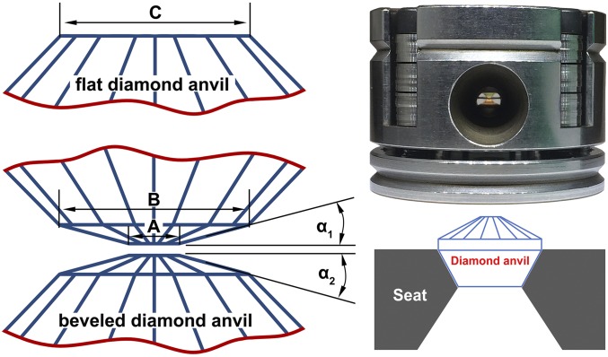
In conventional DAC experiments, typically flat and beveled diamond anvils (Fig. 1, Left) are used to generate high pressures. For megabar pressure experiments (>100 GPa), beveled diamond anvils with small culets are usually recommended in practice. Many factors can cause the failure of diamond anvils, such as the DAC alignment, DAC stability, anvil quality, gasket selection, etc. Addressing all of these factors makes it challenging to achieve pressures above 300 GPa. Moreover, under a very high load, the beveled anvil will “cup” (bend outward), causing one of the major limitations on the achievable pressure for a beveled DAC (18). Thus, understanding the behavior of a DAC under very high pressures, including the process of pressure loading, the evolution of diamond anvil elastic deformation, gasket flow, and pressure distribution along the culet area, is indispensable for further understanding and developing the DAC technique.
Fig. 1.
Flat and beveled anvils (Left), a symmetric DAC (Upper Right) and Boehler-type seat (Lower Right). (Left) Sizes of a beveled (A and B) and a flat culets (C) are indicated.
Some previous experimental studies explored the behavior of the DAC under high pressures (18, 19). However, detailed local strain stress information (e.g., on the small culet area) could not be derived due to the limitation of the probe size, which typically has a 5 ∼ 10-μm spatial resolution. A few finite-element modeling studies also analyzed the anvil deformation (20, 21) and its stress state (21–23) under high pressures. For a beveled diamond anvil geometry, the finite-element modeling unveiled double cupping in the center flat and beveled areas at 300 GPa (21). However, this double cupping has not been observed experimentally at high pressures up to 300 GPa. The experimental and theoretical discrepancy is likely due to either a low spatial resolution or not achieving high enough pressure in the experiments (18).
In this paper, by using submicrometer focused synchrotron X-ray beam, we performed in situ high-pressure synchrotron X-ray diffraction and absorption experiments to investigate the behavior of the DAC up to 400 GPa. The submicrometer X-ray offers many advantages in high-pressure research (24, 25), especially when dealing with small samples, because its high spatial resolution makes it possible to resolve details within a tiny culet area.
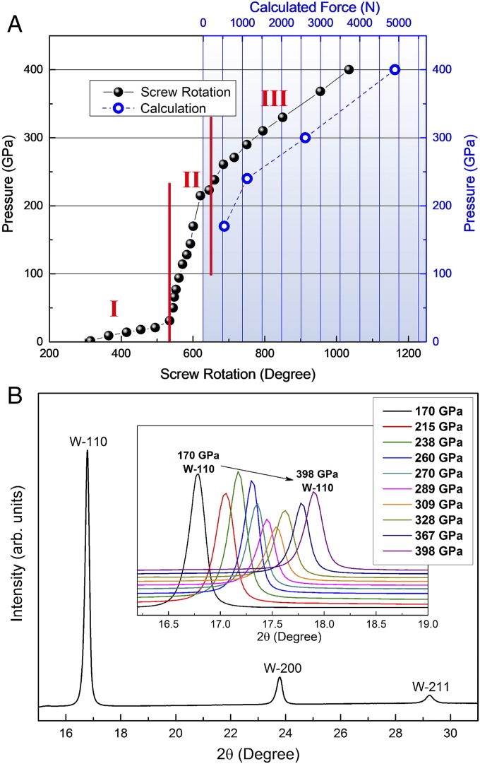
Mao-type symmetric DACs with culets of 20 µm beveled to 250 or 200 µm with a beveled angle of 8.5° on Boehler-type seats (Fig. 1, Right) were used to achieve 400-GPa pressure. To simplify the study, an initial thickness of 250-μm tungsten (W) foil was used as both the sample and gasket. Pressure was applied by tightening the screws, thus bending the spring washers and then applying a force proportional to the angles of the screw rotation. The central pressure as a function of the screw rotation was recorded in Fig. 2A (solid dots). This pressure-loading curve is nonlinear and can be divided into three sections with different loading rates. We will discuss the loading curve in detail later. Fig. 2B presents a typical X-ray diffraction (XRD) pattern of W with a pressure of 170 GPa at the center of the culet. The insert shows the W-(110) peak shift during compression, which indicates a pressure increase from 170 to 398 GPa.
Fig. 2.
Pressure–load curve (A) and in situ XRD patterns of W at different pressures (B). The solid dots and open circles in A represent the experimental and calculation values, respectively.
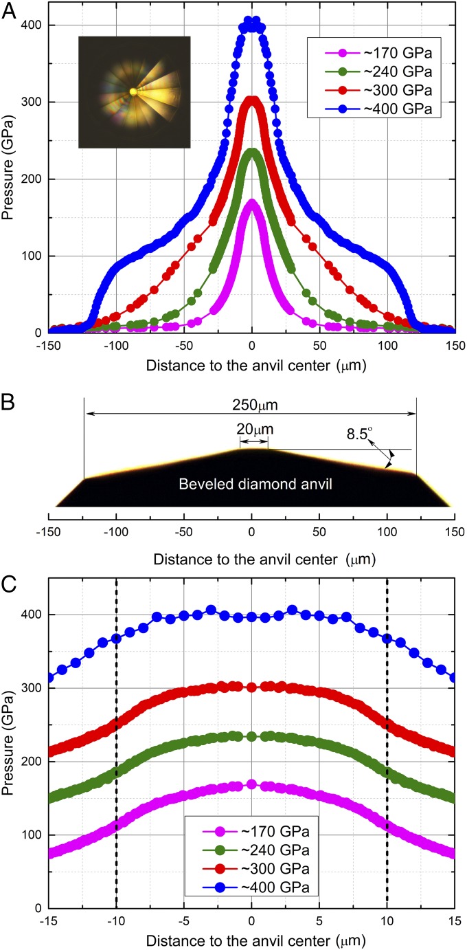
The pressure distribution as a function of the radial distance across the culet is shown in Fig. 3 A and C at four selected center pressures of ∼170, ∼240, ∼300, and ∼400 GPa, respectively. A schematic of the 20-µm beveled to 250-µm anvil is shown in Fig. 3B as a reference. In this study, the diamond anvils failed during the 2D XRD mapping at a center pressure of ∼400 GPa. Thus, only 1D XRD line-scan (1-μm step size) data were used to provide the pressure distribution at that pressure point, and subsequently fewer data points were obtained (Fig. 3 A and C, Top) compared with the 2D scans at lower pressures (see Methods for details). The results indicate that the pressure distribution was more concentrated on the culet area (<20 μm in diameter) at each pressure point, which agrees with previous results (18) and proves the basic premise of the bevel design to improve the achievable pressure.
Fig. 3.
Pressure distributions in a beveled DAC. Pressure distributions as a function of the radial distance from the center of the culet at four center pressures of ∼170, ∼240, ∼300, and ∼400 GPa, respectively. (A) Large region and (C) culet region. B is a side view of the diamond anvil with a 20-μm culet beveled to 250 μm at 8.5° as a reference. The photomicrograph in A shows the reflectance in a visual observation of the tiny culet and beveled area at ∼400 GPa.
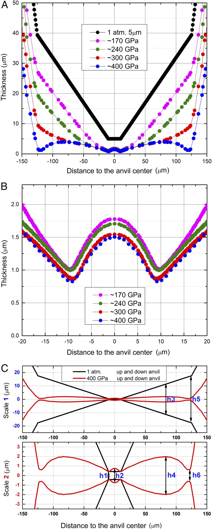
Fig. 4 A and B shows variations of gasket thickness as a function of the radial distance across the culet in different scales. Four thickness variation curves are shown for the same center pressures as those in Fig. 3: ∼170, ∼240, ∼300, and ∼400 GPa, respectively. A profile with an initial central thickness of 5 μm on the 20-μm flat culet area is shown in Fig. 4A for comparison. In general, the W gasket became thinner during loading. However, as the loading increased, the gasket thinning in the culet area (radius from 0 to 10 μm) plateaued at ∼170 GPa, whereas the thinning continued in the beveled area (radius from 10 to 125 μm) up to ∼400 GPa.
Fig. 4.
W gasket-thickness distribution at various pressures and anvil shapes compared between 1 atm and ∼400 GPa. Thickness distribution as a function of the radial distance from the center of the culet at four center pressures of ∼170, ∼240, ∼300, and ∼400 GPa, respectively. (A) Large region and (B) culet region. (C) Comparison of the anvil shapes between ambient pressure (black) and at ∼400 GPa (red) in different scales, large (C, Upper) and small (C, Lower).
Deformation of the diamond anvils can be inferred from changes in the W gasket thickness. Fig. 4C shows the anvil shape comparison between 1 atm and ∼400 GPa. The upper and lower panels in Fig. 4C are shown in a different scale on the vertical axis, giving a full view and detailed shape of the culets at 1 atm and ∼400 GPa, respectively. Initially, at 1 atm, the culet (<20 μm in diameter) and the beveled area (between 20 and 250 μm in diameter) are flat with h3 = 22.9 μm at a diameter of 160 μm and h5 = 35.2 μm at the outer edge. Upon compression, the surface of the central culet becomes concave with h1 = 0.8 μm at the edge and h2 = 1.5 μm at the center under ∼400 GPa (Fig. 4C). Likewise, the beveled area becomes concave at ∼400 GPa with h1 = 0.8 μm at the inner edge (diameter = 20 μm), h4 = 4.0 μm, and h6 = 1.2 μm at the outer edge (diameter = 250 μm). A similar shape is also observed at pressures of ∼170, ∼240, and ∼300 GPa. These observations indicate that double cupping occurs on the beveled anvil surfaces at 170 GPa or possibly even lower pressure. The reason that the cupping was only observed on the beveled area and not the small center flat area in a previous experimental study (18) is certainly due to the lower spatial resolution of the larger probing X-ray beam size used.
With the pressure distribution data in hand, forces on whole culet area can be estimated. Here we estimate the forces assuming the measured pressure from XRD is the normal stress on the culet, which is certainly not the case in the real condition; however, considering the complicated real condition caused by cupping in addition to the few differences between the normal and the radial stress, the force calculated using the pressure from the XRD could be a good estimation. Table 1 lists the forces on the 250- and 20-μm culet area and the average pressure, assuming the pressure is homogeneous on the whole 250-μm area at the four center pressures. At the highest load of ∼400 GPa, the force on the culet area is 4,901 N, which is almost a half-ton force on the diamond anvils with an average pressure of 100 GPa. However, when the central pressure is ∼170 GPa, the average pressure is only 11 GPa, indicating that at high loads, the cupping of the diamond anvils helps to redistribute the pressure and reduce the pressure concentration on the small culet area. Table 1 shows the reduction in the center/average pressure ratio number from 15 to 4. The calculated forces on the whole culet area at different center pressures have also been plotted in Fig. 2A as four open circles, showing that they follow the same trend as the real experiment.
Table 1.
Forces and average pressures at four different center pressures
| Center pressure, GPa | Force on 250-μm culet, N | Force on 20-μm culet, N | Average pressure, GPa | Ratio of center/average pressure |
| 170 | 540 | 45 | 11 | 15 |
| 240 | 1,126 | 67 | 23 | 10 |
| 300 | 2,612 | 89 | 53 | 6 |
| 400 | 4,901 | 122 | 100 | 4 |
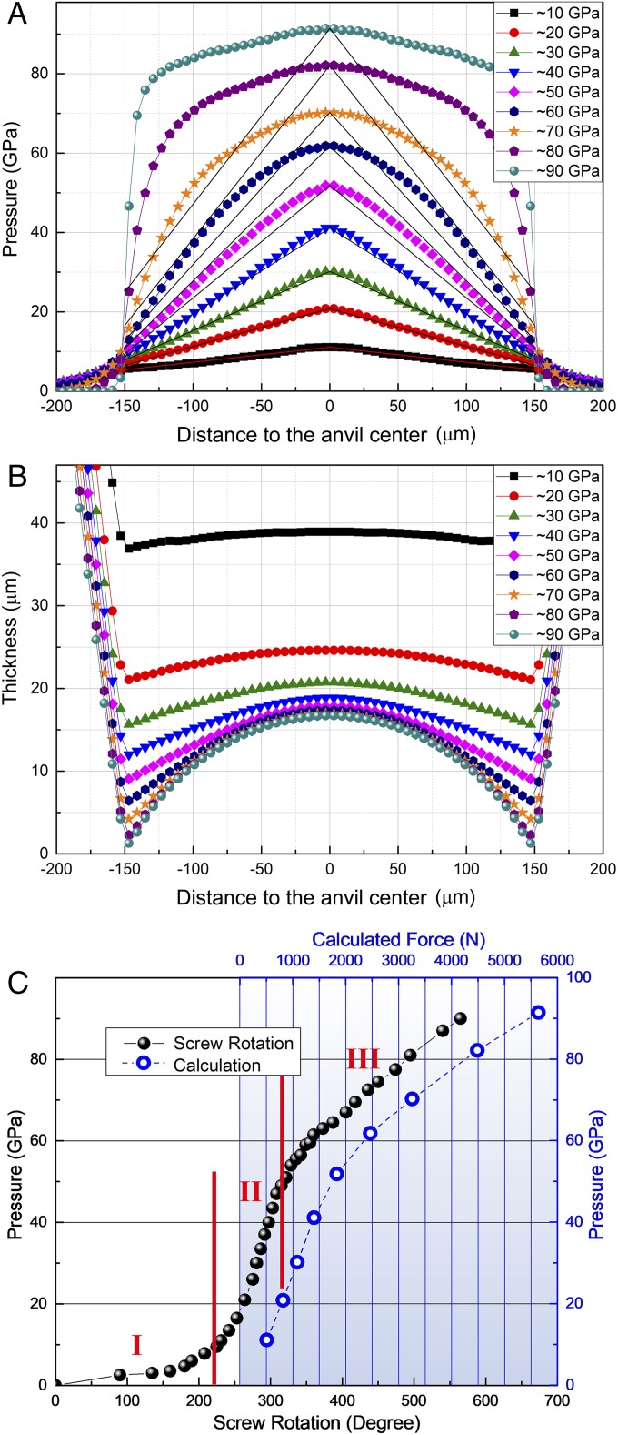
Since most DAC experiments are under 100 GPa, after the study with 20-µm beveled to 250-μm culets we also performed an experiment with flat 300-μm culets to investigate their behavior up to ∼90 GPa. In this experiment, a 1 × 2-μm focused X-ray beam was used as the probe. Fig. 5A shows the evolution of the pressure distributions at elevated center pressures. Straight lines connecting the peak pressures at the center and edge pressures at ±150 μm are presented as references for each center pressure. At center pressures below ∼40 GPa, the pressure distribution is more or less linear from the center to the edge. However, when pressure is increased to above ∼50 GPa, deviations from the linear pressure distribution appear and become increasingly severe up to ∼90 GPa (the highest pressure in this study). A linear pressure distribution has been observed in many previous studies and is used to estimate the maximum shear stress (26) using the equation dP/dr ∼ 2τ/h, where P is the pressure, r is the radius from the culet center, τ is the maximum shear stress, and h is the thickness of the sample. However, estimations using this method are inapplicable when pressure deviates significantly from a linear distribution. Fig. 5B shows the gasket-thickness variations as the pressure increases, from which anvil deformation can be inferred. First, the anvil cupping begins at very low pressure, although the bending of the culet surface is very slight. Second, the gasket thickness at the center does not change much after ∼50 GPa, where the cupping becomes increasingly severe.
Fig. 5.
The behavior of a flat 300-µm-anvil DAC up to 90 GPa. Pressure distributions (A) and gasket-thickness variations (B) as a function of the radial distance from the center of the culet at different center pressures. (C) The pressure load curves, solid dots, and open circles are from the experiment and calculations, respectively.
Fig. 5C shows the center pressure as a function of screw rotation, which is proportional to the loading force. The zero-angle positions from the experiments in both Figs. 2A and 5C were set where the screws were finger tight, then the angle of the screw rotation and the center pressure were recorded when DACs were loaded. The loading curve can be divided into three stages with two intersectional points at about 10 and 50 GPa. In stage I, pressure increased slowly with plastic deformation of the W gasket; in this stage, the gasket flows significantly to release the force accumulated on the culet with a slow pressure increase. In stage II, when a linear pressure distribution has been established from ∼10 to ∼50 GPa, the gasket becomes “locked” and is gradually flattened with a rapid center pressure increase. Finally, in stage III above ∼50 GPa, pressures are redistributed, and total “cupping” presents. In this stage, a portion of the force has to be used to help pressure redistribute and not only work to increase the peak pressure in the center. Thus, the loading rate is reduced more slowly than in stage II.
The forces on the culet area can also be calculated like those in Fig. 2A with different pressure distributions at each center pressure. Fig. 5C shows the center pressure as a function of calculated forces on the 300-μm culet (open circles). The curve from the calculation matches stages II and III very well, which confirms that the loading-rate changes are the result of pressure redistribution between stages II and III. The calculated forces on the culet area in Figs. 2A and 5C are part of the forces totally applied to the DACs. In real experiment, there are many other forces such as the one applying on the pavilion part due to the gasket extruding out of the culet, the one to bend the DAC itself, the one against frictions during load, etc. However, the force on the culet area is a major contribution of the applied force to the DAC, especially when the DAC is under relatively high pressures.
The pressure-load curve with 300-μm flat culets has the same “s” shape as the one using 20-μm beveled to 250-μm culets. The s-shaped curve in the 400-GPa experiment (Fig. 2A) has the same features: a slower loading rate in stages I and III than in stage II, which is caused by gasket plastic deformation and pressure redistribution, respectively. A similar experiment on 100-µm-beveled to 300-μm-beveled culets was also performed up to 175 GPa, and an s-shaped curve was also observed (Fig. S1). This s-shape loading behavior is universal in all conventional DAC experiments.
In summary, we studied the behaviors of conventional DACs up to 400 GPa using a submicrometer X-ray beam. The relationship between the s-shaped load curve, pressure distribution, gasket thickness variation, and anvil deformation on both the beveled and flat anvils were investigated in detail. This study shows that an s-shaped loading behavior and unavoidable cupping in both beveled and flat anvils are universal in conventional DAC experiments. In addition, double cupping up to 400 GPa was observed experimentally both in a small culet area and the whole beveled-anvil area. The small culet area first cups and then remains roughly the same up to the highest load, while the whole beveled-anvil area experiences continuous cupping. To exceed the pressure limit of a conventional DAC, using a superhard nanocrystalline diamond (27, 28) up to the anvil material could be a solution (29).
Methods
High pressures were generated using Mao-type symmetric DACs with Boehler-type seats. Beveled anvils with culet size of 20 µm beveled to 250 or 200 µm; 100 µm beveled to 300 µm with all beveled angle of 8.5°; and flat anvils with culet size of 300 µm were used to achieve ∼400-, ∼175-, and ∼90-GPa pressures, respectively. All of the experiments were performed at room temperature.
In situ high-pressure XRD was carried out to monitor the pressure changes and distribution on both the culet and beveled areas at beamlines 34-ID-E, 2-ID-D, and 16-ID-B of the Advanced Photon Source, Argonne National Laboratory, and the BL15U1 beamline, Shanghai Synchrotron Radiation Facility in China. Diffraction patterns were recorded using Mar-CCD or Pilatus area detectors. The X-ray beam sizes at 34-ID-E, 2-ID-D, 16-ID-B, and BL15U1 were ∼500 nm, ∼250 nm, 1 × 2 µm, and 2 × 2 µm, respectively.
To measure the gasket thickness, in situ high-pressure X-ray absorption profiles were measured at beamlines 34-ID-E and 16-ID-B. According to absorption law, the equation I/I0 = exp(−μρd) was used to calculate the thickness of the W gasket, where I, I0, μ, ρ, and d represent the X-ray intensity after the sample, incident X-ray intensity before the sample, mass attenuation coefficient, density, and thickness of the sample (W), respectively. The density of W was derived from its equation of state (30) using the XRD data. The mass attenuation coefficient of W was obtained from National Institute of Standards and Technology (31). A normalized transmission intensity through the empty DAC without the W gasket was used as I0 in this study; and the normalized transmission intensity through the W gasket and DAC was used as I. For the 400-GPa experiment, two X-ray energies of 14 and 21 keV were selected to optimize the contrast of the absorption measurement considering the comparison between the thickness and the absorption length of the W gasket. Typically, at low pressures when the gasket was thicker, a 21-keV X-ray was used; for a culet area where the gasket was thin, a 14-keV X-ray was always used. A 30.5-keV X-ray was used for the experiments to ∼175 and ∼90 GPa.
For both the XRD and X-ray absorption measurement in the 400-GPa experiment, typically a 2D X-ray absorption mapping (∼1-h scanning time) was first measured after the pressure was increased to the target pressure, and then a 2D XRD mapping (∼5-h scanning time) was performed. The 2D mappings were performed at selected pressures to cover the whole culet area with two different step sizes: (i) Large-area scan: step size 20 μm, coverage 320 × 320 μm2. (ii) Small-area scan: step size 1 μm, coverage 40 × 40 μm2. Both mappings were centered on the culet center. Circular symmetry was assumed for the 2D maps, and the data were converted into radial 1D data for averaging (Fig. S2A). One-dimensional XRD scan on culet of 20 μm beveled to 200 μm was performed to get the pressure distribution at the center pressure of ∼400 GPa. Pressure distribution on 20 μm beveled to 200 μm was then converted to that of 20 μm beveled to 250-μm culet. The 20-μm area was kept the same but the beveled part from 20 to 200 μm was scaled up to 250 μm. For the experiments to ∼175 and ∼90 GPa, 1D line-scan data were collected and reflection symmetry for averaging was used for both the XRD and X-ray absorption measurements.
Supplementary Material
Acknowledgments
We thank J. Smith, R. Ferry, R. Hrubiak, and G. Shen, High Pressure Collaborative Access Team (HPCAT), for help and discussion in synchrotron experiments. Help from S. Yan, Shanghai Synchrotron Radiation (SSRF), in synchrotron experiments and technical assistance is gratefully acknowledged. We are grateful to Y. Ren for useful discussions and Freyja O’Toole for helpful comments to improve the manuscript. H.-k.M. was supported by NSF Grants EAR-1345112 and EAR-1447438. B.L., W.Y., J.W., and H.-k.M. acknowledge funding support from Natural Science Alliance Fund (NSAF) Grant U1530402. Portions of this work were performed at BL15U1 beamline, SSRF in China and 16-ID-B HPCAT. HPCAT is supported by Department of Energy (DOE)-National Nuclear Security Administration (NNSA) under Award DE-NA0001974 with partial instrumentation funding by the NSF. Use of the Advanced Photon Source was supported by DOE, Office of Basic Energy Sciences (BES), under Contract DE-AC02-06CH11357. Part of this research is supported by EFree, an Energy Frontier Research Center funded by the US DOE, Office of Science, and Office of BES under Award DE-SC0001057.
Footnotes
The authors declare no conflict of interest.
This article contains supporting information online at www.pnas.org/lookup/suppl/doi:10.1073/pnas.1721425115/-/DCSupplemental.
References
- 1.Bassett WA. Diamond anvil cell, 50th birthday. High Press Res. 2009;29:163–186. [Google Scholar]
- 2.Yagi T, Suzuki T, Akimoto SI. Static compression of wüstite (Fe0. 98O) to 120 GPa. J Geophys Res Solid Earth. 1985;90:8784–8788. [Google Scholar]
- 3.Yuichi A, Haruki K. Pressure calibration of diamond anvil Raman gauge to 410 GPa. J Phys Conf Ser. 2010;215:012195. [Google Scholar]
- 4.Ho-kwang M, Bell PM. Technique of operating the diamond-window pressure cell: Considerations of the design and functions of the diamond anvils. Year Book–Carnegie Inst. Washington. 1977;76:646–650. [Google Scholar]
- 5.Boehler R, De Hantsetters K. New anvil designs in diamond-cells. High Press Res. 2004;24:391–396. [Google Scholar]
- 6.Dalladay-Simpson P, Howie RT, Gregoryanz E. Evidence for a new phase of dense hydrogen above 325 gigapascals. Nature. 2016;529:63–67. doi: 10.1038/nature16164. [DOI] [PubMed] [Google Scholar]
- 7.Ackland GJ, et al. Quantum and isotope effects in lithium metal. Science. 2017;356:1254–1259. doi: 10.1126/science.aal4886. [DOI] [PubMed] [Google Scholar]
- 8.Ma Y, et al. Transparent dense sodium. Nature. 2009;458:182–185. doi: 10.1038/nature07786. [DOI] [PubMed] [Google Scholar]
- 9.Kim M, Debessai M, Yoo C-S. Two- and three-dimensional extended solids and metallization of compressed XeF2. Nat Chem. 2010;2:784–788. doi: 10.1038/nchem.724. [DOI] [PubMed] [Google Scholar]
- 10.Somayazulu M, et al. Pressure-induced bonding and compound formation in xenon-hydrogen solids. Nat Chem. 2010;2:50–53. doi: 10.1038/nchem.445. [DOI] [PubMed] [Google Scholar]
- 11.Dewaele A, et al. Synthesis and stability of xenon oxides Xe2O5 and Xe3O2 under pressure. Nat Chem. 2016;8:784–790. doi: 10.1038/nchem.2528. [DOI] [PubMed] [Google Scholar]
- 12.Crowhurst JC, et al. Synthesis and characterization of the nitrides of platinum and iridium. Science. 2006;311:1275–1278. doi: 10.1126/science.1121813. [DOI] [PubMed] [Google Scholar]
- 13.Zhang L, Wang Y, Lv J, Ma Y. Materials discovery at high pressures. Nat Rev Mater. 2017;2:17005. [Google Scholar]
- 14.McMillan PF. New materials from high-pressure experiments. Nat Mater. 2002;1:19–25. doi: 10.1038/nmat716. [DOI] [PubMed] [Google Scholar]
- 15.Sharma A, et al. Microbial activity at gigapascal pressures. Science. 2002;295:1514–1516. doi: 10.1126/science.1068018. [DOI] [PubMed] [Google Scholar]
- 16.Dubrovinsky L, Dubrovinskaia N, Prakapenka VB, Abakumov AM. Implementation of micro-ball nanodiamond anvils for high-pressure studies above 6 Mbar. Nat Commun. 2012;3:1163. doi: 10.1038/ncomms2160. [DOI] [PMC free article] [PubMed] [Google Scholar]
- 17.Dubrovinskaia N, et al. Terapascal static pressure generation with ultrahigh yield strength nanodiamond. Sci Adv. 2016;2:e1600341. doi: 10.1126/sciadv.1600341. [DOI] [PMC free article] [PubMed] [Google Scholar]
- 18.Hemley RJ, et al. X-ray imaging of stress and strain of diamond, iron, and tungsten at megabar pressures. Science. 1997;276:1242. [Google Scholar]
- 19.Brister KE, Vohra YK, Ruoff AL. Pressure profiles at multimegabar pressures in a diamond anvil cell using x‐ray diffraction. Rev Sci Instrum. 1988;59:318–321. [Google Scholar]
- 20.Moss WC, Goettel KA. Finite element design of diamond anvils. Appl Phys Lett. 1987;50:25–27. [Google Scholar]
- 21.Merkel S, Hemley RJ, Mao HK. Finite-element modeling of diamond deformation at multimegabar pressures. Appl Phys Lett. 1999;74:656–658. [Google Scholar]
- 22.Bruno M, Dunn K. Stress analysis of a beveled diamond anvil. Rev Sci Instrum. 1984;55:940–943. [Google Scholar]
- 23.Merkel S, Hemley RJ, Mao H, Teter DM. Science and Technology of High Pressure Research. Universities Press; Hyderabad, India: 2000. Finite element modeling and ab-initio calculations of megabar stresses in the diamond anvil cell; pp. 68–73. [Google Scholar]
- 24.Wang L, et al. Nanoprobe measurements of materials at megabar pressures. Proc Natl Acad Sci USA. 2010;107:6140–6145. doi: 10.1073/pnas.1001141107. [DOI] [PMC free article] [PubMed] [Google Scholar]
- 25.Mao WL, Boulard E. Nanoprobes for deep carbon. Rev Mineral Geochem. 2013;75:423–448. [Google Scholar]
- 26.Meade C, Jeanloz R. Yield strength of MgO to 40 GPa. J Geophys Res. 1988;93:3261–3269. [Google Scholar]
- 27.Huang Q, et al. Nanotwinned diamond with unprecedented hardness and stability. Nature. 2014;510:250–253. doi: 10.1038/nature13381. [DOI] [PubMed] [Google Scholar]
- 28.Irifune T, Kurio A, Sakamoto S, Inoue T, Sumiya H. Materials: Ultrahard polycrystalline diamond from graphite. Nature. 2003;421:599–600. doi: 10.1038/421599b. [DOI] [PubMed] [Google Scholar]
- 29.Nakamoto Y, et al. Note: High-pressure generation using nano-polycrystalline diamonds as anvil materials. Rev Sci Instrum. 2011;82:066104. doi: 10.1063/1.3600794. [DOI] [PubMed] [Google Scholar]
- 30.Hixson RS, Fritz JN. Shock compression of tungsten and molybdenum. J Appl Phys. 1992;71:1721–1728. [Google Scholar]
- 31.Hubbell J, Seltzer S. 2004 X-ray mass attenuation coefficients: Tungsten (National Institute of Standards and Technology, Gaithersburg, MD), version 1.4. Available at physics.nist.gov/PhysRefData/XrayMassCoef/ElemTab/z74.html. Accessed January 24, 2018.
Associated Data
This section collects any data citations, data availability statements, or supplementary materials included in this article.


