

Abstract
Fused deposition modeling (FDM) is a promising 3D printing and manufacturing step to create well interconnected porous scaffold designs from the computer-aided design (CAD) models for the next generation of bone scaffolds. The purpose of this study was to fabricate and evaluate a new biphasic calcium phosphate (BCP) scaffold reinforced with zirconia (ZrO2) by a FDM system for bone tissue engineering. The 3D slurry foams with blending agents were successfully fabricated by a FDM system. Blending materials were then removed after the sintering process at high temperature to obtain a targeted BCP/ZrO2 scaffold with the desired pore characteristics, porosity, and dimension. Morphology of the sintered scaffold was investigated with SEM/EDS mapping. A cell proliferation test was carried out and evaluated with osteosarcoma MG-63 cells. Mechanical testing and cell proliferation evaluation demonstrated that 90% BCP and 10% ZrO2 scaffold had a significant effect on the mechanical properties maintaining a structure compared that of only 100% BCP with no ZrO2. Additionally, differentiation studies of human mesenchymal stem cells (hMSCs) on BCP/ZrO2 scaffolds in static and dynamic culture conditions showed increased expression of bone morphogenic protein-2 (BMP-2) when cultured on BCP/ZrO2 scaffolds under dynamic conditions compared to on BCP control scaffolds. The manufacturing of BCP/ZrO2 scaffolds through this innovative technique of a FDM may provide applications for various types of tissue regeneration, including bone and cartilage.
Keywords: Bone tissue engineering, Biphasic calcium phosphate, Zirconia, Scaffold, 3D printing
1. Introduction
In recent years, scaffolds composed of bio-ceramics such as hydroxyapatite (HA) and β-tricalcium phosphate (β-TCP) have been widely used for dental and orthopedic research application. As a hopeful substitute for the remedy of defected sites, a scaffold should address the appropriate surface and chemistry of the tissue with 3D structural characteristics for cell adhesion, proliferation, and differentiation. In addition, it should have adequate mechanical strength to withstand implantation (Sa et al., 2013; Song and Cho, 2014).
Several recent studies have focused on 3D scaffold building methods to fabricate the tissue engineering scaffolds. Previous fabrication methods, including phase separating, freeze casting, and gas foaming have been used as scaffolding mechanism for the regeneration of tissues and organs. However, it is still difficult to formulate interconnected pores and intricate 3D geometry using those techniques. Nevertheless, these methods are shown promise in fabricating porous shapes similar to the bone structure (Kim et al., 2014; Chuenjitkuntawom et al., 2010; Guobao et al., 2004; Salerno et al., 2009; Macchetta et al., 2009; Shuai et al., 2013). In recent works, the various 3D printing technologies including a variety of techniques, such as fused deposition modeling (FDM), stereolithography apparatus (SLA), selective laser sintering (SLS) and robocasting (direct-write assembly) have been explored for the fabrication of porous and well-interconnected scaffolds (Sachlos and Czernuszka, 2003; Miranda et al., 2008). Among these techniques, direct-write assembly technology is particularly attractive for the fabrication of bioceramics slurry-based structure with controllable internal/external architecture. This technique can directly print the slurry filaments through an extruded nozzle.
Previous studies on bone tissue engineering have reported the effect of polymer addition on mechanical properties of bioceramics (Kim et al., 2010; Martinez-Vazquez et al., 2010; Jayakumar et al., 2011; Gao et al., 2013). Martinez-Vazquez et al. have investigated the effect of biodegradable polymer (polylactic acid (PLA) and poly (ε-caprolactone) (PCL)) on the compressive strength of TCP scaffolds using a robocasting method. Gao et al. fabricated BCP scaffolds blended with poly (L-lactic acid) (PLLA) content (0~2 wt.%) by SLS.
In addition, many studies have concentrated on the fabrication of bioceramic-bioceramic composite scaffolds to increase cell proliferation and compressive strength (An et al., 2012; Liu et al., 2012; Feng et al., 2014a; Fielding et al., 2012; Tiainen et al., 2012; Padmanabhan et al., 2013; Ahn et al., 2013; Feng et al., 2014b). An et al. have fabricated zirconia-hydroxyapatite (ZrO2/HA) composite scaffolds with different ZrO2/HA ratios. The results suggest that a porous ZrO2/HA composite scaffold has outstanding mechanical properties and cellular compatibility (An et al., 2012). Liu et al. fabricated HA/silica scaffold using a novel SLS technique (Liu et al., 2012). Feng et al. fabricated the calcium silicate ceramic scaffolds toughened with HA powders ranging from 0 to 30 wt% using SLS to improve the mechanical strength and fracture resistance. The authors reported that calcium silicate ceramic scaffold reinforced with HA powders showed great outlook in bone tissue applications (Feng et al., 2014a).
Biphasic calcium phosphate (BCP) bioceramics, which consists of HA (Ca10(PO4)6(OH)2) and TCP (Ca3(PO4)2), have great potential for applications as a bone substitute because of their excellent chemical bone-bonding ability and higher bioresorption property (Kim et al., 2014; Gao et al., 2013). However, in the recovery of large bone fractures, its clinical application may be problematic because of brittleness and the limited manufacturability (Martinez-Vazquez et al., 2010; Seol et al., 2013). In particular, bio-ceramic mixtures of 60% HA and 40% β-TCP showed the ability of enriched bone tissue regeneration than other weight ratios (Song and Cho, 2014; Park et al., 2006). However, most calcium phosphate series of ceramics have a reduced mechanical strength compared to other biomaterials for bone regeneration applications. In response to this problem, the addition of ZrO2 has been shown to improve mechanical strength in bone tissue engineering. ZrO2 is a biocompatible bioceramic known for its excellent mechanical strength and toughness (Tiainen et al., 2012).
Therefore, in an effort to produce a biocompatible scaffold with enhanced compressive strength, the present study fabricated and investigated BCP scaffold reinforced with ZrO2 using a 3D printer. To realize this objective, a novel scaffolding material consisting of 10 wt% ZrO2 and BCP was blended into the nozzle of a printing dispenser to increase the compressive strength. We fabricated the 3D slurry foams using FDM system based on 3D printing technology. Furthermore, the shrinkage and weight loss of the scaffolds were investigated. The microstructures and morphologies of the BCP/ZrO2 were confirmed using scanning electron microscopy (SEM). The mechanical strength was evaluated through compression testing machine. To determine the biocompatibility of BCP and BCP/ZrO2 scaffolds with 10 wt%, we investigated their effects on MG63 cell using cell proliferation assays. To demonstrate the use of BCP/ZrO2 in a bone tissue engineering applications, we seeded human mesenchymal stem cells (hMSCs) onto BCP or BCP/ZrO2 scaffolds and observed their osteogenic differentiation potential under static or dynamic culturing conditions. Specifically, we utilized the tubular perfusion system (TPS) bioreactor to apply shear flow to the cells, which has demonstrated enhanced osteogenic differentiation in hMSCs.
2. Materials and Methods
2.1 Materials
BCP powder (synthesis of 60 wt% HA and 40 wt% β-TCP, Megagen Implant Co., Korea) was used in this work. The BCP powder has an average particle size of 100 μm. The blended slurry was prepared by first preparing 0.8 g of BCP. Then 0.4 g Hydroxypropyl methylcellulose (HPMC, sigma-Aldrich, USA) was added to increase viscosity. Next, the stability of the powder mixture was achieved by dissolving it in 1.2 mL of Darvan® C (polymethacrylate, R. T. Vanderbilt, USA). And lastly, 0.3 mL of polyethylenimine (PEI, sigma-Aldrich, USA) was mixed in as a flocculant. The blended slurry was dried in an oven of 60°C for 20 minutes and then loaded into a 10 cc syringe. In this study, ZrO2 was added to BCP scaffold to enhance mechanical strength and osteogenic differentiation of 3D BCP scaffold as previously shown. To maintain the same fabrication process conditions for BCP and BCP/ZrO2 scaffolds, 10 wt% of ZrO2 was added to the BCP slurry mixture prior to extrusion. When amounts less than 10 wt% were added, the scaffolds exhibited similar mechanical strength properties as compared to BCP only scaffolds. However, greater than 10 wt% of ZrO2 resulted in non-uniform extrusion during the 3D printing process as the slurry became too viscous to extrude. As a result, 10 wt% ZrO2 in BCP was chosen to allow for printable conditions in the scaffold fabrication process while providing beneficial properties for bone tissue applications.
2.2 FDM system
2.2.1 System operation device
In this study, a FDM system was used to fabricate the various 3D scaffolds as previously described (Sa and Kim, 2013). Briefly, the X–axis linear guide (HSR10R1UUMC1 + 120LMP, Samick THK, Korea) and linear motor (IL06050A1C1, Kollmorgen, England), the Y–axis linear guide (HSR12R1UUMC1 + 390LMP, Samick THK, Korea) and linear motor (IL06-075A1C1, Kollmorgen, England), and the X–Y axes linear encoder (ST36, Mitutoyo, Japan) were used to increase the resolution, accuracy, and repeatability of the X–Y motion axes. The Z–axis was used to obtain a precision control by a ball screw (BNK0802-3RRG0 + 155LC5Y, Samick THK, Korea), AC servo motor (CSMT-01BR1ABT3, Musashi, Japan), and linear guide (SSR20XW2UUC1 + 580LP, Samick THK, Korea).
2.2.2 Dispensing device
The FDM system was used to fabricate the 3D slurry foams. Fig. 1 shows actual images of a FDM system consisting of X-Y-Z linear stages, resistance thermometer bulb-type temperature control unit (Thermo master TCU-02/TB-E-K, Musashi, Japan) and one-touch automatic compensation high precision dispenser (Super ΣEX-V7, Musashi, Japan). To dry the slurry struts, we used a pressure controller (AD2000C, Iwashita Engineering, Inc., Japan) which adjusts dispensing volume finely by 3-digit digital timer. To discharge the slurry, a taper nozzle (TPND-22G, Musashi, Japan) is most disposable in dispense of highly viscosity liquid agent. A clear syringe (PSY-10E, Musashi, Japan) is available with graduated marking to check the material level. The wide workspaces for scaffold fabrication are 160 × 160 × 50 mm3.
Figure 1.

FDM 3D printing setup. (a) FDM system, (b) deposition heads, (c) temperature controller, and (d) pressure controller.
2.3 Fabrication of 3D slurry foams
2.3.1 Design of 3D slurry foam
Fig. 2(a) shows the Pro-E model for fabricating a scaffold. A 3D scaffold was designed with lattice structures. A lattice pattern was implemented in order to produce fully interconnected square pores. The 3D slurry foam was determined as a layer by layer selectively along the path directed by CAD (computer aided designing) drawing. The slurry foams were performed under following design parameters: overall size of 7.5 ×7.5× 3.2 mm3; diameter between line and line of 1.5 mm; and layer thickness of 0.4 mm.
Figure 2.
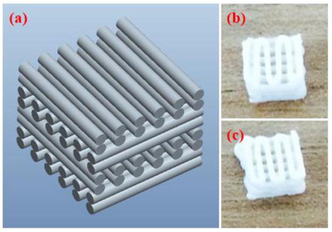
CAD drawing and 3D printed BCP scaffolds. (a) Pro-E model of the fabricated slurry foams, showing alternating lattice structures, producing fully interconnected square pores. (b) BCP slurry foam from top after printing and curing (c) BCP/ZrO2 slurry foam from bottom after printing and curing. Final dimension of the printed scaffolds was at 8.5 × 8.5 × 3.2 mm.
2.3.2 Fabrication of 3D slurry foam
The FDM system was utilized to fabricate the 3D ceramic slurry foam. The dimension of the 3D slurry foam was maintained at 8.2 × 8.2 × 3.2 mm3. The ceramic slurry was deposited with an average pneumatic pressure of 600 kPa and feed rate of 100 mm/min. The ceramic slurry was deposited through a taper nozzle of 610 μm. The 3D slurry foam with lattice-type shape was fabricated by a layer by layer fabrication process. The line width and pore size of the 3D slurry foam were 600 and 400 μm, respectively. The fabricated slurry foam was heated and dried using the oven for 1 h at 100°C. Finally, 3D slurry foam was successfully fabricated using a FDM system, as shown in Fig. 2(b and c). Fig. 2(b and c) shows the BCP and BCP/ZrO2 slurry foams from top after printing and curing.
2.4 Sintering process of the slurry foam
All fabricated slurry foams were dried at room environment for 1 day to sinter by a furnace. Sintering process is very essential requirements to achieve pure bioceramics scaffolds. The dried slurry foams were sintered according to the heating schedule. In first step, the sintering temperature was risen for 2 h from room temperature to 600°C. In second step, slurry foams were maintained for 1 h at 600°C to burn out the blending materials. Lastly, scaffolds were maintained for 2 h after rising for 1 h to 1,100°C.
2.5 SEM/EDS analysis
All prepared scaffolds were gold-coated with a sputter coater for 50 s. Then, a scanning electron microscope-energy dispersive spectroscopy (SEM-EDS, Tescan VEGA II, Czech) was used to confirm the morphology and chemical composition of scaffolds. Observation of scaffolds was carried out at acceleration of 20 kV. After setting up all adjusting functions, overall shape and pore of scaffolds were observed. Ions component on surface of scaffolds were also measured by EDS analysis.
2.6 Mechanical strength evaluation
The compression testing machine (JSV-H1000, JISC, Japan) was used for the mechanical testing of fabricated scaffolds. The scaffolds had the dimension of about 6.0 × 6.0 × 3.0 mm3. In the compression test, scaffolds were compressed at a cross-head speed of 1 mm/min in the direction perpendicular. Compressive strength was calculated from the stress-strain curves. The stress-strain data was computed from load-displacement measurements. Compressive modulus was determined based on the slope of the stress-strain curve in the elastic region.
2.7 Cell culture and seeding using MG63
Osteoblast-like osteosarcoma MG-63 cells we cultured in Dulbecco’s modified Eagle’s medium (DMEM, Hyclone, Logan, UT, USA) containing 10% fetal bovin serum (FBS, Gibco, Rockville, MD, USA) and 1% penicillin/streptomycin (PS, Sigma, St. Louis, MO, USA) in an atmosphere of 5% CO2 at 37°C for 4 days, and the culture medium was replaced every day. 5×10⁴ cells/scaffold was seeded onto each scaffold. Cell proliferation was assessed by cell counting kit-8 (CCK-8, Dojindo Molecular technologies, Japan) assay. The culture media and CCK-8 solution were mixed at a ratio of 10:1. The optical density (OD) level of extracted suspension was determined by measuring at 450 nm using a micro reader (UVM 340, Elisa, USA).
2.8 Cell seeding and differentiation using hMSCs
2.8.1 Cell seeding, differentiation, and cell viability
hMSCs (passage 3) (RoosterBio, Frederick, MD) were seeded onto various types of scaffolds (1 million cells/scaffold) and cultured for 5 days in hMSC growth media under static conditions. This allowed for confluency and proliferation of hMSCs on the scaffolds. Cell-seeded scaffolds were then osteogenically differentiated for 21 days using hMSC growth media supplemented with 100 nM dexamethasone, 10 mM β-glycerophosphate, and 173 mM ascorbic acid as previously described in either static or dynamic conditions using the TPS bioreactor (Yeatts et al., 2011a; Yeatts and Fisher, 2011b; Nguyen et al., 2016a; Nguyen et al., 2016b). Static scaffolds were cultured in 6-well plates (Corning) and 5 mL of osteogenic media, while scaffolds under dynamic conditions were cultured under 3 mL shear flow in the TPS bioreactor. Static control scaffolds in hMSC growth media were used as control. Media was exchanged every 2–3 days. On days 1, 14, and 21, scaffolds were removed and cells were isolated for further analysis, such as viability, gene, and protein expressions. To observe cell viability, BCP and BCP/ZrO2 scaffold samples were incubated with 4 μm Ethidium Homodimer (EH) and 2 μm Calcein AM (Life Technologies) in PBS for 30 minutes and then imaged with a fluorescent microscope (Zeiss, Germany). Images on Day 21 were further analyzed using Image J (NIH) to quantify the percent viability of the cells in each group (n=3).
2.8.2 qRT-PCR
To quantify gene expression of differentiated hMSCs, the cells were removed and isolated from the scaffolds using trypsin/EDTA (Invitrogen) and a cell pellet was formed by centrifugation. The RNeasy Plus Mini Kit (Qiagen, Frederick, MD) was used to isolate total RNA from hMSCs using following standard protocols. Total RNA was quantified using a Nanodrop Spectrometer (Thermo Scientific, Wilmington, DE). Isolated RNA was then reverse transcribed to cDNA using a High Capacity cDNA Archive Kit (Life Technologies, Frederick, MD). Quantitative RT-PCR was performed by combining the cDNA solution with a Universal Master Mix (Life Technologies), as well as oligonucleotide primers and Taqman probes for BMP-2, and compared to the endogenous gene control glyceraldehyde 3 phosphate dehydrogenase (GAPDH) (Life Technologies). The reaction was performed using a 7900HT real-time PCR System (Applied Biosystems) at thermal conditions of 2 min at 50°C, 10 min at 95°C, 40 cycles of 15 s at 95°C, and 1 min at 60°C. The relative gene expression level of each target gene was then normalized to the mean of day 0 GAPDH expression in each group and. Fold change was calculated using the ΔΔCT relative comparative method as described previously and represented in comparison to day 0 static control results. Samples were completed in technical triplicates and standard deviations are reported (n=3).
2.9 Statistics
All data was analyzed using one-way analysis of variance and Turkey’s multiple-comparison test to determine statistical differences between hydrogels. A confidence interval of 95% (α = 0.05) was used for all analyses, and means and SDs are shown in each figure.
3. Results and discussion
3.1 Fabrication and morphology of BCP/ZrO2 scaffold
In this study, BCP and BCP/ZrO2 scaffolds were sintered at 1,100°C to obtain the stable β-TCP phase preferred as scaffold requirements of chemical stability, mechanical strength, and proper bioresorption rate (Ryu et al., 2002). Fig. 3 shows weight loss and shrinkage results of BCP and BCP/ZrO2 scaffolds after sintering process. Fig. 3(a) shows weight loss result of the scaffolds. Weight of BCP and BCP/ZrO2 scaffolds was decreased after sintering, and showed a difference value of 4.4 %. Fig. 3(b) presents shrinkage result about dimension of the scaffolds. Dimension of the scaffolds was decreased after sintering, and showed a difference value of 4.5 %. These results are direct proof that the scaffolds have a similar difference value between weight loss and shrinkage through sintering process. The main reason may be that weight loss and shrinkage phenomenon will be caused by the removal of the blending materials and the aggregation of bio-ceramic powders, respectively.
Figure 3.

Weight loss and shrinkage results of BCP and BCP/ZrO2 scaffolds after sintering process. (a) Calculated weight loss using the weight ratio between BCP and BCP/ZrO2 scaffolds, depicting a 4.4% greter weight loss in BCP/ZrO2 scaffolds. (n=4) (b) Shrinkage of the scaffolds using volume ratios showed a 4.5% difference between BCP and BCP/ZrO2 scaffolds. (n=4)
The SEM images of the BCP/ZrO2 scaffold were shown in Fig. 4. The fabricated scaffold had an overall size of 6.0 × 6.0 × 3.0 mm3. The BCP/ZrO2 scaffold was approximately 350 μm in pore size and 500 μm in line width from the SEM image. The EDS mapping given in Fig. 5 reveal that the surface of the BCP scaffold consists of phosphate (P) and calcium (Ca) whereas other ions are not detected. The EDS mapping given in Fig. 6 reveals that the surface of the BCP/ZrO2 scaffold consists of mainly P, Ca, and zirconia (Zr) whereas other ions are not detected. The ZrO2 particles were uniformly distributed with BCP particles in BCP/ZrO2 scaffold. The results show that all of the organic components in the BCP/ZrO2 scaffolds are burned out during sintering process.
Figure 4.

SEM images of BCP/ZrO2 scaffold. Left image shows pore size of approximately 350 μm and printed lattice width of 500 μm. Right side depicts a granular surface of the 3D printed scaffold after printing and sintering.
Figure 5.

Ouantitative analysis results of BCP scaffold using EDS on SEM. (a) Image of surface area used to analyze the scaffolds for their composition. Table results show the percentage of oxygen, phosphate, calcium, and gold (from sputtering). (b) Graph shows that majority of the surface composition of the scaffold is made up of phosphate and calcium. (c) Mapping image of phosphate. (d) Mapping image of calcium.
Figure 6.

Quantitative analysis results of BCP/ZrO2 scaffold using EDS on SEM. (a) Image of surface area used to analyze the scaffolds for their composition. Table results show the percentage of oxygen, phosphate, calcium, zirconia, and gold (from sputtering). (b) Graph shows that majority of the surface composition of the scaffold is made up of phosphate, calcium, and zirconia.(c) Mapping image of phosphate. (d) Mapping image of calcium. (e) Mapping image of zirconia.
3.2 Mechanical property of porous BCP/ZrO2 scaffold
The compressive strength of the fabricated BCP/ZrO2 scaffolds was investigated by a compression testing machine. The graph on compressive strength of BCP and BCP/ZrO2 scaffolds was respectively shown in Fig. 7. It could be seen that the compressive strength of BCP scaffold with 0 wt% ZrO2 powders was 0.5 MPa and increased to 1.0 MPa with 10 wt% ZrO2 powders. The compressive strength of BCP scaffold increased almost linearly with cracking. In contrast, BCP/ZrO2 scaffold presented apparent transgranular fracture due to the agglomeration of 10 wt% ZrO2 powder. Through this study, it is demonstrated that the compressive strength can be greatly enhanced by addition of ZrO2 powders. The compressive strength of human cancellous bone ranges between 2~12 Mpa (Triphthi and Basu, 2012). However, the BCP/ZrO2 scaffold on this step has not any sufficient compressive strength for bone unfortunately.
Figure 7.
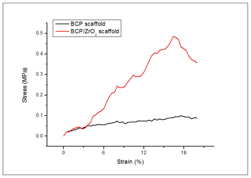
Stress-strain curves of BCP and BCP/ZrO2 scaffolds. The stress-strain curve was used to calculate the compressive strength of the scaffolds. Results indicate that the compressive strength for BCP/ZrO2 scaffolds (red) is greater compared to BCP scaffolds (black).
The 3D scaffold must have a sufficient strength to maintain the space for the formation of a substrate and the growth of cells within in-vitro. In an in-vivo, it is reported that the compressive strength of porous 3D scaffold for bone tissue regeneration may be one of the important factors because bone is under physiological stress such as bone compression, tension, torsion, bending. Therefore, the mechanical properties of the grafted scaffold should be approximately similar to the living bone as it can expect the fast recovery of the wound (O’Brien, 2011; Hollister, 2005). To increase the mechanical strength, BCP/ZrO2 scaffold can perform the additional study that raise sintering temperature or increase amount of ZrO2 powder. However, Ryu et al. reported that β-TCP is stable below 1,180°C. Also it has certain characteristics that are preferred as bioresorption rate (Ryu et al., 2003). Hence, in this study, the BCP and BCP/ZrO2 scaffolds were sintered at 1,100°C for 2 h.
According to the recent studies, some biomaterials such as ZrO2, SiO2, and PLLA had been applied to increase the mechanical properties of bioceramics scaffolds. An et al. fabricated ZrO2/HA scaffold with (ZrO2/HA: 0/100, 50/50, 60/40, 70/30, 80, and 100/0) using polyurethane sponge method. Compressive strength of ZrO2/HA scaffolds sintered at 1,500°C for 5 h increased from 0.3 ± 0.01 to 13.8 ± 0.94 MPa as addition of the ZrO2. These results suggested that ZrO2/HA scaffold was due to the phase change of β-TCP into α-TCP phase and densification of ZrO2 by very high sintering temperature over 1,500 °C(An et al., 2012). Feng et al. reported the effect of HA toughness on calcium silicate scaffolds using SLS technique. Compressive strength of calcium silicate scaffolds was improved from 18.19 ± 1.25 MPa to 27.28± 0.70 MPa as the HA whiskers increased from 0 to 30 wt% (Feng et al., 2014a).
3.3 Cell proliferation evaluation using MG63 cells
To ensure that the 3D printed scaffolds are in-vitro biocompatibility to relevant bone tissue engineering cell types, osteoblast-like MG63 cells were cultured on BCP and BCP/ZrO2 using CCK-8 assay. MG63 are a common cell type used to study cell proliferation on scaffolds, as they not only indicate non-cytotoxicity of the substrate but also mimic the final cell type in bone tissue engineering applications. Fig. 8 shows the proliferation result of MG63 cells after culturing for 7 days. At day 7 of culture, OD value of both BCP and BCP/ZrO2 scaffolds showed significantly higher cell proliferation. In this study, it is demonstrated that the addition of 10 wt% ZrO2 powder does not bring into any bad influence in cell proliferation. These results suggest that the addition of ZrO2 powder could significantly increase in-vitro biocompatibility of porous BCP/ZrO2 scaffold.
Figure 8.
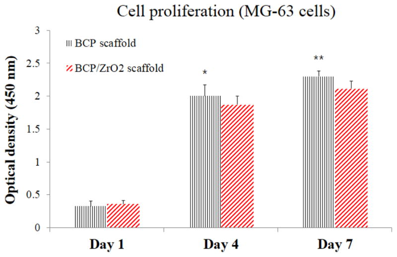
Cell proliferation results on the BCP and BCP/ZrO2 scaffolds using MG63 cells for 7 days. Statistical difference between OD levels was observed between the BCP and BCP/ZrO2 scaffolds over the 7 days, excluding day 1. However, cells seeded on BCP scaffolds (black) and BCP/ZrO2 scaffolds (red) showed similar cell proliferation after 7 days, indicating no adverse effects on cell viability due to the addition of ZrO2. (*p<0.05 and **p<0.01, compared with a BCP/ZrO2 scaffold, n=4)
3.4 Cell viability and differentiation
To investigate the use of BCP or ZrO2-reinforced BCP scaffolds in bone tissue engineering applications, we seeded human mesenchymal stem cells (hMSCs) onto the scaffolds and observed their osteogenic differentiation potential under static or dynamic culturing conditions. Observations from this cell culture study would reinforce the biocompatibility and non-cytotoxic characteristics of the 3D-printed scaffolds, and demonstrate the ability for hMSCs to differentiate into precursors of osteoblasts, similar to MG63 cells. Specifically, we utilized the tubular perfusion system (TPS) bioreactor to apply shear flow to the cells, which has demonstrated enhanced osteogenic differentiation in hMSCs. Throughout the study, cell viability was evaluated using fluorescence staining (Fig. 9a). Images taken at 2.5x magnification (top row) after 5 days of hMSCs proliferation showed a homogenous distribution of cells on the surface of the scaffolds. The cells remained highly viable (green) on both scaffold types in static and dynamic conditions and formed a confluent layer by day 21. Cells cultured in static growth media visibly proliferated and occupied the pores of the scaffold by day 14 and 21. These fluorescent viability images taken on Day 21 at 10x magnification were quantified using Image J to determine the percent live and dead for each group (Fig. 9b, n=3). The results confirmed the qualitative data, showing high viability, greater than 65% in each group and reaching 91% in the dynamic culturing conditions on BCP scaffolds. The percent of non-viable cells was highest in the static BCP group at 35%, followed by the static control BCP group and the static BCP/ZrO2 group at 21.8% and 21.1%, respectively. However, the fluorescent images showed formation of cell layers across the scaffold pores in static conditions, as seen in Fig 9a, panel labeled Day 21 static control BCP. Similar cell layer formation was not seen in the dynamic groups. This is hypothesized to be due to the force of the flow through the scaffold and pores, preventing cells from migrating and crossing through the approximately 400 μm pore. Overall, the continued viability of cells in both culture conditions, static and dynamic, demonstrates that cells remained alive throughout the scaffold and that pore dimensions were sufficient in providing vital nutrients to cells in the core of the scaffold. To quantify expression of osteogenic markers, we analyzed the cells for BMP-2 gene expression, an important marker and growth factor of osteogenesis (Fig. 10). On day 1 of static or dynamic culture, we did not see a difference between BMP-2 expressions on the different scaffolds or between culture conditions. On day 14, BMP-2 expression in the control group (solid green) had not significantly changed from day 1 values. However, all other groups (static BCP, static BCP/ZrO2, dynamic BCP, and dynamic BCP/ZrO2) showed statistically significant increases in BMP-2 expression over the static control group. There were also statistically significant differences in expression between static and dynamic BCP scaffolds, but no difference between static and dynamic BCP/ZrO2 scaffolds. Lastly, we observed continuous increased BMP-2 expression over 21 days of culture, especially in cells cultured in the TPS bioreactor (striped bars) compared to static conditions (solid bars). More importantly, cells seeded on BCP-ZrO2 scaffolds expressed significantly greater BMP-2 mRNA compared to BCP control group by day 21. Yet the addition of dynamic culture to BCP/ZrO2 cell-seeded scaffolds did not result in any significant increase in BMP-2 expression compared to the same scaffold in static culture. This indicates that while dynamic culture may make a noticeable impact on day 14 of osteogenic differentiation, by day 21, the important benefit of ZrO2 when added to BCP scaffolds is more critical for osteogenic differentiation than dynamic culture. In Fig 10, groups with the same letters indicate no statistical difference between groups for that time point, with p<0.05.
Figure 9.

Figure 9a. Fluorescent viability imaging of hMSCs on BCP and BCP/ZrO2 scaffolds. Cells were labeled with Ethidium Homodimer (green, live) and Calcein AM (red, dead). Top row shows imaged taken at 2.5x, and rows 2–4 show images at 10x.
Figure 9b. Quantification of hMSCs viability on BCP scaffolds on Day 21 under static and dynamic conditions. Fluorescence images of cells on scaffolds were counted (n=3), yielding percent viable (green) and percent non-viable cells (red) of total cells counted. Results indicate significantly greater viability of cells compared to non-viable cells in all groups on day 21 (p<0.05).
Figure 10.
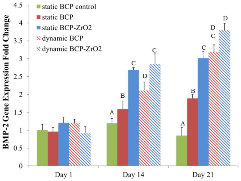
Osteogenic gene expressions of hMSCs on BCP and BCP/ZrO2 scaffolds. Groups with the same letters indicate no statistical difference between groups for that time point, with p<0.05. Results indicate significantly greater expression of BMP-2 in BCP/ZrO2 compared to BCP scaffolds on Day 21, but dynamic culture did not affect BMP-2 gene expression.
4. Conclusion
In this study, the blended BCP/ZrO2 scaffold was fabricated by FDM system. BCP scaffold with the addition of 10 wt% ZrO2 powder has led to higher compressive strength. Besides, we evaluated the cell proliferation of BCP/ZrO2 scaffold, and it was found that BCP/ZrO2 scaffold had a good biocompatible property on proliferation of MG63 cells for 7 days. hMSCs also showed great viability on the 3D printed BCP and BCP/ZrO2 scaffolds over 21 days in culture. Additional results of this study demonstrated the use of a novel biomaterial for osteogenic differentiation of hMSCs when cultured on 3D printed BCP-ZrO2 scaffolds in the TPS bioreactor. Specifically, increased expression of osteogenic genes and proteins suggests a synergistic effect of zirconia-fortified scaffolds and dynamic culture on osteogenic differentiation for the application of bone tissue engineering.
Acknowledgments
This research was supported by Basic Science Research Program through the National Research Foundation of Korea (NRF) funded by the Ministry of Education (NRF. 2016R1D1A3B03933081). Additionally, portions of this study were funded by the National Institute of Arthritis and Musculoskeletal and Skin Diseases of the National Institutes of Health (R01 AR061460), as well as by the National Science Foundation (CBET 1264517). This work was also supported by a National Science Foundation Graduate Fellowship to BNBN.
References
- Ahn GS, Lee JY, Seol DW, Pyo SG, Lee DH. The effect of calcium phosphate cement-silica composite materials on proliferation and differentiation of pre-osteoblast cells. Mater Lett. 2013;109:302–305. [Google Scholar]
- An SH, Matsumoto T, Miyajima H, Nakahira A, Kim KH, Imazato S. Porous zirconia/hydroxyapatite scaffolds for bone reconstruction. Dent Mater. 2012;28(12):1221–1231. doi: 10.1016/j.dental.2012.09.001. [DOI] [PubMed] [Google Scholar]
- Chuenjitkuntaworn B, Inrung W, Damrongsri D, Mekaapiruk K, Supaphol P, Pavasant P. Polycaprolactone/Hydroxyapatite composite scaffolds: Preparation, characterization, and in vitro and in vivo biological responses of human primary bone cells. J Biomed Mater Res A. 2010;94(1):241–251. doi: 10.1002/jbm.a.32657. [DOI] [PubMed] [Google Scholar]
- Feng P, Wei P, Li P, Gao C, Shuai C, Peng S. Calcium silicate ceramic scaffolds toughened with hydroxyapatite whiskers for bone tissue engineering. Mater Charact. 2014a;97:47–56. [Google Scholar]
- Feng P, Wei P, Shuai C, Peng S. Characterization of mechanical and biological properties of 3-D scaffolds reinforced with Zinc Oxide for bone tissue engineering. Plos One. 2014b;9(1):e87755. doi: 10.1371/journal.pone.0087755. [DOI] [PMC free article] [PubMed] [Google Scholar]
- Fielding GA, Bandyopadhyay A, Bose S. Effects of silica and zinc oxide doping on mechanical and biological properties of 3D printed tricalcium phosphate tissue engineering scaffolds. Dent Mater. 2012;28(2):113–122. doi: 10.1016/j.dental.2011.09.010. [DOI] [PMC free article] [PubMed] [Google Scholar]
- Gao C, Yang B, Hu H, Liu J, Shuai CC, Peng S. Enhanced sintering ability of biphasic calcium phosphate by polymers used for bone scaffold fabrication. Mater Sci Eng C. 2013;33(7):3802–3810. doi: 10.1016/j.msec.2013.05.017. [DOI] [PubMed] [Google Scholar]
- Guobao W, Peter XM. Structure and properties of nano-hydroxyapatite/polymer composite scaffolds for bone tissue engineering. Biomaterials. 2004;25(19):4749–4757. doi: 10.1016/j.biomaterials.2003.12.005. [DOI] [PubMed] [Google Scholar]
- Hollister SJ. Porous scaffold design for tissue engineering. Nature Mater. 2005;4:518–524. doi: 10.1038/nmat1421. [DOI] [PubMed] [Google Scholar]
- Jayakumar R, Ramachandran R, Sudheesh Kumar PT, Divyarani VV, Srinivasan S, Chennazhi KP, Tamura H, Nair SV. Fabrication of chitin-chitosan/nano ZrO2 composite scaffolds for tissue engineering applications. Int J Biol Macromolec. 2011;49(3):274–280. doi: 10.1016/j.ijbiomac.2011.04.020. [DOI] [PubMed] [Google Scholar]
- Kim MS, Kim YH, Park IH, Min YK, Seo HS, Lee BT. PCL infiltration into a BCP scaffold strut to improve the mechanical strength while retaining other properties. Kor J Mater Res. 2010;20(6):331–337. [Google Scholar]
- Kim DH, Kim KL, Chun HH, Kim TW, Park HC, Yoon SY. In vitro biodegradable and mechanical performance of biphasic calcium phosphate porous scaffolds with unidirectional macro-pore structure. Ceram Inter. 2014;40(6):8293–8300. [Google Scholar]
- Liu FH, Shen YK, Lee JL. Selective laser sintering of a hydroxyapatite-silica scaffold on cultured MG63 osteoblasts in vitro. Int J Precis Eng Manuf. 2012;13(3):439–444. [Google Scholar]
- Macchetta A, Turner IG, Bowen CR. Fabrication of HA/TCP scaffolds with a graded and porous structure using a camphene-based freeze-casting method. Acta Biomater. 2009;5(4):1319–1327. doi: 10.1016/j.actbio.2008.11.009. [DOI] [PubMed] [Google Scholar]
- Martínez-Vázquez FJ, Perera FH, Miranda P, Pajares A, Guiberteau F. Improving the compressive strength of bioceramic robocast scaffolds by polymer infiltration. Acta Biomater. 2010;6(11):4361–4368. doi: 10.1016/j.actbio.2010.05.024. [DOI] [PubMed] [Google Scholar]
- Miranda P, Pajares A, Saiz E, Tomsia AP, Guiberteau F. Mechanical properties of calcium phosphate scaffolds fabricated by robocasting. J Biomed mater Res. 2008;85(1):218–227. doi: 10.1002/jbm.a.31587. [DOI] [PubMed] [Google Scholar]
- Nguyen BNB, Ko H, Fisher JP. Tunable osteogenic differentiation of hMPCs in tubular perfusion system bioreactor. Biotechnol Bioeng. 2016a;113(8):1805–1813. doi: 10.1002/bit.25929. [DOI] [PubMed] [Google Scholar]
- Nguyen BNB, Ko H, Moriarty RA, Etheridge JM, Fisher JP. Dynamic bioreactor culture of high volume engineered bone tissue. Tissue Eng Part A. 2016b;22(3–4):263–271. doi: 10.1089/ten.tea.2015.0395. [DOI] [PMC free article] [PubMed] [Google Scholar]
- O’Brien FJ. Biomaterials & scaffolds for tissue engineering. Mater today. 2011;14(3):88–95. [Google Scholar]
- Padmanabhan SK, Gervaso F, Carrozzo M, Scalera F, Sannino A, Licciulli A. Wollastonite/hydroxyapatite scaffolds with improved mechanical, bioactive and biodegradable properties for bone tissue engineering. Ceram Inter. 2013;39(1):619–627. [Google Scholar]
- Park KB, Park JW, Ahn HU, Yang DJ, Choi SK, Jang IS, Yeo SI, Seo JY. Comparative study on the physicochemical properties and cytocompatibility of microporous biphasic calcium phosphate ceramics as a bone graft substitute. J Korean Acad Periodontol. 2006;36(4):797–808. [Google Scholar]
- Ryu HS, Youn HJ, Hong KS, Chang BS, Lee CK, Chung SS. An improvement in sintering property of β-tricalcium phosphate by addition of calcium phosphate. Biomaterials. 2002;23(3):909–914. doi: 10.1016/s0142-9612(01)00201-0. [DOI] [PubMed] [Google Scholar]
- Sa MW, Kim JY. Design of multi-scaffold fabrication system for various 3D scaffolds. J Mech Sci Technol. 2013;27(10):2961–2966. [Google Scholar]
- Sa MW, Kim SE, Yun YP, Song HR, Kim JY. Fabrication of hybrid scaffolds by polymer deposition system and its in-vivo evaluation with a rat tibial defect model. Tissue Eng Regen Med. 2014;11(6):439–445. [Google Scholar]
- Sachlos E, Czernuszka JT. Making tissue engineering scaffolds work. Review: on the application of solid freeform fabrication technology to the production of tissue engineering scaffolds. Eur Cell Mater. 2003;5:29–39. doi: 10.22203/ecm.v005a03. [DOI] [PubMed] [Google Scholar]
- Salerno A, Oliviervo M, Maio ED, Lannace S, Netti PA. Design of porous polymeric scaffolds by gas foaming of heterogeneous blends. J Mater Sci Mater Med. 2009;20(10):2043–2051. doi: 10.1007/s10856-009-3767-4. [DOI] [PubMed] [Google Scholar]
- Seol YJ, Park DY, Park JY, Kim SW, park SJ, Cho DW. A new method of fabricating robust freeform 3D ceramic scaffolds for bone tissue engineering. Biotechnol Bioeng. 2013;110:1444–1455. doi: 10.1002/bit.24794. [DOI] [PubMed] [Google Scholar]
- Shuai C, Yang B, Peng S, Li Z. Development of composite porous scaffolds based on poly(lactide-co-glycolide)/nano-hydroxyapatite via selective laser sintering. Int J Adv Manuf Technol. 2013;69(1–4):51–57. [Google Scholar]
- Song YG, Cho IH. Characteristics and osteogenic effect of zirconia porous scaffold coated with β-TCP/HA. J Adv Prosthodont. 2014;6(4):285–294. doi: 10.4047/jap.2014.6.4.285. [DOI] [PMC free article] [PubMed] [Google Scholar]
- Tiainen H, Eder G, Nilsen O, Haugen HJ. Effect of ZrO2 addition on the mechanical properties of porous TiO2 bone scaffolds. Mater Sci Eng C Mater Biol Appl. 2012;32(6):1386–1393. doi: 10.1016/j.msec.2012.04.014. [DOI] [PubMed] [Google Scholar]
- Triphthi G, Basu BB. A porous hydroxyapatite scaffold for bone tissue engineering physic-mechanical and biological evaluations. Ceram Inter. 2012;38(1):341–349. [Google Scholar]
- Yeatts AB, Gordon CN, Fisher JP. Formation of an aggregated alginate construct in a tubular perfusion system. Tissue Eng Part C: Methods. 2011a;17(10):1171–1178. doi: 10.1089/ten.tec.2011.0263. [DOI] [PubMed] [Google Scholar]
- Yeatts AB, Fisher JP. Bone tissue engineering bioreactors: dynamic culture and the influence of shear stress. Bone. 2011b;48(2):171–181. doi: 10.1016/j.bone.2010.09.138. [DOI] [PubMed] [Google Scholar]