Abstract
Objective
Transcatheter aortic valve replacement is established therapy for high-risk and inoperable patients with severe aortic stenosis, but questions remain regarding long-term durability. Valve design impacts durability. Increased leaflet stresses in surgical bioprostheses have been correlated with degeneration; however, transcatheter valve leaflet stresses are unknown. From 2007–2014, a majority of US patients received first-generation balloon-expandable transcatheter valves. Our goal was to determine stent and leaflet stresses in this valve design using finite element analyses.
Methods
26mm Edwards Sapien (Edwards Lifesciences, Inc, Irvine, CA) underwent high-resolution micro-computed tomography scanning to develop precise 3D geometry of leaflets, stent, and dacron. Stent was modeled using 3D elements and leaflets using shell elements. Stent material properties were based on stainless steel, while those for leaflets were obtained from surgical bioprostheses. Non-cylindrical Sapien geometry was also simulated. Pressure loading to 80 and 120mmHg was performed using ABAQUS, finite element software (Dassault Systemes, Waltham, MA).
Results
At 80mmHg, maximum principal stresses on Sapien leaflets were 1.31MPa. Peak leaflet stress was observed at commissural tips where leaflets connected to the stent. Maximum principal stresses for stent was 188.91MPa, and located at stent tips where leaflet commissures were attached. Non-cylindrical geometry increased peak principal leaflet stresses by 16%.
Conclusions
Using exact geometry from high-resolution scans, 26mm Sapien showed that peak stresses for both stent and leaflets were present at commissural tips where leaflets were attached. These regions would be prone to initiate leaflet degeneration. Understanding stresses in first-generation transcatheter valves allow comparison to future designs for relative durability.
Graphical abstract
Introduction
Transcatheter aortic valve replacement (TAVR) was first performed in a human of prohibitive surgical risk in 2002 using balloon-expandable stainless steel stent with equine pericardial leaflets, Cribier-Edwards (Edwards Lifesciences, Inc, Irvine, CA) transcatheter aortic valve (TAV)1. Subsequently, equine leaflets were changed to bovine pericardium and the first generation Edwards Sapien valve (Edwards Lifesciences, Inc, Irvine, CA) was created. This first generation TAV was used in the pivotal PARTNER (Placement of Aortic Transcatheter Valves) randomized trials in the United States comparing TAVR to medical therapy in inoperable patients and TAVR to surgical aortic valve replacement (SAVR) in high-risk patients, beginning in April, 20072,3. TAVR proved to be superior to medical therapy4,5 for severe aortic stenosis (AS) in inoperable patients and equivalent to surgery in high-risk patients6. The second generation TAV, Edwards Sapien XT (Edwards Lifesciences, Inc, Irvine, CA), iterated the design to reduce stent profile using cobalt-chromium, and changed its leaflet design from open to semi-closed position. Sapien XT became FDA approved for commercial use in June, 2014; thus, presently in the US, thousands of patients have had the original Sapien TAV implanted.
However, as TAVR demonstrated equipoise with surgery in intermediate-risk patients7 and will proceed to lower risk surgical patients, one major concern is TAV long-term durability. Durability in surgical bioprostheses has been extensively studied8–10. Pathologically, bioprosthetic degeneration involves leaflet cusp calcification and stiffening, and leaflet tearing. Areas of increased stresses correlated with regions of calcific degeneration or leaflet tearing11,12. Understanding TAV leaflet stresses is the first step towards understanding TAV durability and the regions prone to degeneration. Presently, TAV leaflet stresses are unknown and cannot be directly measured, but can be determined through finite element analyses (FEA). FEA is an essential method to obtain valuable data about complicated real-world systems that would otherwise be impossible to directly measure. FEA when applied to medical device designs can be used to calculate stresses and investigate potential failure modes and locations. Finite element (FE) models require accurate three-dimensional geometry in the zero-stress state, material properties, and physiologic loading conditions. Our goal was to determine stent and leaflet stresses in the first generation 26mm Edwards Sapien TAV, which was implanted during the PARTNER trial and initial TAVR commercialization in the US. In addition, non-cylindrical TAV shape after implantation in the calcified aortic root has been observed which can cause moderate postoperative paravalvular regurgitation13. The distorted implanted TAV may experience higher stress level14.
Materials and Methods
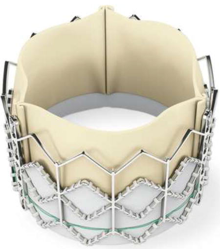
We obtained a commercial 26mm Edwards Sapien (external diameter 26mm, height 16.1mm), which consisted of 3 components: stainless steel stent, dacron covering, and bovine pericardial leaflets. Physical measurements were taken and the suture connections between different components were studied to enable accurate modeling of valve. Overview of the process to determine TAV stress distribution included: 1) micro-computed tomography (micro-CT) scanning of 26mm Sapien at 0mmHg, 2) development of TAV mesh using 3D geometry of leaflets, stent and dacron, 3) application of material properties of stent and leaflets followed by systemic pressure loading, and 4) FEA using finite element (FE) solver.
Sapien Transcatheter Aortic Valve Mesh Generation
Fully expanded Sapien (26mm) was imaged under 0mmHg pressure with desk-top cone-beam micro-CT scanner (microCT-40; Scanco Medical AG, Baseldorf, Switzerland) in different orientations and intensities to distinguish stent and leaflet geometries. Scan settings used were: X-ray energy--45kVp, X-ray current--200µA, filter--0.5mm aluminum, field of view--50mm, voxel size--50µm and integration time--200ms. High-resolution DICOM (Digital Imaging and Communications in Medicine) radiologic images (voxel size 50×50×50µm) were imported into MeVisLab, an open source surface reconstruction software (http://www.mevislab.de/). DICOM files were scanned individually to separate TAV stent vs. leaflets materials to obtain the most accurate representation of their respective geometries. Stent and leaflet surfaces were combined using suture lines as a reference point for leaflet orientation. Reconstructed surface was then imported into GeoMagic Design, (3DSystems, Rock Hill, SC, USA), a CAD (computer aided design) software, to refine and create the 3D geometric volume with accurate size and thickness at zero stress. The refined geometries of leaflets, stent and Dacron were then imported into HyperMesh (Altair Engineering, Troy, MI) to generate TAV mesh with 46,443, total number of elements.
Constitutive Model and Material Properties
TAV stent and leaflets were assigned material properties. Sapien used leaflets made of specially treated bovine pericardium to resist calcification and that proprietary process was the same as for corresponding surgical Carpentier-Edwards Magna pericardial valves (Edwards Lifesciences, Inc, Irvine, CA). Biaxial stretch testing of these surgical valves was performed to determine material properties of TAV leaflets, to avoid destroying leaflets of 26mm Sapien. Methods of biaxial stretching have been previously described (13). TAV leaflets were assumed to be anisotropic, non-linear hyperelastic and orthotropic materials. Material’s response to stress was described mathematically by a set of constitutive equations, derived from strain energy function W. Using Fung-type hyperelastic material, W was described as
where c, ci, and D are material parameters; Ejk and Elm are quadratic form of Green-Lagrangian strain; and J is the determinant of deformation tensor. Material parameters in the above equations are obtained from biaxial tensile tests previously conducted in our laboratory, as listed in Table 1. Stainless steel material properties were used for stent and it was modeled using an elastic-plastic material with Young’s modulus, Poisson’s ratio, yield stress and hardening parameters as material constants in Table 1.
Table 1.
Material constants for leaflets and stent.
| Leaflet | |||||
| c1 | c2 | c3 | c4 | c5 | c6 |
| 62.28 | 26.97 | 132.12 | 0.01 | 0.01 | 0.01 |
| c7 | c8 | c9 | c | D | |
| 31.14 | 0.01 | 0.01 | 5.01 | 0.000001 | |
| Stent | |||||
| Young’s Modulus | Poisson’s ratio | Yield stress | Ultimate stress | Strain at break | |
| 200 GPa | 0.3 | 330 MPa | 676 MPa | 0.5 | |
Finite Element Simulation
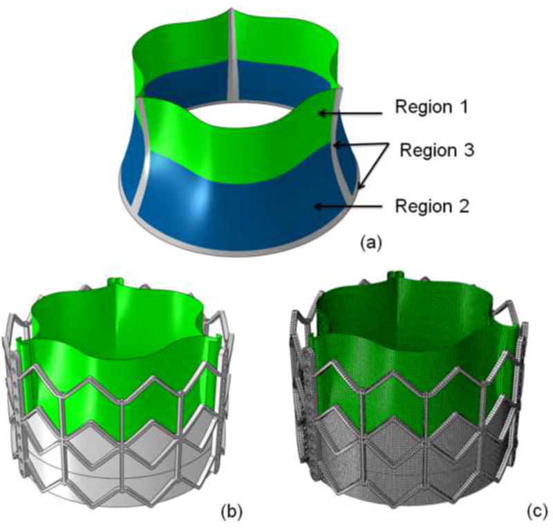
FE simulations were performed using commercial FE solver, ABAQUS (Dassault Systems, Waltham, MA). Stent geometry was modeled using 3-dimensional brick elements whereas leaflet geometry was modeled using nonlinear shell elements. Mesh sizes chosen for the stent and leaflets were 0.5mm and 0.25mm, respectively. Contact definitions between the leaflets and between leaflet and stent were investigated to choose one most accurately representing the overall behavior. Leaflet nodes were connected to the stent using a TIE contact (coefficient of friction value 0.1). TAV leaflet geometries were sutured to the Dacron mesh at the bottom as seen in figure 1 and tied to stent geometry at the top. TAV leaflet mesh was sub-divided into 3 distinct regions (figure 1a) to study stress distribution due to pressure loading: 1) sutured edges, 2) upper free edge region, and 3) lower belly region.
Figure 1.
a) Regions of interest studied for stress distribution in leaflets: region 1: upper leaflet free edges; region 2: lower leaflet belly; and region 3: sutured leaflet edges. b) Geometry of 26mm Sapien TAV. c) TAV finite element mesh.
To simulate elliptical shape of TAV after deployment based upon clinical post-TAVR patient CT data on Sapien15, additional displacement was applied to specified portions of the stent. The outline of stent and sutured leaflets were deployed to non-cylindrical shape with non-uniform radial distances. After deployment, simulations were performed to determine TAV stresses based upon arterial pressure on manufactured TAV without crimping and balloon-expansion. Non-distorted and distorted TAV stent and leaflets were exposed to systemic pressure of 80 and 120mmHg using quasi-static pressure loading. Boundary conditions were applied to TAV stent to prevent any rigid body motion. The longitudinal displacement of 9 proximal nodes of the stent was constrained to represent TAV deployment into diseased native valves.
Results
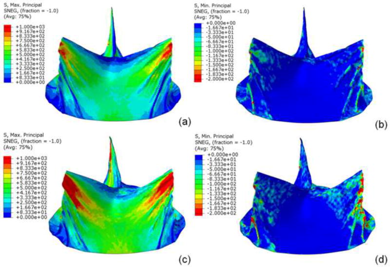
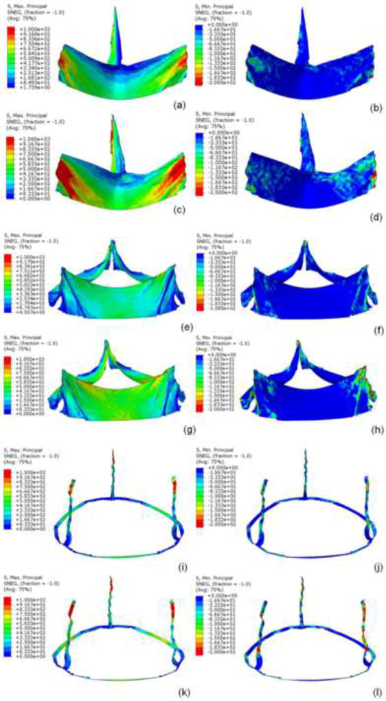
Sapien 26mm geometry including TAV leaflets, stent, and Dacron were precisely reconstructed and aligned. Leaflets were attached to Dacron and stent along suture lines. Data presented here was from a single optimized simulation after mesh refinement studies, adjusting the material parameters and boundary conditions. Sapien 26mm geometry and corresponding FE mesh are shown (figure 1). Loading and boundary conditions were applied to stent and leaflet assembly. Maximum and minimum principal stresses for entire leaflet assembly and each subregion, are shown for 80 and 120mmHg, using quasi-static loading condition (figure 2). High stress concentration locations were determined. Maximum principal stresses across entire leaflet, including sutured regions, at 80 and 120mmHg, were 2.54MPa and 3.06MPa, respectively (figure 3i,k). Minimum principal stresses across entire leaflet, including sutured regions, at 80 and 120mmHg, were −0.78MPa and −1.08MPa, respectively (figure 3j, l). Positive stress values correspond to tensile stress where TAV leaflets stretched to close, while negative stress values represent leaflet compression or bending where redundant tissue was compressed to close. Stress contours for each region are shown (figures 3a–l).
Figure 2.
a) Maximum and b) minimum principal stresses on entire leaflet assembly at 80mmHg and c) maximum and d) minimum principal stresses on entire leaflet at 120mmHg under quasi-static conditions.
Figure 3.
Under quasi-static conditions for region 1, a) maximum and b) minimum principal stress at 80mmHg and c) maximum and d) minimum principal stress at 120mmHg. For region 2, e) maximum and f) minimum principal stresses at 80mmHg, and g) maximum and h) minimum principal stresses at 120mm Hg. For region 3, i) maximum and j) minimum principal stresses at 80mmHg and k) maximum and l) minimum principal stresses at 120mmHg.
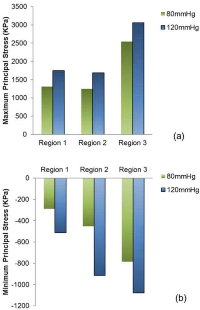
Region 3 (sutured edges) contained maximum and minimum principal stresses for the entire leaflet assembly (figure 3i–l). Peak stress occurred at tips of leaflet commissures along the attachment with the stent) (figure 2). In contrast, regions of free leaflet margin at the top and leaflet belly at the bottom, had much lower peak stresses. Upper free leaflet edges (region 1) had maximum (1.31MPa and 1.75MPa at 80 and 120mmHg, respectively) and minimum (−0.29MPa and −0.51MPa at 80 and 120mmHg, respectively) principal stresses in the region where commissure attached to the stent (figure 3a–d). Lower leaflet belly (region 2) had maximum (1.25MPa and 1.69MPa at 80 and 120mmHg, respectively) and minimum (−0.45MPa and −0.91MPa at 80 and 120mmHg, respectively) principal stresses, and stress was evenly distributed in the area of leaflet belly (figure 3e–h). Comparison of principal stresses for each leaflet region is plotted (figure 5). TAV simulations with and without stent are presented as online supplement (videos 1–2).
Figure 5.
Comparison of a) maximum and b) minimum principal stress contours for the 3 leaflet regions of interest at 80 and 120mmHg at quasi-static loading conditions.
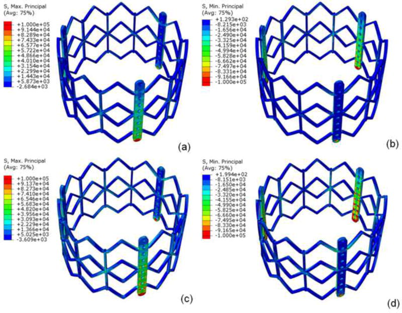
For TAV stent, maximum principal stresses at 80 and 120mmHg were 188.91MPa and 251.98MPa, respectively; minimum principal stresses at 80 and 120mHg were −258.49MPa and −362.99MPa, respectively (figure 4). Peak stresses occurred where longitudinal motion was constrained, at the proximal deployment in the annulus and where the leaflets were attached to stent/commissural posts. Maximum stress was present on the outside surface, while minimum stress was present on the inner surface.
Figure 4.
Under quasi-static loading, a) maximum and b) minimum principal stresses of stent at 80mmHg and c) maximum and d) minimum principal stresses at 120mm Hg.
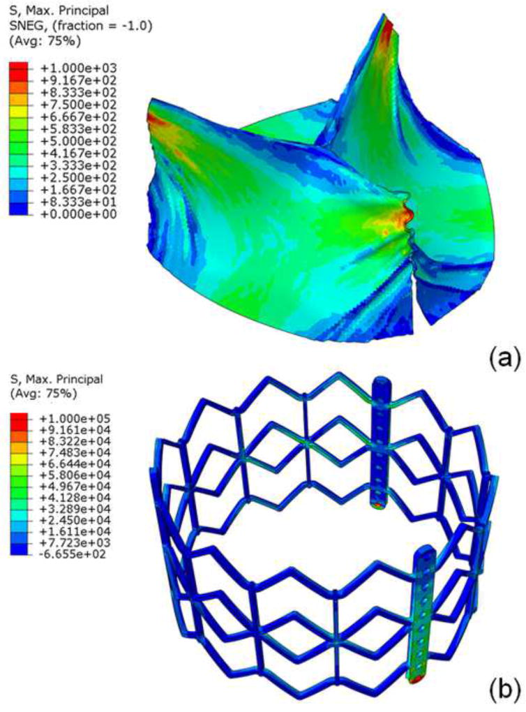
The distorted non-cylindrical TAV had an eccentricity, defined as 1-minimum diameter/maximum diameter, of 0.127, which was the largest eccentricity reported in a post-TAVR clinical CT study of Sapien15. For the distorted leaflets, upper free leaflet edges had maximum principal stresses of 1.52MPa (figure 6a) and minimum principal stresses of −0.36MPa at 80mmHg. The peak stress was located at the commissures where leaflets were attached to the stent, similar to that of cylindrical geometry. Lower leaflet belly had maximum principal stress of 0.83MPa and minimum principal stress of −0.36MPa at 80mmHg. The stent had maximum principal stress of 178.29Mpa (figure 6b) and minimum principal stress of −244.39MP at 80mmHg.
Figure 6.
For the non-cylindrical geometry, maximum principal stress of a) leaflet top and bottom and b) stent at 80mmHg.
Discussion
From the initiation of the PARTNER trial in 2007 to commercialization of the Edwards Sapien XT in 2014, the majority of patients in the US received the first generation Edwards Sapien TAV. However, the long-term durability of this valve design or its subsequent iterations is unknown. The 5 year outcomes of PARTNER trial revealed no structural valve dysfunction with maintenance of low gradients and increased valve area16. Short-term durability thus appears adequate, but much longer-term follow-up is required. Sapien was designed using bovine pericardium treated by the same anticalcification processes as the surgical Carpentier-Edwards aortic pericardial valves17. Due to the size constraints of TAVR 22 and 24Fr delivery systems, TAV leaflets needed to be thinner than surgical bioprostheses. Indeed reduction further to 18 then 14Fr delivery systems for Sapien XT and 3rd generation Sapien 3, respectively, required altering stent material to cobalt-chromium and thinner leaflets to achieve lower crimped TAV profile. Thinner leaflets translate into higher leaflet stresses unless compensated for by improvements in valve design. Yet, leaflet stresses cannot be measured, but require FE modeling to determine. Accurate FE models require precise 3D geometry in zero-stress state, material properties, and physiologic loading conditions. Previous FEA studies have attempted to determine TAV leaflet stresses using a generic estimated leaflet geometry based on surgical valves and homemade TAVs18,19. However, exact TAV, particularly leaflet, geometry was not utilized. On the other hand, patient-specific FEA simulations have used exact TAV stent geometry to investigate the interaction of TAV stent with surrounding aortic root geometry, but did not focus on precise TAV leaflet geometry and thereby stresses20–22. Our study focused on FEA of TAV stresses using high-resolution micro-CT imaging of Sapien to obtain accurate 3D geometry at nominal dimensions as a benchmark for comparison with future generations of TAVs or surgical valves.
In this study, we demonstrated that maximum and minimum principal stresses in 26mm Sapien occurred proximally in the annulus, where the stent was deployed and confined. Overall, maximum and minimum principal stresses occurred where TAV leaflets were attached to the stent at the commissures. For the flexible regions of TAV leaflet, peak stresses were in the upper ‘V” shaped area approaching the commissure at systolic pressure. These regions of peak stress or locally higher stresses would be areas most prone to initiating degeneration. Relative durability of TAVR compared to surgical bioprosthesis clinically is unknown. In studies of surgical bioprostheses, degeneration by calcification or leaflet tearing correlated with areas of high tensile and compressive stresses23 as well as cyclic flexural fatigue and bending12. Sacks’ group performed FEA of 2 Edwards bovine pericardial valves under 120mmHg quasi-static loading conditions, with leaflet material properties determined from those valves and exact valve geometry11. Depending on which leaflet material properties were used, maximum in-plane stress ranged from 544.7 to 663.2kPa. Leaflet stresses were greatest near the commissures and least near the free edge. Based upon subsequent studies, their study used the 25mm surgical bioprosthesis, which is the most similar in size to our 26mm Sapien. Leaflet attachment to the stent can impact leaflet stress and their study attached the leaflets to the wire frame of the surgical bioprosthesis. In our study, maximum principal stress for 26mm Sapien was significantly higher than that reported for surgical bioprosthesis, which may reflect differences in leaflet design or leaflet interaction with their respective frames. Chandran’s group performed a dynamic FEA simulation with physiologic arterial pressures of 23mm bovine pericardial Edwards bioprosthesis24. They demonstrated peak von Mises stress of 2.09MPa located at the cuspal commissures in the fully closed position. Peak stresses increased significantly with dynamic leaflet motion. Our simulation yielded higher peak von Mises stresses of 3.72MPa in the quasi-static condition. Direct comparisons with Chandran’s study are not possible because larger valve sizes may have higher stresses and Chandran studied 23mm bioprosthesis. However, these studies suggest that dynamic simulations of 26mm Sapien may yield higher leaflet stresses.
Comparison with TAV Simulations
Sun’s group performed quasi-static simulations to 120mmHg of TAVs, using estimated leaflet geometry (22mm leaflet diameter), and varying thickness of porcine and bovine pericardium18. Maximum principal stress was 915.62kPa for bovine and 1565.80kPa for porcine pericardial leaflets at the fully loaded position. Thinner leaflets resulted in higher stresses and peak stresses occurred along leaflet-stent attachment along the commissures. Another study by Azadani reported maximum principal stress of 2.52MPa of a 23mm homemade TAV25. None of the above studies included a fully assembled TAV including leaflets, stent, Dacron, and sutures as in our study. Our study shows greater leaflet stresses than previous reported peak stresses, and those differences may reflect 1) our larger TAV diameter, 2) incorporation of stent and dacron to reflect interactive constraints on leaflets, and 3) exact leaflet geometry and thickness.
Several studies have examined Sapien TAVR in patient-specific simulations20,21, using CT images for geometry. They investigated biomechanical interactions of TAV stent with surrounding calcified aortic valve and root to determine risk of coronary obstruction, paravalvular leak, and aortic root rupture. They typically ignored TAV leaflets in simulation and none reported leaflet stresses. Morganti et al. performed 26mm SapienXT TAVR simulations in 2 patient cases and examined stresses in the aortic root to estimate risk of rupture21. They did demonstrate evidence of leaflet asymmetry based on patient-specific anatomy but did not report the impact of asymmetry on TAV leaflet stresses. Sun’s group did investigate the impact of TAVR deployment asymmetry on leaflet stresses in generic 23mm TAV14. They found peak leaflet stresses increased by 58.6% and 143.2% depending on the orientation of ellipticity. Maximum principal stresses increased from baseline of ~900kPa for complete leaflet symmetry to 1.1–2.2MPa depending on degree of eccentricity and orientation of ellipticity. Our baseline TAV stresses with leaflet symmetry was higher than their results due to our valve size, use of precise leaflet geometry and thickness. For non-cylindrical distorted geometry, peak first principal stress increased 16% in our model deployed asymmetrically, which fell within the incremental range of the previous study14. Notably, clinical studies of Sapien did not reveal the extremes of ellipticity demonstrated in Sun’s study.
Study Limitations
Our study did not take into account crimping and ballooning process which occurs during TAVR. Studies have demonstrated that the crimping process physically damages TAV leaflets and that may weaken leaflets and increase leaflet stress26. We did not destroy our TAV to test its leaflets for exact material properties given the rarity of obtaining TAVs and need for future TAV experimental in vitro tests, which are beyond the scope of this study. As such we utilized excised leaflets from surgical bioprostheses to determine material properties for TAV leaflets. While treatment processes for both Edwards valves is expected to the same, thinner pericardial leaflets used in TAVR may have different material properties18 than were represented here. As stent and leaflet stresses cannot be directly measured, our analyses of stress cannot be experimentally validated. Determinations of strain experimentally are beyond the scope of this work and will be considered for future studies. Complex fluid-structure interaction simulations were not incorporated and beyond the present scope of this study. Geometry used in this work was based on a single 26mm Sapien. Manufacturing process can introduce geometrical variations. Their impact on the stress results is not investigated in this study. We used averaged material properties and pressure loading conditions for stress analysis and the results should be considered as the “averaged” or representative stress results. Lastly, the current study does not include simulation of a SAVR of same size but rather compared our results with a previous study, which may not correlate exactly for quantitative comparisons11.
Conclusions
We determined TAV stent and leaflet stresses on Sapien 26mm using exact geometry. We demonstrated that maximum stresses occurred at the stent proximally in the annulus where leaflets were attached, and at leaflet commissures where they attached to the stent. These leaflet regions will likely be areas where degeneration initiates. Future comparisons with surgical bioprostheses of comparable size will be necessary to compare relative durability based on valve design.
Supplementary Material
Video 1. Maximum principal stress on 26mm Sapien TAV leaflets and stent under quasi-static diastolic pressure.
Central Message.
First generation Sapien has peak stresses at commissures, which may initiate eventual bioprosthetic calcification and degeneration.
Perspective Statement.
With transcatheter valves moving to intermediate-risk patients, questions arise regarding long-term durability. Stress analyses are important for evaluating durability relative to surgical bioprotheses or newer devices. We demonstrated that peak leaflet stresses in first generation Sapien occurred at leaflet commissures at stent attachment sites, suggesting regions prone to initiating degeneration.
Acknowledgments
Funded by the University of California Office of the President, University of California Proof of Concept grant #246590.
Abbreviations and Acronyms
- TAVR
transcatheter aortic valve replacement
- TAV
transcatheter aortic valve
- PARTNER
placement of aortic transcatheter valves
- SAVR
surgical aortic valve replacement
- AS
aortic stenosis
- FEA
finite element analyses
- FE
finite element
- mm
millimeter
- KPa
kilopascal
- MPa
megapascal
- GPa
gigapascal
Footnotes
Presented at Transcatheter Cardiovascular Therapeutics 2014, Washington DC, September 14, 2014.
The authors have no conflicts of interest.
References
- 1.Cribier A, Eltchaninoff H, Bash A, et al. Percutaneous transcatheter implantation of an aortic valve prosthesis for calcific aortic stenosis first human case description. Circulation. 2002;106(24):3006–3008. doi: 10.1161/01.cir.0000047200.36165.b8. [DOI] [PubMed] [Google Scholar]
- 2.Leon MB, Smith CR, Mack M, et al. Transcatheter aortic-valve implantation for aortic stenosis in patients who cannot undergo surgery. New England Journal of Medicine. 2010;363(17):1597–1607. doi: 10.1056/NEJMoa1008232. [DOI] [PubMed] [Google Scholar]
- 3.Smith CR, Leon MB, Mack MJ, et al. Transcatheter versus surgical aortic-valve replacement in high-risk patients. New England Journal of Medicine. 2011;364(23):2187–2198. doi: 10.1056/NEJMoa1103510. [DOI] [PubMed] [Google Scholar]
- 4.Ye J, Cheung A, Lichtenstein SV, et al. Transapical transcatheter aortic valve implantation: 1-year outcome in 26 patients. The Journal of Thoracic and Cardiovascular Surgery. 2009;137(1):167–173. doi: 10.1016/j.jtcvs.2008.08.028. [DOI] [PubMed] [Google Scholar]
- 5.Ye J, Cheung A, Lichtenstein SV, et al. Transapical transcatheter aortic valve implantation: Follow-up to 3 years. The Journal of Thoracic and Cardiovascular Surgery. 2010;139(5):1107–1113.e1. doi: 10.1016/j.jtcvs.2009.10.056. [DOI] [PubMed] [Google Scholar]
- 6.Crouch G, Bennetts J, Sinhal A, et al. Early effects of transcatheter aortic valve implantation and aortic valve replacement on myocardial function and aortic valve hemodynamics: Insights from cardiovascular magnetic resonance imaging. The Journal of thoracic and cardiovascular surgery. 2015;149(2):462–470. doi: 10.1016/j.jtcvs.2014.10.064. [DOI] [PubMed] [Google Scholar]
- 7.Leon MB, Smith CR, Mack MJ, et al. Transcatheter or surgical aortic-valve replacement in intermediate-risk patients. New England Journal of Medicine. 2016;374(17):1609–1620. doi: 10.1056/NEJMoa1514616. [DOI] [PubMed] [Google Scholar]
- 8.Bourguignon T, Bouquiaux-Stablo A-L, Candolfi P, et al. Very long-term outcomes of the Carpentier-Edwards Perimount valve in aortic position. The Annals of thoracic surgery. 2015;99(3):831–837. doi: 10.1016/j.athoracsur.2014.09.030. [DOI] [PubMed] [Google Scholar]
- 9.Stamou SC, Williams ML, Gunn TM, Hagberg RC, Lobdell KW, Kouchoukos NT. Aortic root surgery in the United States: a report from the Society of Thoracic Surgeons database. The Journal of thoracic and cardiovascular surgery. 2015;149(1):116–122. doi: 10.1016/j.jtcvs.2014.05.042. [DOI] [PubMed] [Google Scholar]
- 10.Johnston DR, Soltesz EG, Vakil N, et al. Long-term durability of bioprosthetic aortic valves: implications from 12,569 implants. The Annals of thoracic surgery. 2015;99(4):1239–1247. doi: 10.1016/j.athoracsur.2014.10.070. [DOI] [PMC free article] [PubMed] [Google Scholar]
- 11.Sun W, Abad A, Sacks MS. Simulated bioprosthetic heart valve deformation under quasi-static loading. J Biomech Eng. 2005;127(6):905–914. doi: 10.1115/1.2049337. [DOI] [PubMed] [Google Scholar]
- 12.Martin C, Sun W. Simulation of long-term fatigue damage in bioprosthetic heart valves: effects of leaflet and stent elastic properties. Biomechanics and modeling in mechanobiology. 2014;13(4):759–770. doi: 10.1007/s10237-013-0532-x. [DOI] [PMC free article] [PubMed] [Google Scholar]
- 13.Jensen HA, Condado JF, Devireddy C, et al. Minimalist transcatheter aortic valve replacement: The new standard for surgeons and cardiologists using transfemoral access? The Journal of Thoracic and Cardiovascular Surgery. 2015;150(4):833–840. doi: 10.1016/j.jtcvs.2015.07.078. [DOI] [PubMed] [Google Scholar]
- 14.Sun W, Li K, Sirois E. Simulated elliptical bioprosthetic valve deformation: implications for asymmetric transcatheter valve deployment. Journal of biomechanics. 2010;43(16):3085–3090. doi: 10.1016/j.jbiomech.2010.08.010. [DOI] [PubMed] [Google Scholar]
- 15.Willson AB, Webb JG, Gurvitch R, et al. Structural Integrity of Balloon-Expandable Stents After Transcatheter Aortic Valve ReplacementAssessment by Multidetector Computed Tomography. J Am Coll Cardiol Intv. 2012;5(5):525–532. doi: 10.1016/j.jcin.2012.03.007. [DOI] [PubMed] [Google Scholar]
- 16.Kapadia SR, Leon MB, Makkar RR, et al. 5-year outcomes of transcatheter aortic valve replacement compared with standard treatment for patients with inoperable aortic stenosis (PARTNER 1): a randomised controlled trial. The Lancet. 2015;385(9986):2485–2491. doi: 10.1016/S0140-6736(15)60290-2. [DOI] [PubMed] [Google Scholar]
- 17.Tseng EE, Wisneski A, Azadani AN, Ge L. [Accessed July 19, 2016];Engineering perspective on transcatheter aortic valve implantation. 2013 https://www.futuremedicine.com/doi/full/10.2217/ica.12.73.
- 18.Li K, Sun W. Simulated thin pericardial bioprosthetic valve leaflet deformation under static pressure-only loading conditions: implications for percutaneous valves. Annals of biomedical engineering. 2010;38(8):2690–2701. doi: 10.1007/s10439-010-0009-3. [DOI] [PubMed] [Google Scholar]
- 19.Bailey J, Curzen N, Bressloff NW. Assessing the impact of including leaflets in the simulation of TAVI deployment into a patient-specific aortic root. Computer methods in biomechanics and biomedical engineering. 2016;19(7):733–744. doi: 10.1080/10255842.2015.1058928. [DOI] [PubMed] [Google Scholar]
- 20.Wang Q, Sirois E, Sun W. Patient-specific modeling of biomechanical interaction in transcatheter aortic valve deployment. Journal of biomechanics. 2012;45(11):1965–1971. doi: 10.1016/j.jbiomech.2012.05.008. [DOI] [PMC free article] [PubMed] [Google Scholar]
- 21.Morganti S, Conti M, Aiello M, et al. Simulation of transcatheter aortic valve implantation through patient-specific finite element analysis: two clinical cases. Journal of biomechanics. 2014;47(11):2547–2555. doi: 10.1016/j.jbiomech.2014.06.007. [DOI] [PubMed] [Google Scholar]
- 22.Russ C, Hopf R, Hirsch S, et al. 2013 35th Annual International Conference of the IEEE Engineering in Medicine and Biology Society (EMBC) IEEE; 2013. [Accessed July 19, 2016]. Simulation of transcatheter aortic valve implantation under consideration of leaflet calcification; pp. 711–714. http://ieeexplore.ieee.org/xpls/abs_all.jsp?arnumber=6609599. [DOI] [PubMed] [Google Scholar]
- 23.Vesely I. The evolution of bioprosthetic heart valve de sign and its impact on durability. Cardiovascular Pathology. 2003;12(5):277–286. doi: 10.1016/s1054-8807(03)00075-9. [DOI] [PubMed] [Google Scholar]
- 24.Kim H, Lu J, Sacks MS, Chandran KB. Dynamic simulation of bioprosthetic heart valves using a stress resultant shell model. Annals of Biomedical Engineering. 2008;36(2):262–275. doi: 10.1007/s10439-007-9409-4. [DOI] [PubMed] [Google Scholar]
- 25.Abbasi M, Azadani AN. Leaflet stress and strain distributions following incomplete transcatheter aortic valve expansion. Journal of biomechanics. 2015;48(13):3663–3671. doi: 10.1016/j.jbiomech.2015.08.012. [DOI] [PubMed] [Google Scholar]
- 26.Alavi SH, Groves EM, Kheradvar A. The effects of transcatheter valve crimping on pericardial leaflets. The Annals of thoracic surgery. 2014;97(4):1260–1266. doi: 10.1016/j.athoracsur.2013.11.009. [DOI] [PubMed] [Google Scholar]
Associated Data
This section collects any data citations, data availability statements, or supplementary materials included in this article.
Supplementary Materials
Video 1. Maximum principal stress on 26mm Sapien TAV leaflets and stent under quasi-static diastolic pressure.


