Abstract
Synthetic small diameter vascular grafts have a high failure rate, and endothelialization is critical for preventing thrombosis and graft occlusion. A promising approach is in situ tissue engineering, whereby an acellular scaffold is implanted and provides stimulatory cues to guide the in situ remodeling into a functional blood vessel. An ideal scaffold should have sufficient binding sites for biomolecule immobilization and a mechanical property similar to native tissue. Here we developed a novel method to blend low molecular weight (LMW) elastic polymer during electrospinning process to increase conjugation sites and to improve the mechanical property of vascular grafts. LMW polymer significantly increased the amount of heparin conjugated to the micro/nanofibrous scaffolds, which in turn increased the loading capacity of vascular endothelial growth factor (VEGF) and prolonged the release of VEGF. Vascular grafts were implanted into the carotid artery of rats to evaluate the in vivo performance. VEGF treatment significantly enhanced endothelium formation and the overall patency of vascular grafts. Heparin coating also increased cell infiltration into the electrospun grafts, thus increasing the production of collagen and elastin within the graft wall. This work demonstrates that LMW elastic polymer blending is an approach to engineer the mechanical and biological property of micro/nanofibrous vascular grafts for in-situ vascular tissue engineering.
Keywords: Tissue engineering, vascular grafts, endothelialization, vascular endothelial growth factors, heparin, polycaprolactone, electrospinning, microfibers, nanofibers
1. Introduction
Cardiovascular disease remains the leading cause of mortality in many countries. The replacement of diseased blood vessels is a common treatment with more than 500,000 vascular graft surgeries performed in the U.S. each year. Still, more than 30% of patients needing arterial replacement lack a suitable autologous vein graft for surgery [1]. Synthetic grafts are available but are prone to clogging by thrombosis and cannot be used for the replacement of small diameter vessels (<6 mm inner diameter) [2, 3]. Thus, there has been a large need to develop small-diameter tissue engineered vascular grafts for arterial replacement. Several cellular approaches utilizing in vitro tissue engineering have been explored for the development of arterial replacements [4–7]. In vitro cellular approaches hold much promise; however, their extensive cultivation periods and current necessity for autologous cell sources could be prohibitive toward widespread implementation. In situ tissue engineering represents an alternative and promising approach, whereby a temporary scaffold without cells is implanted and provides stimulatory cues to guide the remodeling of a functional vascular graft within the host [8–10]. To be successful, the development of biomaterials that mimic natural features of the extracellular matrix (ECM) and provide appropriate biochemical cues for vascular tissue formation is necessary.
Since endothelial cells (ECs) are potent inhibitors of thrombosis, it is widely accepted that an ideal tissue engineered artery requires a functional and confluent endothelium to prevent failure. Therefore, stimulatory cues to guide endothelium formation are critical for in situ vascular tissue engineering. Additionally, scaffolds for in-situ vascular tissue engineering should support cellularization and natural matrix deposition. Cellularization and matrix deposition within electrospun materials has often been limited due to the relatively small pore sizes between fibers. Heparin coating has been shown to enhance the cellular infiltration within electrospun materials during dermal wound healing [11]. Additionally, vascular endothelial growth factor (VEGF), which has heparin binding ability, is a potent mitogen for ECs. Together, heparin and VEGF could act to simultaneously suppress thrombosis and stimulate endothelialization, vascular cellularization and matrix synthesis.
Electrospun fibrous scaffolds are a promising platform for in situ vascular tissue engineering due to their structure similarity to native ECM and potential to guide cellular processes [10, 12, 13]. Aliphatic polyesters like poly(lactide) (PLA), poly(glycolic acid) (PGA) and poly(caprolactone) (PCL) are bioresorbable and can be electrospun into fibrous materials that serve as temporary matrices for in situ tissue morphogenesis. Recent studies have shown that grafts composed of the polymer PCL may hold several advantages over other traditional vascular graft materials such as expanded polytetrafluoroethylene (ePTFE) [14]. Cell-free grafts composed of PGS and PCL have also been shown to accelerate tissue morphogenesis and neoartery formation [9]. However, PLA, PGA, PCL and the copolymers thereof, all lack modifiable functional groups along their backbone and thus, have limited capacity for biomolecule coupling. Functionality can be substantially increased through copolymerization with other monomers that contain modifiable groups (e.g. poly(lysine)) [15]. However, copolymerization methods can often be expensive and labor intensive. Here, we present a simple and effective method to increase the density of chemically modifiable end groups within a bioresorbable fibrous scaffold by blending low molecular weight polymers prior to electrospinning. The blending method is simple yet versatile and can be used in numerous applications where a higher capacity for stable biomolecule attachment is needed. In addition, blending may also affect the structure and mechanical property of the electrospun scaffolds. In this study, we investigated the mechanical and chemical properties of blend electrospun scaffolds using high molecular weight poly(L-Lactide) (high-MW PLLA) with low-MW PLLA or PCL. Ultimately, a blend scaffold with desired mechanical and biological property was selected for subsequent heparin and VEGF conjugation, and the effects of blending method on binding capacity and stability were evaluated. Using this platform, we also investigated the efficacy of combined heparin and VEGF graft treatment with a focus on in vivo endothelialization, cellularization and matrix deposition.
2. Materials and Methods
2.1 Fabrication of Electrospun Scaffolds
Electrospun scaffolds were fabricated from the biodegradable polymers poly(L-Lactide) (PLLA), and poly(caprolactone) (PCL). To increase the number of end groups available for biomolecule attachment, low MW PCL (LMW-PCL; MW = 2,000 Da) (Polysciences, Warrington, PA) or low MW PLLA (LMW-PLLA; MW = 2,000 Da) (Polysciences, Warrington, PA) was blended with a high MW PLLA (HMW-PLLA; MW = 100,000 Da) (Lactel Absorbable Polymers, Pelham, AL). Four polymer solutions were prepared with final concentrations of 19%(w/v) HMWPLLA (PLLA), 19%(w/v) HMW-PLLA/5% (w/v) LMW-PLLA (PLLA/5%PLLA), 19% (w/v) HMWPLLA/ 5%(w/v) LMW-PCL (PLLA/5%PCL), and 19%(w/v) HMW-PLLA/10% LMW-PCL (PLLA/10%PCL). All polymers were dissolved in 1,1,1,3,3-hexafluoro-2-propanol (HFIP) via sonication for 45 minutes or until fully dissolved. Electrospinning was performed to make membrane scaffolds for the in vitro testing as previously described [12]. Polymer solutions were delivered at a flow rate of 1ml/hr using a programmable syringe pump (Cole-Parmer, Vernon Hills, IL). A positive voltage of 12.5 kV was applied to a spinneret using a high voltage generator (Gamma High Voltage, Ormond Beach, FL). Fibers were collected on a rotating (speed = 200 rpm) stainless steel drum (diameter = 10 cm). Electrospinning continued until the scaffold thickness reached 150 µm. Scaffolds were then removed from the drum and placed into a vacuum desiccator for 24 hours to remove any residual HFIP. Scaffolds were cut into rectangular sections and fiber quality and dimensions were inspected using a Hitachi TM-1000 scanning electron microscope.
2.2 Fabrication of Tubular Scaffolds for Vascular Grafts Implantation
Tubular grafts were fabricated by using electrospinning similarly as described above with minor modifications [16]. Fibers were collected onto a rotating stainless steel mandrel (speed = 20 rpm, diameter = 1 mm, same linear speed as 10-cm drum). Electrospinning was performed until the graft wall thickness reached 150 µm.
2.3 Mechanical Characterization of Electrospun Scaffolds
Fibrous scaffolds were cut into 1 cm × 4 cm rectangular segments and subjected to uniaxial tensile testing by using an Instron machine (Model 5544, Instron, Norwood, MA). All Scaffolds (n = 6 for all groups) were stretched by using a strain rate of 0.1 mm/s until fracture or a strain of 75 percent (whichever was first). Force/displacement data was recorded using a sampling rate of 1 Hz. Elastic Modulus, ultimate tensile strength (UTS) and strain at failure were computed for each of the scaffold groups. Results from mechanical characterization were compared to previously reported values of ePTFE and native arteries. Ultimately, this comparison was used to identify an appropriate electrospun scaffold for vascular graft implantation during animal studies.
2.4 Heparin Modification of Electrospun Scaffolds
Covalent attachment of heparin was performed as described previously [16] by using 1-ethyl-3-(3 dimethylaminopropyl) carbodiimide hydrochloride (EDC) and N-hydroxysulfosuccinimide (sulfo-NHS) (Pierce Biotechnology, Rockford, IL) as crosslinkers and di-amino-poly(ethylene glycol) (di-NH2-PEG) (Sigma Aldrich, St Louis, MO) as a spacer. The density of surface carboxyl groups was increased by briefly hydrolyzing the material in sodium hydroxide (NaOH, 0.01N) for 10 minutes. Scaffolds were rinsed thoroughly in phosphate buffered saline (PBS), followed by rinsing using deionized water. Scaffolds were then allowed to react for 3 hours in 2-(n-morpholino)ethanesulfonic acid (MES) buffer (pH 5.5) containing 20 mg/ml EDC, 10mg/ml sulfo-NHS and 20 mg/ml di-NH2-PEG at room temperature. Scaffolds were rinsed in PBS and then allowed to react for 3 hours in MES buffer (pH 5.5) containing 20 mg/ml EDC, 10 mg/ml sulfo-NHS and 20 mg/ml unfractionated heparin sodium salt (Sigma Aldrich, St. Louis, MO). Following heparin modification, scaffolds were thoroughly washed in PBS and remaining reactive sites were quenched using 10 mg/ml glycine in PBS for 30 minutes.
The presence of heparin on fibrous scaffolds was verified and measured by using toluidine blue (Sigma Aldrich, St. Louis, MO) as described previously [17]. Briefly, untreated, PEGylated, and heparin-modified electrospun scaffolds were placed in 0.0005% w/v Toluidine Blue solution and vortexed for 10 minutes. Standard heparin solutions ranging from 0 µg/ml to 250 µg/ml were also prepared in 0.0005% (w/v) toluidine blue solution and vortexed for 10 minutes. After vortexing, 3 ml of n-hexane was added to all samples and standard heparin solutions to extract the remaining unbound toluidine blue. To determine the concentration of remaining toluidine blue, the absorbance was measured at 631 nm by using a spectrophotometer (BioRad, Model 550). The concentration of immobilized heparin on each piece of scaffold was thus determined by comparing their absorbance values of unbound toluidine blue to those obtained from the standard heparin solutions.
2.5 Antithrombogenic Activity of Heparin-Modified Scaffolds
The antithrombogenic activity of heparin-modified grafts was determined by measuring the level of thrombin inhibition in the presence of antithrombin-III. As described previously [18], the chromogenic substrate for thrombin, S-2238 (Diapharma, West Chester, OH), was used to detect thrombin activity. Briefly, untreated, PEGylated and heparin-modified grafts were placed in a 50 mM Tris buffer containing 0.08 NIH units of human antithrombin-III (Sigma Aldrich, St. Louis, MO), and shaken for 5 minutes at 37°C. Standard solutions containing 0 to 400 units of heparin were similarly prepared in Tris buffer and 0.08 NIH units of human antithrombin-III. Afterwards, 0.08 NIH units of human thrombin (Sigma Aldrich, St. Louis, MO) were added to each sample and standard solution, and shaken for 30 seconds at 37°C. Subsequently, 5 mM S-2238 was added, and samples were incubated with shaking for 10 minutes at 37° C. All reactions were stopped by the addition of 40% acetic acid. Remaining thrombin activity was quantified by measuring the absorbance of the sample supernatants and standard solutions at 405nm (BioRad, Model 550). The heparin activity for all samples was determined by comparing to those obtained for the standard heparin solutions.
2.6 VEGF Immobilization
Many isoforms of VEGF have high affinity with heparin molecules naturally found in the ECM. For this reason, heparin was used as an adaptor molecule to immobilize VEGF to PLLA and PLLA/5%PCL scaffolds. Following heparin modification, scaffolds were incubated in PBS solutions containing 0, 1, 2 and 4 µg/ml human recombinant VEGF-165 (Peprotech Inc., Rocky Hill, NJ) on a shaker for 16 hours at 4°C. PLLA scaffolds without heparin modification were subjected to the similar VEGF treatment and used for comparison purposes during characterization of VEGF immobilization and release. After VEGF attachment, scaffolds were rinsed repeatedly in PBS for 30 minutes.
2.7 Characterization of VEGF Immobilization and Release
Immunofluorescent staining was performed to confirm VEGF attachment and visualize its distribution. In brief, the scaffolds with and without VEGF were incubated in 10% goat serum (Sigma Aldrich, St. Louis, MO) for 1 hour, with the rabbit antibody against VEGF for 2 hours and with Alexa Fluor 488 conjugated goat anti-rabbit IgG (Invitrogen) for 30 minutes. The density of immobilized VEGF was also quantified directly using an enzyme-linked immunosobent assay (ELISA) (Peprotech Inc., Rocky Hill, NJ). Prior to ELISA analysis, rectangular scaffold segments (1 cm × 0.5 cm each) were completely digested by using sodium hydroxide (0.1 N, 24h), followed by immediate pH neutralization using hydrochloric acid (0.1 N). The amount of immobilized VEGF was quantified by ELISA in comparison to the ELISA measurements of standard VEGF solutions containing 0–1 ng/ml VEGF in PBS. An additional set of VEGF standards containing non-treated graft segments was prepared in sodium hydroxide (0.1 N, 24h) and neutralized with hydrochloric acid (0.1 N). Base/acid treatment and the presence of digested graft material did not affect the accuracy of VEGF measurement by ELISA (data not shown).
For VEGF release studies, VEGF was immobilized to scaffolds by using 1.0 µg/ml VEGF in PBS. The incubation media for each scaffold was 2 ml of PBS, which was removed and replenished every 24 hours. Scaffolds were shaken moderately and kept at 37°C during the study. At various intervals, scaffolds were digested and the amount of immobilized VEGF remaining was measured by using ELISA.
2.8 Animal Studies
All procedures were approved by the Institutional Review Board Service and Institutional Animal Care and Use Committee at the University of California, Berkeley and the University of California, San Francisco. Male athymic rats (6–8 weeks old, 200–240 grams) were purchased from the National Cancer Institute Animal Facility. Rats were anesthetized with 2% isoflurane and placed in the supine position. Using aseptic techniques, a midline ventral incision was made exposing the right common carotid artery (CCA). The right CCA was then clamped, ligated, and a 6-mm long PLLA/5%PCL vascular graft (either untreated, heparin-modified or VEGF-modified) was sutured end-to-end by using interrupted 10-0 sutures. For 2-week studies, 6 animals were used in each experimental group. For 1-month studies, 11 animals were used in each experimental group. No additional heparin or other anti-coagulant was used at any time during these animal studies. At 2 weeks or 1 month following implantation, rats were euthanized and vascular grafts were explanted and washed with saline to remove remaining blood. Prior to euthanization and explantation at 1 month, graft patency was examined by using necropsy.
2.9 Histological Analysis
Explanted grafts were either cut longitudinally for luminal en face staining, or cryopreserved at −20°C in optimal cutting temperature (OCT) compound (Sigma Aldrich) and cryosectioned into 10-µm thick sections for cross-sectional staining. Immunohistochemical staining for CD31 (BD Biosciences, San Jose, CA) and smooth muscle-myosin heavy chain (SM-MHC) (Santa Cruz Biotechnology) was performed to visualize the presence of ECs and smooth muscle cells (SMCs) respectively. Verhoeff’s stain was used to visualize collagen and elastin content within the graft. Nuclei were stained with DAPI to visualize the distribution of cells within the graft wall and surrounding tissue. The density of cells within the graft wall after 1-month was quantified from DAPI-stained sections by using image analysis software (NIH Image J).
2.10 En Face Immunofluorescence Staining for ECs
Endothelial coverage was assessed at 2 weeks post-implantation. Freshly explanted grafts were transected longitudinally and fixed with 4% paraformaldehyde for 20 minutes. Samples were washed with PBS, blocked with 5% goat serum and incubated with the mouse anti-rat CD31 primary antibody and Alexa-Fluor 488 secondary antibody. The samples were washed and mounted on slides with the inner luminal surface of the graft in-contact with the coverslip. Immunofluorescent Images of CD31+ cells were captured along the entire length of both the inner luminal surface and outer surface of the grafts by using a Zeiss confocal microscope. Images were stitched together using Adobe Photoshop to visualize the entire inner and outer surface of the graft. Computed histomorphometry was performed using Image J software. Endothelial coverage of the lumen was quantified by measuring the length of endothelial cell layer on the lumen surface, and is expressed as the percentage of total graft length.
2.11 Statistical Analysis
The data was presented as mean ± standard deviation. All data were analyzed by one-way ANOVA tests. Holm’s t test was performed to evaluate significant differences between pairs. A p-value of less than 0.05 was considered statistically significant.
3. Results
3.1 Fabrication of Blended Electrospun Scaffolds
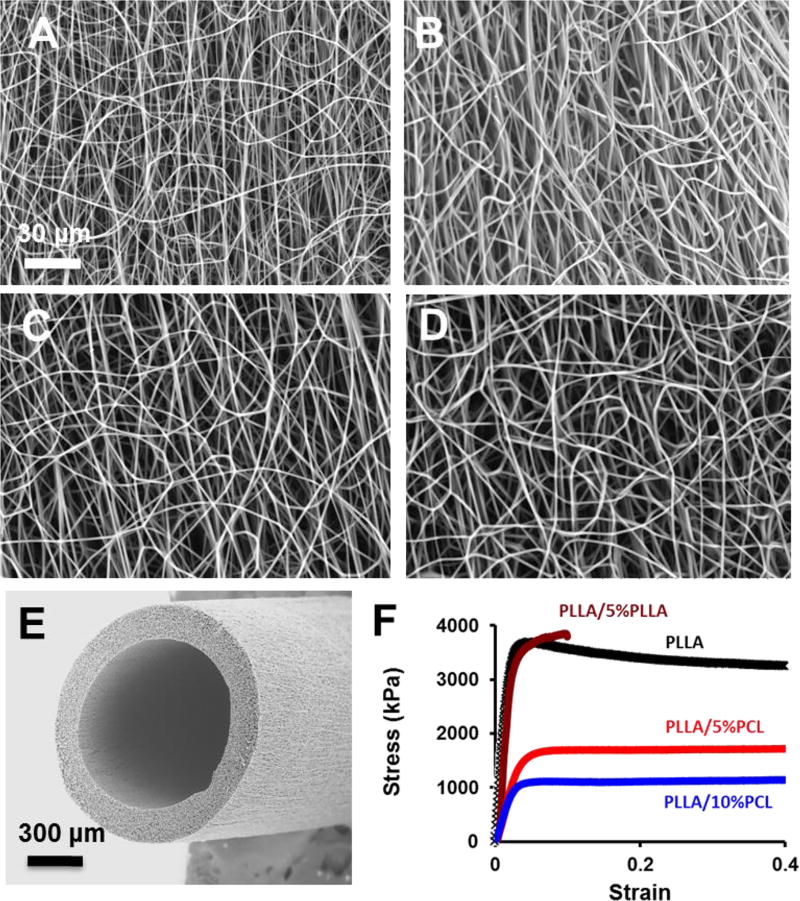
Electrospun scaffolds were fabricated by using PLLA as the structural polymer. To increase the number of end groups available for biomolecule attachment, low MW PCL or low MW PLLA was blended with a high MW PLLA. Four kinds of electrospun fibrous scaffolds were successfully fabricated by using the chosen polymer compositions: PLLA, PLLA/5%PLLA, PLLA/5%PCL, and PLLA/10%PCL (Fig. 1A–D). For all polymer groups, uniform fiber formation without beading was achieved using identical electrospinning parameters (i.e. voltage, flow rate and needle-to-collector distance). Fiber diameters were 866 ± 150 nm, 961 ± 265 nm, 926 ± 215 nm, and 982 ± 175 nm for PLLA, PLLA/5%PLLA, PLLA/5%PCL and PLLA/10%PCL scaffolds respectively. The pure PLLA samples had the pore sizes of sub-micrometers to several micrometers (Fig. 1A–B). PCL blending resulted in loose interconnected and hierarchically structured pores with sizes ranging from several micrometers to few hundreds of micrometers as shown in Fig. 1B–D. The higher viscosity of PLLA/PCL electrospinning solution and immiscible phase separation between PLA and PCL might lead to larger fiber diameter and loose fiber stacking, which could enhance cell infiltration and scaffold remodeling. A vascular graft made from PLLA/5%PCL is exemplified in Fig. 1E.
Figure 1.
Structural and mechanical characterization of micro/nanofibrous scaffolds. (A–D) Scanning electron microscopic (SEM) images of the electrospun scaffolds with PLLA (A), PLLA/5%PLLA (B), PLLA/5%PCL (C), PLLA/10%PCL (D). (E) Representative SEM image of an electrospun vascular graft with PLLA/5%PCL. (F) Stress-strain curves of electrospun scaffolds. The scale bar indicates 30 µm (A through D), and 300 µm (E).
3.2 Mechanical Properties of Blended Electrospun Scaffolds
Uniaxial tensile testing of electrospun scaffolds was performed to investigate how the incorporation of a low MW polymer would affect the bulk mechanical properties such as elastic modulus, UTS, and strain at failure (Fig 1F). In general, PLLA is stiffer, and PCL is elastic and more flexible, which may help improve the mechanical property of the scaffolds. The elastic modulus of the electrospun scaffolds was 170 ± 7.6 MPa, 180 ± 10.1MPa, 68 ± 8.7 MPa, and 33 ± 7.0 MPa for PLLA, PLLA/5%PLLA, PLLA/5%PCL and PLLA/10%PCL polymer compositions respectively. There was no difference between the modulus of PLLA and PLLA/5%PLLA scaffolds, suggesting that the addition of 5% LMW-PLLA into the polymer blend had no significant effect on elastic modulus. The addition of LMW-PCL resulted in a significant decrease in elastic modulus, which was still higher than native artery. Reduction in elastic modulus was more evident when the amount of blended LMW-PCL was increased from 5% (w/v) to 10% (w/v) (p<0.001). From physical examination, grafts became more flexible and kink-resistant with the addition of LMW-PCL. The UTS was 3.7 ± 0.2 MPa, 3.8 ± 0.3 MPa, 1.8 ± 0.1 MPa, and 1.0 ± 0.1 MPa for PLLA, PLLA/5%PLLA, PLLA/5%PCL and PLLA/10%PCL polymer compositions respectively. There was no difference in UTS between PLLA and PLLA/5%PLLA scaffolds. However, addition of 5% (w/v) LMW-PCL reduced UTS by nearly 50% relative to PLLA. When the concentration of LMW-PCL was increased to 10% (w/v), UTS decreased by approximately 75%.
PLLA scaffolds had a strain-at-failure of approximately 40% elongation. Addition of LMW-PLLA significantly reduced strain-at-failure, and the abrupt fracture of PLLA/5%PLLA scaffolds occurred at less than 10% elongation. This was predictable because the molecular weight of LMW PLLA (2000 Da) was lower than the critical molecular weight (~16 000 Da) for fiber entanglement [19]. Since abrupt fracture at low levels of strain is highly undesirable for a vascular graft design, PLLA/5%PLLA scaffolds were excluded from the remaining experiments. The addition of LMW-PCL increased strain-to-failure of PLLA/5%PCL and PLLA/10%PCL to more than 75% elongation.
PLLA/5%PCL scaffolds had an elastic modulus similar to ePTFE and a UTS in the range of native arteries (Table 1). Thus, PLLA/5%PCL was chosen for the fabrication of tubular grafts for vascular implantation (Fig. 1E). It is also worth mentioning, that since PLLA/10%PCL had a UTS similar to the lower limit of that found in native arteries, as a factor of safety, PLLA/5%PCL was used instead.
Table 1.
Mechanical properties of the electrospun scaffolds.
3.3 Heparin Immobilization
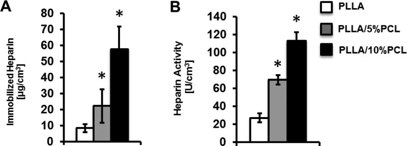
To investigate the effect of low MW polymer addition on biomolecule coupling capacity, we measured the density of immobilized heparin in PLLA, PLLA/5%PCL and PLLA/10%PCL scaffolds (Fig. 2A). The amount of immobilized heparin in PLLA, PLLA/5%PCL and PLLA/10%PCL scaffolds was 8.4, 22.2 and 57.7 µg/cm3 respectively. Thus, a significant increase in immobilized heparin density could be achieved when LMW-PCL was blended into the polymer solution prior to electrospining. The density of heparin immobilization continued to increase as the concentration of LMW-PCL was increased from 5% (w/v) (PLLA/5%PCL) to 10% (w/v) (PLLA/10%PCL).
Figure 2.
Characterization of immobilized heparin on materials. (A) Density of immobilized heparin in electrospun scaffolds with PLLA, PLLA/5%PCL and PLLA/10%PCL. (B) Anticoagulant activity of immobilized heparin in the electrospun scaffolds with PLLA, PLLA/5%PCL and PLLA/10%PCL.
3.4 Antithrombogenic Activity of Immobilized Heparin
The thrombin binding activity of immobilized heparin was assessed for PLLA, PLLA/5%PCL, and PLLA/10%PCL scaffolds (Fig. 2B). The activity of immobilized heparin on PLLA, PLLA/5%PCL and PLLA/10%PCL scaffolds was 27.3, 69.6, and 112.6 NIH Units/cm3 respectively. No significant difference in activity was found among any of the non-heparin-modified scaffolds (data not shown). This result confirmed that immobilized heparin retained anti-thombogenic activity. PLLA/5%PCL and PLLA/10%PCL scaffolds exhibited an increase in anti-thrombogenic activity, which was consistent with the increase in heparin density in these scaffolds.
3.5 VEGF Immobilization and Release
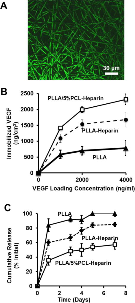
VEGF was immobilized to non-heparin-modified PLLA (PLLA), heparin-modified PLLA (PLLA-Heparin) and heparin-modified PLLA/5%PCL (PLLA/5%PCL-Heparin) scaffolds. Heparin specific immobilization of VEGF to electrospun scaffolds was confirmed by immunostaining, as exemplified in Fig. 3A.
Figure 3.
VEGF immobilization and release from electrospun scaffolds. (A) Immunostaining of bound VEGF on heparin modified electrospun fibers. (B) Density of immobilized VEGF vs input VEGF concentration for the electrospun scaffolds with untreated PLLA, heparin-modified PLLA and heparin modified PLLA/5%PCL. (C) Release of VEGF over 7 days from the electrospun scaffolds with untreated PLLA, heparin-modified PLLA and heparin-modified PLLA/5%PCL. Results for untreated PLLA and PLLA/5%PCL were similar, and thus only untreated PLLA is shown.
We also determined the density of immobilized VEGF in PLLA, PLLA-Heparin and PLLA/5%PCL-Heparin scaffolds as a function of initial VEGF loading concentration (Fig. 3B). The density of immobilized VEGF was significantly greater on PLLA/5%PCL-Heparin scaffolds than PLLA-Heparin scaffolds for all loading concentrations of VEGF (p<0.05). The amount of immobilized VEGF was significantly greater on both heparin-modified scaffolds than on untreated PLLA scaffolds at all loading concentrations. The amount of VEGF on untreated PLLA and PLLA/5%PCL scaffolds was similar, thus only untreated PLLA is shown.
Release of VEGF from PLLA, PLLA-Heparin and PLLA/5%PCL-Heparin was measured over a time period of 7 days (Fig. 3C). Approximately 83% of the immobilized VEGF was lost from untreated PLLA scaffolds after 1 day. Heparin modification of PLLA reduced the initial burst release of VEGF to 60% after 1 day. The burst release of VEGF from PLLA/5%PCL-Heparin scaffolds, which contained approximately 3-times more bound heparin, was further reduced to approximately 40% of the initial concentration. After 7 days, all VEGF had been released from untreated PLLA scaffolds, while PLLA-Heparin scaffolds retained approximately 15% of the initially bound VEGF. Retention of VEGF on PLLA/5%PCL scaffolds was significantly greater after 7 days, with nearly 50% of the initially bound VEGF still remaining. Release of VEGF from untreated PLLA and PLLA/5%PCLL was similar at all time points, thus only release information for PLLA is shown.
3.6 In vivo Patency of Bioactive Electrospun Vascular Grafts
Using PLLA/5%PCL, untreated, heparin-modified and VEGF-modified scaffolds were fabricated and implanted into rats as vascular grafts to test their performance. VEGF significantly increased the patency of vascular grafts after 1-month. After 1-month, 6 of 11 (55%) untreated grafts, 7 of 11 (64%) heparin-modified grafts, and 10 of 11 (88%) VEGF-modified grafts were patent.
3.7 Endothelialization, Cellular infiltration and Matrix Remodeling of Vascular Grafts
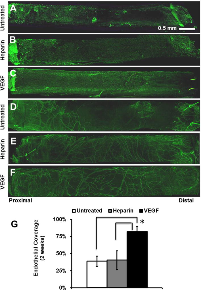
We postulated that the improved patency of VEGF-modified grafts could be attributed to the enhanced endothelialization by VEGF at earlier time points. Therefore, electrospun vascular graft explants were stained for the EC surface marker CD31 to assess the degree of endothelialization after 2-weeks (Fig. 4A–C). VEGF immobilization significantly increased endothelialization on the inner surface. VEGF-modified grafts had 82% EC coverage after 2-weeks, which was approximately twice as much coverage found on both untreated and heparin-modified grafts which had 39% and 40% EC coverage respectively (Fig. 4G). After 2-weeks, substantial angiogenesis was observed in the outer layer of all grafts (Fig 4D–F), with more microvessels around the grafts treated with heparin or heparin/VEGF, but no obvious differences were observed for these two treatments. The presence of newly formed microvessels suggests that the implanted grafts had been effectively integrated with the host tissues.
Figure 4.
Endothelialization and angiogenesis in vascular grafts at 2 weeks post-implantation. The grafts were stained for EC marker CD31. (A–C) EC coverage on the inner surface (lumen) of the grafts: (A) untreated, (B) heparin-modified, and (C) VEGF-modified. (D–F) ECs of microvessels on the outer surface of the grafts: (D) untreated, (E) heparin-modified, and (F) VEGF-modified. (G) Quantification of EC coverage on the whole inner surface of grafts at 2 weeks post-implantation. Scale Bar = 0.5 mm.
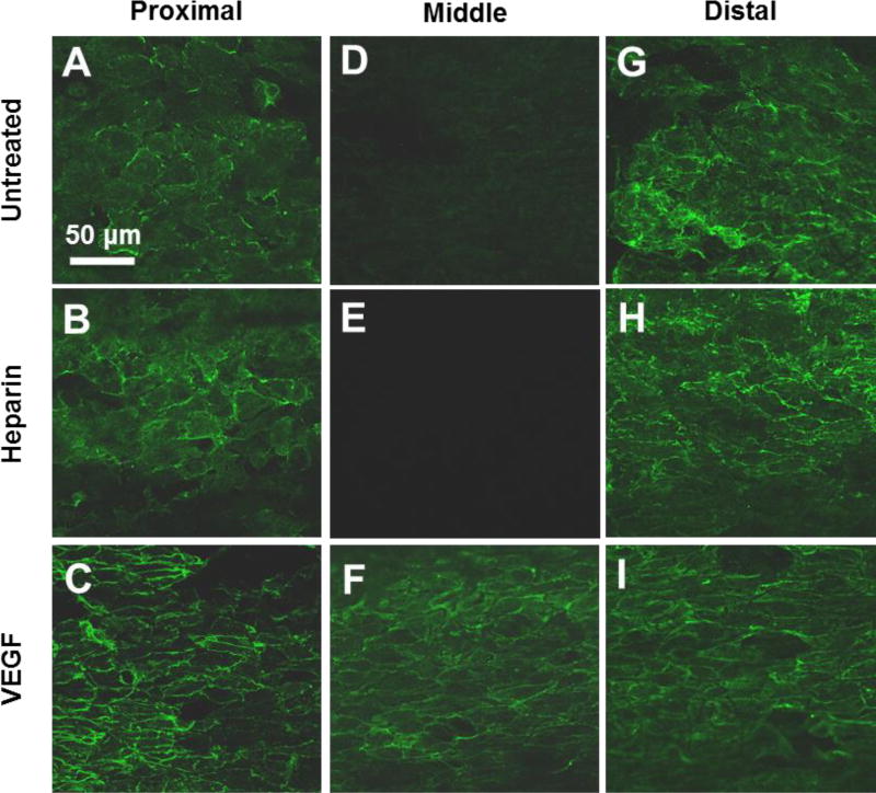
Close examination of the luminal surface showed that the major difference in endothelialization was in the middle segment of the grafts at 2 weeks (Fig. 5). Since ECs might migrate into the grafts from the adjacent carotid artery at the two ends, there was no significant difference in endothelialization near the proximal and distal ends of the grafts (Fig. 5A–C, G–I). In contrast, VEGF-modified grafts enhanced endothelialization in the middle segment of the grafts, possibly by increasing EC proliferation and migration. In addition to having more luminal coverage at 2-weeks, ECs on VEGF-modified grafts were more elongated and had morphology similar to that normally observed in the native endothelium (Fig. 5D–F).
Figure 5.
High magnification images of ECs on the inner surface of the vascular grafts at 2 weeks post implantation. The inner surfaces of the grafts were stained for EC surface marker CD31. Representative images of inner surface were taken from proximal, middle and distal graft segments. Scale Bar = 50 µm.
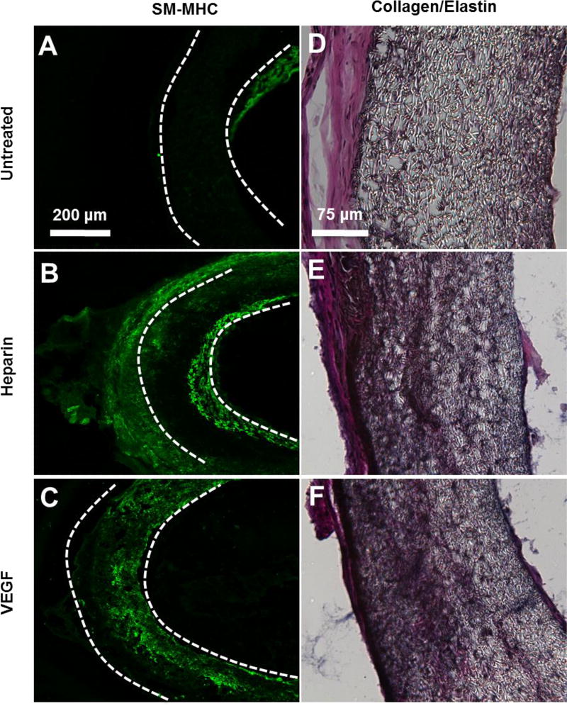
The remodeling of the vascular graft wall after 1-month was also analyzed (Fig. 6A–F). MHC+ SMCs were found within the wall of heparin-modified and VEGF-modified grafts (Fig. 6B–C). MHC+ cells were also present within the neotissue that surrounded most but not all grafts. Small traces of intimal hyperplasia were observed in a few untreated grafts at 1-month, as demonstrated by the presence of SMCs in the neointima (Fig. 6A).
Figure 6.
SMCs and collagen/elastin deposition in electrospun vascular grafts at 1 month post-implantation. (A–C) Cross-sectional staining of SM-MHC for SMCs in the vascular grafts. (D–F) Collagen and elastin deposited in the grafts were examined by using Verhoeff’s stain. Collagen is shown in pink, Elastin is shown in black. The scale bar indicated are 200 µm (A through C), and 75 µm (D through F).
The extent of matrix deposition (collagen and elastin) within the graft was assessed 1-month after the implantation (Fig. 6D–F). Untreated grafts had minimal matrix deposition within the graft. In contrast, extensive matrix deposition was found within both heparin-modified and VEGF-modified grafts at 1-month. All grafts, untreated, heparin-modified and VEGF-modified, were surrounded by an outer layer of neotissue. The thickness of surrounding neotissue varied and did not appear to be dependent on the type of graft treatment used in this study.
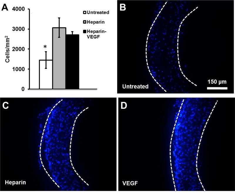
The effect of heparin and VEGF treatment on total cellular infiltration into electrospun grafts after implantation was assessed at 1-month (Fig. 7). Cellular infiltration was significantly greater for heparin-modified and VEGF-modified grafts, compared to untreated grafts. Some of the cells found within the wall of heparin-modified and VEGF-modified grafts are positive for MHC, as shown in Fig 6.
Figure 7.
Cell infiltration into electrospun vascular grafts at 1 month post-implantation. Nuclei are stained by DAPI. (A) Cell density within the graft was quantified. (B–D) Cross-sections of explanted electrospun vascular grafts 1 month post-implantations. The boundary of the graft is marked by dashed lines. Scale bar = 150 µm.
4. Discussion
Our objective was to create bioactive vascular grafts using electrosnpun fibers with the capability to accelerate endothelializaton and direct vascular cellularization in situ. In this study, we developed a method to significantly increase the surface conjugation capacity of an electrospun biodegradable polymer, HMW-PLLA, by blending with a low MW polymer prior to electrospinning. Covalent attachment of biomolecules to PLLA or PCL is accomplished by the conjugation to end groups. The addition of LMW-PCL increases the density of available end groups and results in the increased heparin conjugation capacity observed in this study. The morphology of electrospun HMW-PLLA fibers was not affected by the addition of LMW-PCL or LMW-PLLA, and the addition of either low MW polymer (LMW-PCL or LMW-PLLA) did not affect the ability of blended polymers to form fibers under identical electrospinning conditions, which makes this technique simple and versatile. It is interesting that blending PCL increased the pore size between micro/nanofibers, which may facilitate cell information and scaffold remodeling. As an elastic polymer, PCL decreased the stiffness of PLLA grafts, and increased the deformability and the strain and the failure, which is a significant improvement of mechanical property.
The increase of heparin amount conjugated to the scaffolds indeed increased the loading capacity of VEGF in the scaffolds. In addition, heparin modification reduced the initial burst release of VEGF from electrospun PLLA scaffolds. PLLA/5%PCL scaffolds, which had significantly greater heparin conjugation capacity, further reduced the initial burst of VEGF. One explanation is that the increase of heparin on the surface of electrospun fibers provides more stable binding sites for VEGF. VEGF modification enhanced endothelialization of electrospun vascular grafts at 2-weeks, and also improved graft patency at 1-month. Endothelialization may have occurred through a combination of proposed mechanisms including trans-anastomotic migration, capillary in growth and adhesion/differentiation/proliferation of circulating EC progenitors [10, 22]. To distinguish the source of ECs during regeneration, further investigations are needed. Achieving full endothelialization has been an extensive pursuit within the field of vascular tissue engineering. Previous studies have shown VEGF treated grafts enhance endothelialization but also at the cost of increasing inward remodeling from intimal hyperplasia [23,24]. In contrast, the presence of intimial hyperplasia was not observed in our study of VEGF treated grafts.
In addition to its an anticoagulation capability, heparin has been shown to inhibit SMC migration, neointimal formation and restenosis following vascular injury. Thus, heparin immobilization on the surface of synthetic matrices is a common approach to improve vascular graft functions [25]. In our study, we found cellular infiltration was significantly greater for heparin-modified and VEGF-modified electrospun grafts, compared to untreated grafts (Fig. 7). This observation is consistent with our previous findings that heparin modification of nanofibers promotes cell infiltration (not SMC-specific) into 3-D scaffolds in vivo [11, 26]. This enhanced cell infiltration may be related to the presence of heparin throughout the wall of the grafts and the charge/water retaining capability of heparin. The infiltrated cells in the vascular grafts may include immune cells, progenitors and fibroblasts [27]. Interestingly, in our previous study, we have shown that SMC progenitors, rather than mature SMCs, are recruited into the graft and that these progenitors gradually differentiated into SMCs [8], which is not in conflict with the inhibitory effect of heparin on SMC migration.
Small animal model with rats was used in this study, due to their low cost and the ease of care. Small animals have different circulatory system, vessel size, endothelialization rates and thrombogenicity to that of humans [28]. Therefore, it is crucial to investigate the graft endothelialization and the safety of surgeries in large animals, such as pigs, sheep and nonhuman primates, possessing similarities to human physiology, which should be addressed in future studies.
In conclusion, bioactive electrospun grafts have the potential to serve as a platform for in situ vascular tissue engineering. The capacity to couple biomolecules to the surface of bioresorbable electrospun materials can be significantly increased through blending of low MW polymers prior to electrospinning. This simple blending method can be used for other applications where a greater density of immobilized biomolecules on electrospun polymers is desirable. The low MW polymer blending method developed in this study may have wide applications in the fabrication of electrospun polymer scaffolds for tissue regeneration.
Acknowledgments
This study was supported in part by grants from National Institutes of Health (EB012240, HL083900, HL117213, HL121450 and predoctoral fellowship HL094162-04), the Ford Foundation (JH) and the Siebel Scholars Foundation (JH). We also would like to thank Dr. Nikita Derugin at the University of California, San Francisco for his assistance in animal surgery and Surya Kotha and Kellen Chen for their help during graft fabrication and histological analysis.
References
- 1.Huynh T, Abraham G, Murray J, Brockbank K, Hagen P, Sullivan S. Remodeling of acellular collagen graft into a physiologically responsive neovessel. Nature Biotechnology. 1999;17:1083–6. doi: 10.1038/15062. [DOI] [PubMed] [Google Scholar]
- 2.Nerem RM, Seliktar D. VASCULAR TISSUE ENGINEERING. Annual Review of Biomedical Engineering. 2001;3:225–43. doi: 10.1146/annurev.bioeng.3.1.225. [DOI] [PubMed] [Google Scholar]
- 3.Tomizawa Y. Vascular prostheses for aortocoronary bypass grafting: a review. Artificial organs. 1995;19:39–45. doi: 10.1111/j.1525-1594.1995.tb02242.x. [DOI] [PubMed] [Google Scholar]
- 4.Weinberg C, Bell E. A blood vessel model constructed from collagen and cultured vascular cells. Science. 1986 doi: 10.1126/science.2934816. [DOI] [PubMed] [Google Scholar]
- 5.L'Heureux N, Dusserre N, Konig G, Victor B, Keire P, Wight TN, et al. Human tissue-engineered blood vessels for adult arterial revascularization. Nat Med. 2006;12:361–5. doi: 10.1038/nm1364. [DOI] [PMC free article] [PubMed] [Google Scholar]
- 6.Gong Z, Niklason LE. Small-diameter human vessel wall engineered from bone marrow-derived mesenchymal stem cells (hMSCs) The FASEB Journal. 2008;22:1635–48. doi: 10.1096/fj.07-087924. [DOI] [PMC free article] [PubMed] [Google Scholar]
- 7.Hashi CK, Zhu Y, Yang GY, Young WL, Hsiao BS, Wang K, et al. Antithrombogenic property of bone marrow mesenchymal stem cells in nanofibrous vascular grafts. Proceedings of the National Academy of Sciences. 2007;104:11915. doi: 10.1073/pnas.0704581104. [DOI] [PMC free article] [PubMed] [Google Scholar]
- 8.Yu J, Wang A, Tang Z, Henry J, Li-Ping Lee B, Zhu Y, et al. The effect of stromal cell-derived factor-1α/heparin coating of biodegradable vascular grafts on the recruitment of both endothelial and smooth muscle progenitor cells for accelerated regeneration. Biomaterials. 2012;33:8062–74. doi: 10.1016/j.biomaterials.2012.07.042. [DOI] [PMC free article] [PubMed] [Google Scholar]
- 9.Wu W, Allen RA, Wang Y. Fast-degrading elastomer enables rapid remodeling of a cell-free synthetic graft into a neoartery. Nat Med. 2012;18:1148–53. doi: 10.1038/nm.2821. [DOI] [PMC free article] [PubMed] [Google Scholar]
- 10.Li S, Sengupta D, Chien S. Vascular tissue engineering: from in vitro to in situ. Wiley Interdiscip Rev Syst Biol Med. 2014;6:61–76. doi: 10.1002/wsbm.1246. [DOI] [PubMed] [Google Scholar]
- 11.Kurpinski KT, Stephenson JT, Janairo RRR, Lee H, Li S. The effect of fiber alignment and heparin coating on cell infiltration into nanofibrous PLLA scaffolds. Biomaterials. 2010;31:3536–42. doi: 10.1016/j.biomaterials.2010.01.062. [DOI] [PMC free article] [PubMed] [Google Scholar]
- 12.Patel S, Kurpinski K, Quigley R, Gao H, Hsiao BS, Poo MM, et al. Bioactive nanofibers: synergistic effects of nanotopography and chemical signaling on cell guidance. Nano Lett. 2007;7:2122–8. doi: 10.1021/nl071182z. [DOI] [PubMed] [Google Scholar]
- 13.Hasan A, Memic A, Annabi N, Hossain M, Paul A, Dokmeci MR, et al. Electrospun scaffolds for tissue engineering of vascular grafts. Acta Biomater. 2014;10:11–25. doi: 10.1016/j.actbio.2013.08.022. [DOI] [PMC free article] [PubMed] [Google Scholar]
- 14.Pektok E, Nottelet B, Tille J-C, Gurny R, Kalangos A, Moeller M, et al. Degradation and healing characteristics of small-diameter poly(ε-Caprolactone) vascular grafts in the rat systemic arterial circulation. Circulation. 2008;118:2563–70. doi: 10.1161/CIRCULATIONAHA.108.795732. [DOI] [PubMed] [Google Scholar]
- 15.Barrera DA, Zylstra E, Lansbury PT, Langer R. Copolymerization and degradation of poly(lactic acid-co-lysine) Macromolecules. 1995;28:425–32. [Google Scholar]
- 16.Hashi CK, Derugin N, Janairo RRR, Lee R, Schultz D, Lotz J, et al. Antithrombogenic modification of small-diameter microfibrous vascular grafts. Arteriosclerosis, Thrombosis, and Vascular Biology. 2010;30:1621–7. doi: 10.1161/ATVBAHA.110.208348. [DOI] [PMC free article] [PubMed] [Google Scholar]
- 17.Smith PK, Mallia AK, Hermanson GT. Colorimetric method for the assay of heparin content in immobilized heparin preparations. Anal Biochem. 1980;109:466–73. doi: 10.1016/0003-2697(80)90679-x. [DOI] [PubMed] [Google Scholar]
- 18.Chandler WL, Solomon DD, Hu CB, Schmer G. Estimation of surface-bound heparin activity: a comparison of methods. J Biomed Mater Res. 1988;22:497–508. doi: 10.1002/jbm.820220606. [DOI] [PubMed] [Google Scholar]
- 19.Cooper-White JJ, Mackay ME. Rheological properties of poly(lactides). Effect of molecular weight and temperature on the viscoelasticity of poly(l-lactic acid) J Polym Sci Pol Phys. 1999;37:1803–14. [Google Scholar]
- 20.Catanese J, Cooke D, Maas C, Pruitt L. Mechanical properties of medical grade expanded polytetrafluoroethylene: The effects of internodal distance, density, and displacement rate. Journal of Biomedical Materials Research. 1999;48:187–92. doi: 10.1002/(sici)1097-4636(1999)48:2<187::aid-jbm13>3.0.co;2-m. [DOI] [PubMed] [Google Scholar]
- 21.Fung YC. Biomechanics Circulation. 2. Springer; 1996. [Google Scholar]
- 22.Li S, Henry JJD. Nonthrombogenic Approaches to Cardiovascular Bioengineering. Annual Review of Biomedical Engineering. 2011;13:451–75. doi: 10.1146/annurev-bioeng-071910-124733. [DOI] [PubMed] [Google Scholar]
- 23.Walpoth BH, Zammaretti P, Cikirikcioglu M, Khabiri E, Djebaili MK, Pache J-C, et al. Enhanced intimal thickening of expanded polytetrafluoroethylene grafts coated with fibrin or fibrin-releasing vascular endothelial growth factor in the pig carotid artery interposition model. J Thorac Cardiovasc Surg. 2007;133:1163–70. doi: 10.1016/j.jtcvs.2007.01.029. [DOI] [PubMed] [Google Scholar]
- 24.Luong-Van E, Grøndahl L, Chua KN, Leong KW, Nurcombe V, Cool SM. Controlled release of heparin from poly(epsilon-caprolactone) electrospun fibers. Biomaterials. 2006;27:2042–50. doi: 10.1016/j.biomaterials.2005.10.028. [DOI] [PubMed] [Google Scholar]
- 25.Murugesan S, Xie J, Linhardt RJ. Immobilization of heparin: Approaches and applications. Curr Top Med Chem. 2008;8:80–100. doi: 10.2174/156802608783378891. [DOI] [PMC free article] [PubMed] [Google Scholar]
- 26.Janairo RRR, Henry JJD, Lee BLP, Hashi CK, Derugin N, Lee R, et al. Heparin-Modified Small-Diameter Nanofibrous Vascular Grafts. Ieee T Nanobiosci. 2012;11:22–7. doi: 10.1109/TNB.2012.2188926. [DOI] [PubMed] [Google Scholar]
- 27.Udelsman BV, Maxfield MW, Breuer CK. Tissue engineering of blood vessels in cardiovascular disease: moving towards clinical translation. Heart. 2013;99:454–60. doi: 10.1136/heartjnl-2012-302984. [DOI] [PubMed] [Google Scholar]
- 28.Pashneh-Tala S, MacNeil S, Claeyssens F. The Tissue-Engineered Vascular Graft-Past, Present, and Future. Tissue Eng Part B-Re. 2016;22:68–100. doi: 10.1089/ten.teb.2015.0100. [DOI] [PMC free article] [PubMed] [Google Scholar]


