Abstract
Hemodynamic recording during interventional cardiovascular procedures is essential for procedural guidance, monitoring patient status, and collection of diagnostic information. Recent advances have made interventions guided by magnetic resonance imaging (MRI) possible and attractive in certain clinical scenarios. However, in the MRI environment, electromagnetic interference (EMI) can cause severe distortions and artifacts in acquired hemodynamic waveforms. The primary aim of this paper was to develop and validate a system to minimize EMI on electrocardiogram (ECG) and invasive blood pressure (IBP) signals. A system was developed which incorporated commercial MRI compatible ECG leads and pressure transducers, custom electronics, user interface, and adaptive signal processing. Measurements were made on pediatric patients (N = 6) during MRI-guided catheterization. Real-time interactive scanning, which is known to produce significant EMI due to fast gradient switching and varying imaging plane orientations, was selected for testing. The effectiveness of the adaptive algorithms was determined by measuring the reduction of noise peaks, amplitude of noise peaks, and false QRS triggers. During real-time gradient-intensive imaging sequences, peak noise amplitude was reduced by 80% and false QRS triggers were reduced to a median of 0. There was no detectable interference on the IBP channels. A hemodynamic recording system front-end was successfully developed and deployed, which enabled high-fidelity recording of ECG and IBP during MRI scanning. The schematics and assembly instructions are publicly available to facilitate implementation at other institutions. Researchers and clinicians are provided a critical tool in investigating and implementing MRI guided interventional cardiovascular procedures.
Keywords: Adaptive signal processing, biomedical electronics, biomedical equipment, biomedical signal processing, cardiology, catheterization, magnetic resonance imaging
We present a MRI-compatible ECG and IBP recording system and demonstrate its performance in investigational pediatric cardiovascular intervention procedures.
I. Introduction
During interventional cardiovascular procedures, vital signals such as electrocardiogram (ECG), invasive blood pressure (IBP), and peripheral oxygen saturation (SpO2) are recorded to provide diagnostic information, guide the procedure, and monitor patient status. Standard commercial systems for hemodynamic recording commonly used in X-ray angiography suites have workflow features which allow case annotation, continuous recording, and integration with the hospital’s information network.
Recent advances in technology have made magnetic resonance imaging (MRI) guided cardiovascular interventions possible and attractive in certain clinical scenarios. However, though hemodynamic recording is central to clinical care, the commercial systems available in the X-ray angiography suites do not provide MRI-compatible hemodynamic interfaces. The available MRI-compatible systems are limited to low-fidelity signal monitoring of 3-4 ECG leads plus two invasive blood pressure (IBP) channels. These systems are used as standalone platforms which provide basic patient monitoring functionality and may be used to generate triggers for cardiac-gated imaging. Few, if any, provide true diagnostic quality monitoring. While available MRI-compatible systems are safe to use in the MRI environment, the systems have limited ability to suppress the noise and distortion typically caused by the radiofrequency (RF) pulses and the large fluctuating magnetic fields of the gradient coils.
Noise and distortion can dominate ECG signals, preventing adequate patient monitoring and generating significant gating errors during imaging, breaking the necessary synchronization to the cardiac cycle. As noise and distortion vary widely from patient to patient, between adult and pediatric subjects, and from imaging sequence to imaging sequence, simple filters with fixed frequency responses have limited effectiveness. In addition, the gradient-induced noise has significant in-band components. This in-band noise tends to manifest as sharp spikes which can, at times, be difficult to distinguish from ECG R-peaks (Figures 5C, 6B, 10A) and severely impacts gating functionality. The magnetohydrodynamic (MHD) effect also causes severe distortion in the ECG signals (Figure 5B). Interventional cardiovascular imaging poses additional problems compared to standard cardiac imaging, as the imaging planes and other scans parameters are adjusted interactively during image acquisition as the catheters traverse the cardiovascular system. This real-time, interactive adjustment complicates the use of static algorithms which require training.
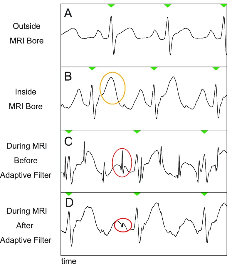
FIGURE 5.
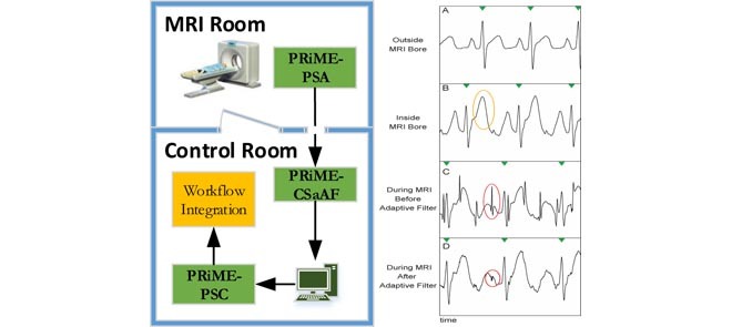
Example of removal of gradient-induced noise. Part A: A typical ECG signal of a patient outside the MRI bore. Part B: As the patient is moved into the bore, magnetohydrodynamic (MHD) effects cause various changes, such as an exaggerated T-wave (highlighted in yellow). Part C: the switching gradients of a typical real-time scan induce noise spikes in the ECG signal (highlighted in red). Part D: the adaptive filter of the PRiME system is able remove this gradient-induced noise spikes, however the MHD effects remain.
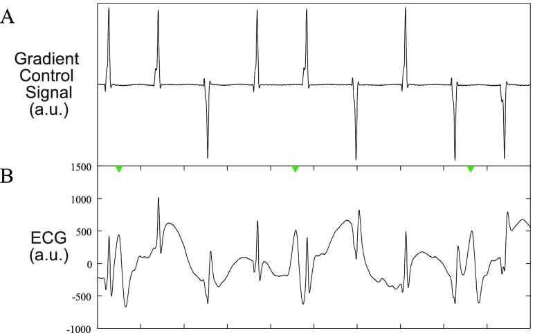
FIGURE 6.
Example of gradient effect on ECG. A: Typical gradient control signals from a real-time scan. All 3 gradients (X, Y, Z) are combined into a single signal for display purposes. The gradient control signals passed through a 5kHz low pass analog filter, sampled at 10kHz, and subsampled to 1kHz with an appropriate anti-aliasing filter to match the ECG sampling rate. B: a typical ECG signal during a real-time scan in which the gradient-induced noise is evident.
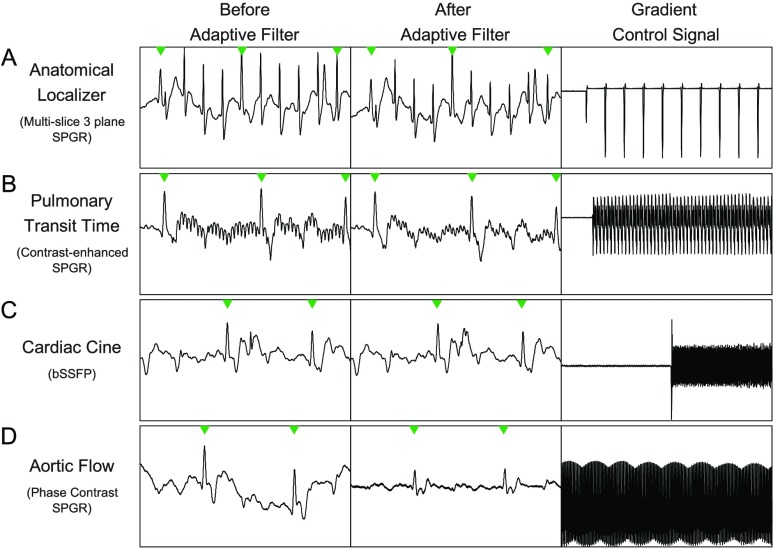
FIGURE 10.
Examples of non-real-time scans. In all examples, the first column is before the adaptive filter, the second column is after the adaptive filter, and the third columns is the sum of all the gradient control signals. Row A is a anatomical localizer scan, Row B, is a pulmonary transit time measurement scan, Row C is a 3 chamber cardiac view scan, and Row D is an aortic flow scan. More details on each scan can be found in the Results and Discussion section.
To realize the full potential of MRI-guided cardiovascular interventions, significant research and development must be performed to produce appropriate tools (such as catheters) and imaging sequences (to reduce heating effects and provide real-time imaging with sufficient contrast). Animal and human subjects are an important part of the investigational development of these tools. The nature of the interventional procedures requires hemodynamic recording to provide cardiovascular diagnosis and treatment. Researchers in MRI-guided cardiovascular interventions require a robust hemodynamic recording system to further research into other tools and novel procedures, in addition to requiring such a system as the procedures translate to clinical use [1].
Currently, there is no commercially available system (from large or small vendors) which meet the needs of the MRI-guided cardiovascular intervention research community. The lack of such a system is a limiting factor in translating new procedures and devices to clinical use. The goal of this work was to build on previous work [2] to develop a clinical system for hemodynamic monitoring in the MRI environment. We aimed to design and validate a system that: 1) minimizes MRI-induced noise through the design of front-end electronics, 2) dynamically corrects for noise spikes and other distortions cause by the MR imaging scans, 3) integrates with standard clinical workflow including interfacing to commercial hemodynamic recording systems used in X-ray angiography suites to enable the use of existing workflow features, and 4) consists of off-the-shelf components to facilitate replication and dissemination. As an additional constraint, focus was placed on quickly achieving a clinically usable system to allow existing patient populations to participate in investigational interventional procedures. The success of the system enabled research in a 39-patient pediatric study [3] and 102-patient adult study [4].
The PRiME system acquires 6-lead ECG and two channels of invasive blood pressure (IBP). In the MRI environment, the dominate noise sources are: 1) the static magnetic field which causes constant distortion (due to the MHD effect) to the ECG signal while the patient is inside the bore (Figure 5B), 2) the 64MHz radiofrequency (RF) pulses which, while out-of-band, can cause in-band noise as discussed later, and 3) noise induced by the kilohertz switching frequency of the magnetic gradient coils which causes spike-like noise in the ECG. While the ECG is heavily effected by all three noise sources, the IBP is only affected by the RF pulses. Proper circuity design (discussed later) is necessary and sufficient for eliminating the RF noise in the IBP signals. For the ECG, the gradient induced noise has a frequency bandwidth which effectively spans from DC to a few kHz, depending on the imaging sequence and parameters. Therefore, while proper circuitry design is necessary for eliminating the RF noise and minimizing the gradient-induced noise, circuitry design alone is not sufficient for eliminating all noise as a significant portion of the noise falls within the bandwidth of the ECG signal. As mentioned earlier, during an interventional procedure, the parameters for the imaging sequence will be varied which in turn affect the spectral distribution of the noise. Most importantly, while the gradient waveforms and spectra are known for any given imaging sequence, how those gradients induce noise is unknown. As mentioned earlier, even for a specific imaging sequence, the nature of the noise seen on the ECG signals will vary significantly from patient to patient, and for a given patient on different days. For some patients, there is little gradient-induced noise seen on the ECG signals, while other patients exhibit significant noise on the ECG signals. There is no known effective model for predicting the noise given a known set of parameters for the patient and imaging sequence. While the authors acknowledge this is an important area of research, we do not discuss it further in the manuscript.
The MHD effect is caused by charged ions in the blood flowing perpendicular to the static magnetic field, which generates a Hall potential across the vessel wall [5], [6]. This additional induced voltage can cause an elevation of the T wave in the observed ECG, as depicted in Figure 5B. In this work, the MHD effect was minimized by placing all ECG leads on the left side of the mid-line, on one side of the aorta. Though MHD can significantly distort the ECG waveforms and affect trigger generation, the non-linear nature of the distortion cannot be addressed by filtering, adaptive or otherwise. To increase the stability of trigger generation in the presence of MHD, the option to differentiate the ECG (or IBP) signals was added, with the goal of sharpening the QRS-complex more than the enhanced T-wave, and facilitating consistent trigger detection. Other researchers have developed approaches to suppress the MHD effect [7] or to estimate cardiac stroke volume [8], [9]. The severe distortion caused by the MHD effect prevents analysis comparing out-of-bore signals (i.e. clean ECG with no noise induced by the MRI environment) with ECG signal collected during scanning as the MHD effects dominates typical signal-to-noise ratio measurements.
To be used in a clinical interventional environment, the filtering and data processing must be done in real-time. The real-time requirement limits the complexity of the adaptive filter used and limits the use of algorithms which require training (which would need to be done on a per-patient basis), as the training could interrupt the clinical workflow.
II. Methods
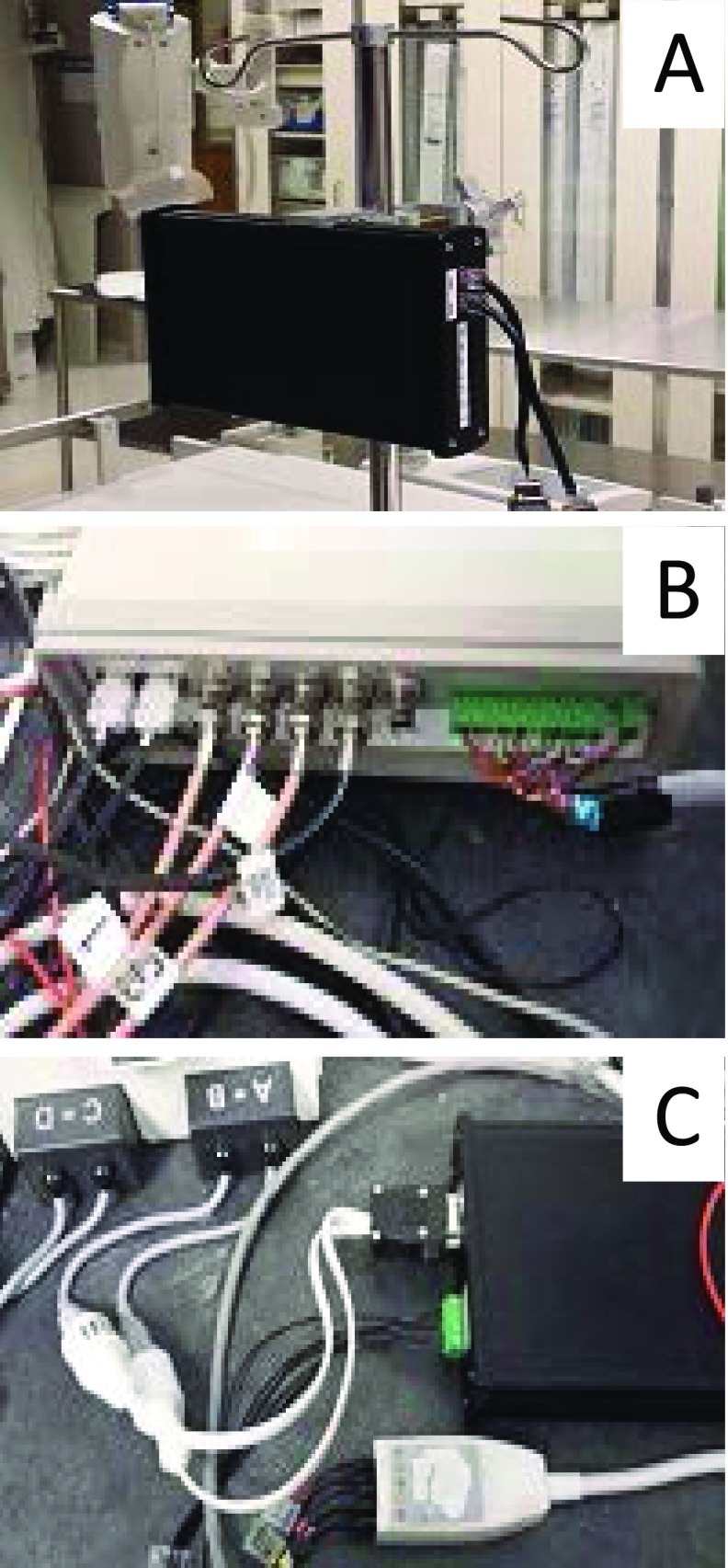
In this section, we describe the modules of the Physiological Recording in the MRI Environment (PRiME) system. Figure 1 shows how the PRiME modules integrate within the cardiovascular interventional workflow. The PRiME system consists of three modules: 1) the Physiological Signal Acquisition (PSA) module (Figure 2A) acquires the physiological signals, 2) the Control System and Adaptive Filter (CSaAF) module (Figure 2B) provides adaptive filtering of the signals from the PSA, and 3) the Physiological Signal Converter (PSC) module (Figure 2C) converts the digital signals from the CSaAF into an analog format compatible with commercial hemodynamic recording systems.
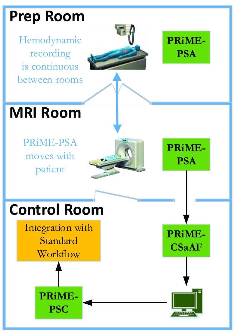
FIGURE 1.
Integration of the PRiME system with an interventional workflow. The PRiME system can begin monitoring the ECG and IBP signals during patient preparation and continues to monitor the patient through the transfer to the MRI room and during the MRI-guided intervention. Commercial hemodynamic recording systems common in a catheterization lab continuously receive the hemodynamic signals for integration with the standard interventional workflow.
FIGURE 2.
Photos of PRiME modules. A. PRiME-PSA (Physiological signal acquisition), B. PRiME-CSaAF (Control system and adaptive filter), C. PRiME-PSC (Physiological signal converter).
The PSA module, in addition to providing the transducer interface, pre-amplifier, and digitization also implements the out-of-band (compared to the ECG and IBP signals) noise filtering as discussed below. The out-of-band noise consists of RF interference (64MHz for a typical 1.5T clinical MRI system) and gradient-induced noise (varies according to the imaging sequence, but in the kHz range). The CSaAF module, specifically the adaptive filter, implements the in-band (considered < 50Hz) filtering which consists of gradient-induced noise. Due to the severity of the induced noise from both sources, the PSA module filters signals at a lower cutoff rate (<50Hz in the current implementation) than is desired to maintain complete ECG morphology.
In accordance with our goal of facilitating replication and dissemination, a detailed description of the PRiME system, parts list, assembly instructions, user manuals, and troubleshooting guides are posted on the web [10]. These license-free documents are designed to enable complete replication of the system described in this paper.
A. Physiological Signal Acquisition (PSA)
The PSA module provides the electronics necessary for ECG and IBP signal conditioning, including non-adaptive filtering and digitization. Sensors for ECG and invasive blood pressure connect directly to the PSA which is mounted on the patient table. MRI-compatible high impedance ECG leads (9218A, GE Healthcare, Milwaukee WI) and disposable IBP transducers (TruWave, Edwards Lifesciences Corp., Irvine, CA) are used. Each ECG lead set contains four leads, and two sets may be used jointly to connect the four limb electrodes plus three precordial electrodes. Custom interface cables [11] were constructed to connect the IBP transducers through RJ45 (Ethernet CAT5 style) connectors. Ideally, this cable length is minimized to reduce radiofrequency interference, but a longer cable may be used as needed. The PSA module is powered by a removable, rechargeable 3.7V lithium ion battery (CC2300, Accutronics, Staffordshire, UK) with an estimated 10 hours of use.
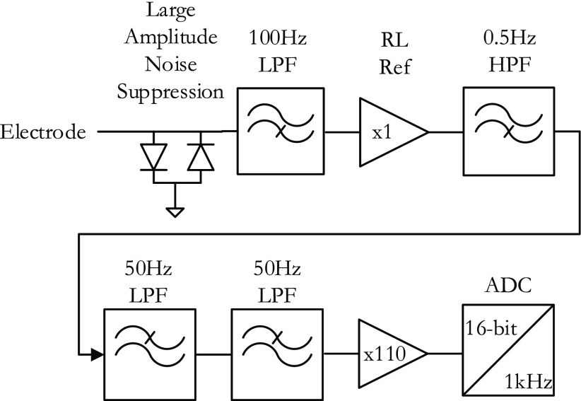
PRiME expects to interface with commercial hemodynamic recordings systems which in turn expect to interface directly to the individual lead wires. Therefore, PRiME treats all ECG electrode signals independently throughout analog processing and analog-to-digital conversion (ADC) (Figure 3). All signals (ECG and IBP) pass through a 1 uH RF choke to help suppress RF interference. In the first stage of analog circuitry, each ECG electrode signal is low-passed filtered (cutoff frequency  Hz) with a simple resistor-capacitor (RC) filter using high speed circuit components [12]. The high-speed circuit components are crucial for proper filtering of the high frequency gradient and RF noise which typical low frequency ECG circuit components do not tolerate [13]. In the second stage, the limb and precordial leads are first referenced to the right leg electrode, then passed through a high-pass RC filter (
 Hz), then a 2-stage low pass filter (Sallen-Key topology,
  Hz), and finally amplified (Gain = 110) before digitization. The 49 Hz cutoff points were chosen during initial experimentation as a tradeoff between eliminating high-frequency noise while preserving as much frequency content of the ECG as possible. The final gain stage is also configured for additional low-pass, anti-aliasing filter with cutoff of 482Hz.
FIGURE 3.
Components of the Physiological Signal Acquisition (PSA) module. The block diagram shows the signal flow from a single ECG electrode and is repeated for every electrode. A pair of diodes suppress large noise spikes before they saturate the inputs of any op-amps. The signal is then filtered (cutoff frequency fc = 100 Hz) using high-frequency components before being referenced to the right leg (RL) electrode. A high-pass filter blocks any DC component (fc = 50 Hz), and a 2-stage low pass filter further suppresses high frequency noise (fc = 50). The signal is amplified and converted to 16-bit data at a 1kHz sampling rate.
The differential IBP signals from the transducer are amplified using an instrumentation amplifier (AD620, Analog Devices, Norwood, AM) after passing through an RF interference filter [13]. An ADC (ADS1198, Texas Instruments, Dallas, TX) simultaneously digitizes all 8 signals (6 ECG, 2 IBP) with 16-bit precision at a 1 kHz sampling rate. The ADC serializes the digital output through an SPI (Serial Peripheral Interface) port. Fiber optic cable transceivers (AFBR-x62y, Avago, San Jose, CA) convert the four digital SPI electrical signals (i.e., clock, data in, data out, and data ready) to digital optical signals. The optical signals are routed via four 1mm plastic optical fibers (POF) out of the MRI suite through a waveguide to the PRiME Control System and Adaptive Filtering module (CSaAF).
B. Control System and Adaptive Filtering (CSaAF)
The CSaAF module interfaces with the PSA and PSC modules, implements the adaptive filtering algorithm, and connects with the computer which provides the user interface. Located in the MRI control room, the CSaAF consists of a single enclosure containing a field programmable gate array (FPGA) board (USB-7856R OEM, National Instruments, Austin, TX), microprocessor board (MPS-EXP430F5529LP, Texas Instruments, Dallas, TX), and custom electronics [14]. The CSaAF interfaces with a Windows-based computer running the LabVIEW (National Instruments, Austin, TX) programming environment. The microprocessor module acts as a command-and-control interface and outputs the data via an SPI interface to the FPGA system for further signal processing. The microprocessor module sets the initial PSA configuration (e.g., ADC initialization), detects and annunciates communication failure with the PSA (i.e., outputs a repeating series of pulses to clearly indicate lack of true signal), and generates test signals as necessary.
The MR imaging gradient control signals from the MRI system cabinets connect to the CSaAF via coaxial cables, and are reference inputs to the real-time adaptive filter implemented on the FPGA board. A custom LabVIEW program displays the ECG and IBP signals, and allows real-time control of the adaptive filter parameters [15]. The CSaAF also outputs a digital trigger signal based on any of the ECG or IBP signals, which can be used by the MRI scanner for gating or triggering. The triggering feature allows simple differentiation of the chosen trigger signal to help accentuate the R-peak from T-waves in cases in which the latter dominates due to magnetohydrodynamic distortion. Differentiation also sharpens the rising edge of an arterial pressure signal for more consistent triggering.
1). Adaptive Filter
The adaptive filter within the CSaAF module uses a Least-Means-Square (LMS) algorithm to reduce MRI gradient noise in signals acquired from the ECG leads. The IBP signals, which are not affected by the gradients, do not pass through the adaptive filter. The LMS algorithm provides real-time performance and can easily be implemented in the FPGA system. For this application, each ECG channel is comprised of three separate LMS filters, one corresponding to each gradient signal generated by the MRI system (Figure 4).
FIGURE 4.
The block diagram shows the adaptive filter signal flow for each ECG signal. The X, Y, Z gradients are sampled and used as the error signal for a least-mean-squares adaptive algorithm which dynamically alters the weights of a digital linear filter. The outputs of the three independent filters (one for each gradient) is then summed, and subtracted from the incoming ECG signal as the error signal.
The LMS filter consist of two parts, a Finite Impulse Response (FIR) digital filter and an adaptive algorithm to set the weights (i.e. the frequency response) of the FIR filter. The inputs to the adaptive filter are a primary signal (i.e., ECG) and three reference signals (i.e., gradient signals). The primary signal can be considered to consist of an ideal (desired) signal (which in the PRiME case is the ECG signal) with added noise signals. A reference signal is representative of an original source of noise, which in the PRiME case, is one of the gradient control signals. The gradient control signals are connected with coaxial cables to the CSaAF module, filtered with an analog 5kHz RC anti-aliasing filter, and digitized at a 10kHz sampling rate by the FPGA board. To match the sampling rate of the ECG signals from the PSA module, the digitized gradients signals are digitally filtered, and then subsampled to a 1kHz sampling rate. The LMS adaptive filter output is the difference between the primary signal and the combined filtered reference signals. This output signal feeds back into the adaptive algorithms to update the weights of the FIR filters, thus altering how the reference signals are filtered. The feedback mechanism will optimally filter the reference signals to closely match the actual noise (i.e., combined noise from all three gradient signals) in the primary signal, thus approximating the ideal signal (i.e., ECG) at the output. While the gradient control signals should be correlated with the gradient-induced noise, the actual shape and size of the gradient control signals do not accurately reflect the noise seen on the ECG signals. As mentioned earlier, there is no known effective model for how the gradients induce noise on the ECG, nor is the induced noise consistent from patient to patient.
Many different MRI acquisition sequences are implemented and used daily. Each sequence uses a unique set of gradient signals during the imaging procedure. To accommodate these variations, the user can set the length (i.e., number of taps) of the FIR filter and a scaling factor (i.e. beta parameter) that controls the magnitude of the updates to the FIR filter weights. Both parameters control how fast the algorithm minimizes the noise (i.e. convergence time), though certain combinations can cause the filter to become unstable, distorting the output through oscillations, saturation, and offsets. In typical use, the length of the FIR filter is maintained at 100 taps, while the scaling factor is adjusted between 1e-12 and 1e-8, depending on the severity of the induced noise. To simplify use for clinical staff, this scaling factor can be adjusted using a slider on the PRiME software application which indicates how much filtering is performed. The slider allows 4 settings: 1) a None setting (scaling factor = 0) which disables the filtering, 2) a Low setting (scaling factor = 1e-12), which is the default setting and the most commonly used, 3) a Med setting (scaling factor = 1e-10) for more aggressive filtering, and 4) a High setting (scaling factor = 1e-8) which is only occasionally used. The scaling factors for each setting were empirically determined during development as the most commonly used settings. The clinical staff can quickly increase the filtering to the next highest level until the noise is reduced to an acceptable level. More aggressive filtering (particularly the High setting) tends to distort the ECG as well, so the staff is instructed to only increase the filtering setting if necessary. The None setting is used for debugging, or in rare cases where the filter becomes unstable (e.g. Figure 7, Case 3).
FIGURE 7.
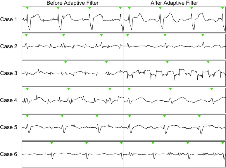
Example ECG segments of the 6 pediatric cases used to demonstrate the PRiME system. The first column shows the ECG segment before the adaptive filtering is applied, and the second column shows the same ECG segment after the adaptive filtering. In most cases, the adaptive filter improves the signal, but in some cases (3,6), the filter deteriorates the signal further due to an instability in the filter. In the last case (6), this was resolved by resetting the filter taps. In case 3, the instability may have been caused by gradient signal saturation in the PRiME system.
The PRiME software application provides a secondary screen which displays the current filter weights for debugging purposes. This screen also provides finer control over the scaling factor for testing and evaluation purposes. The software does not currently provide a method to save the filter weights for later analysis. While the authors acknowledge the necessity of this information for evaluating filter performance and future improvements, the real-time constraints of the system required tradeoffs on the amount of data that could be transferred and stored.
After the adaptive filter, the CSaAF module converts the ECG and IBP digitized signals to pulse-width-modulated (PWM) signals which are transferred over twisted-pair electrical cables to the PSC module, which may be located in either the control room or X-ray suite. PWM signals are relatively tolerant to electrical noise pickup when long cables are needed to connect the CSaAF and PSC modules.
C. Physiological Signal Converter (PSC)
The PSC module converts the digital output of the CSaAF module into an analog format compatible with commercial hemodynamic recording systems. The PSC module converts the unipolar digital signals to bipolar signals, demodulates the signals using a 2-stage Sallen-Key filter, and, finally, attenuates the analog signals to transducer-level voltages [16]. These signals connect to the commercial hemodynamic recording system (e.g., SENSIS, Siemens Medical Systems, or MacLab, GE), which enables the operators to use the same recording system employed for conventional X-ray guided procedures. The recording systems offer important features, including case annotation and connection to the hospital information network. Custom adapter cables [11] are required to connect the PSC output signals to the analog input connectors of the commercial hemodynamic recording systems.
D. Human Subject Studies
The PRiME system was tested in one adult patient and six pediatric patients undergoing MRI-guided right heart catheterization. The research studies were approved by the local Institutional Review Boards of the respective institutions (adults: National Heart and Lung Institute, pediatric: Children’s National Medical Center). Written informed consent to participate was obtained from all subjects or guardians. All MRI scans were conducted on at 1.5T (Aera, Siemens Medical System) equipped with high performance gradient hardware with 45 mT/m maximum amplitude and 200 mT/m/ms maximum slew rate. Subjects were scanned using 3 6-element torso coils placed on the anterior and posterior chest.
Unless otherwise noted, real-time MRI scans used a balanced steady-state free precession (bSSFP) acquisition with flow-sensitive dark blood magnetization preparation (flip angle = 45°, TE/TR = 1.29/2.6 ms, FOV = 400 mm, slice thickness = 8 mm, number of interleaved slices = 1-3 (oblique image orientations), in-plane resolution:  mm, parallel imaging acceleration factor = 2, bandwidth = 1008 Hz/pixel, [5]). The interactive bSSFP scan allows slice orientation to be changed on the fly, which can affect the nature of the gradient interference noise on the ECG signals.
E. Patients
Adult and pediatric patients were studied as part of a MRI-guided right heart catheterization protocol. ECG and IBP data was recorded during the procedure. IBP was measured in the femoral artery through a sheath and various chambers on the right side of the heart through a balloon wedge end-hole catheter (7 Fr Teleflex, Arrow, Limerick, PA). ECG data was recorded during real-time interactive scanning, function studies with cine imaging, and flow measurements with 2D phase contrast imaging with spoiled gradient echo.
F. Data Analysis
Analysis of how the complete PRiME system performs is complicated by the inability to simultaneously acquire corrupted and non-corrupted ECG signals in an MRI environment. The amplitude of the unfiltered noise (from both the RF pulses and gradients) is on the order of volts to tens of volts, while the ECG is less than 5 mV. The large dynamic range and inherent filtering in any circuitry used prevents the direct acquisition of the signals for comparison. The gradients only appear to induce noise on the ECG from a living subject, preventing the use of gel phantoms during testing. Currently, there is no known model which allows the accurate simulation of MRI corrupted ECG signals (i.e., start with an ideal simulated ECG then add noise based on MRI imaging parameters and patient physiological parameters). Comparing results to ECG acquired outside the MRI environment is not feasible due to the MHD effect, which distorts the ECG to a degree which dominates standard types of analysis (e.g. signal-to-noise ratio). Comparing the unfiltered, non-distorted ECG acquired from outside the MRI with that acquired during imaging yields at best a pseudo-quantitative comparison as these signals are not acquired simultaneously. Therefore, the analysis presented here focuses on the performance of the adaptive filter only. While the design and implementation of the analog circuitry (PSA module) is critically important to overall system performance, we do not have the means of providing objective measures for the PSA module. Also, as the primary concern is the performance in a clinical setting, we only analyze actual patient data as simulated data would only be an inaccurate representation of true patient data due to the lack of appropriate models.
The design of the IBP circuitry (section II.A) effectively removes RF interference induced on the IBP cabling. Unlike the ECG electrodes and cabling, the IBP transducers and cabling are completely outside the MRI bore which prevents gradient-induced noise from coupling into the IBP signals. Therefore, the IBP signals do not pass through the adaptive filter and no analysis results are shown for the IBP signals.
For the analysis presented, the data is saved using the PRiME software application. The data files contain all digitized PSA signals (i.e. ECG electrode signals prior to the adaptive filter and both IBP signals) as well as signals digitized, or processed, through the CSaAF (i.e., the ECG electrode signals after the adaptive filter) and all three digitized gradient signals. Due to limitations of the software and the clinical environment, these types of data sets are not saved for all patients. Therefore, we are not able to provide information on the system performance over a larger sample of patients. In the future, we hope to update the software to save this information automatically in a format that will allow for better performance monitoring and post-analysis for system development.
1). Selection of Data
To compare analysis results from different cases, the data analyzed was restricted to a single lead over a 10 second window for each case. For each subject, 3 types of ECG data were acquired: 1) the patient positioned outside the magnet, which provides a baseline ECG signal assumed to be free of distortions introduced by MRI, 2) the patient positioned within the MRI bore without imaging, which provides a secondary baseline ECG signal incorporating the MHD effects, and 3) the patient positioned inside the bore during image scanning.
Our justification for selecting a single lead is due to practical considerations related to the ECG electrode placement during MRI-guided cardiovascular interventions. The ECG electrodes are placed in a much smaller area around the heart than is typical in a non-MRI environment to avoid large wire loops and minimize induced gradient effects (and more distortion) at the expense of ECG signal amplitude [6]. Also, to minimize procedure time, we forego optimization of lead placement. Further, MHD effects can sometimes cause significant changes to the ECG waveform. During interventional procedures, the best lead with most reliable signal is selected for gating. Hence, we use this selected lead in the quantitative evaluation of the PRiME system. For this analysis, Lead I was preferred as the selected lead, but occasionally Lead II was selected.
The 10 second window used for quantitative evaluation was chosen at the beginning of a scan unless obvious motion artifacts were noticed. The limited window was used to avoid sources of external sources signal distortion external (e.g. patient motion) during a single constant imaging sequence. The duration of imaging sequences as well as the need to isolate the effects of gradient induced distortion were the primary determinants of window width.
2). Implementation
The analysis described in the following paragraphs was implemented in MATLAB (Mathworks, Natick, Massachusetts) using the data saved through the PRiME main application software. The MATLAB scripts are provided through the PRiME GitHub site [10].
3). Quantitative Signal Evaluation: Noise Peak Detection
In most cases, the strong gradients used in the contrast-prepared real-time imaging sequence, introduce sharp noise spikes in the ECG data. By comparing the number of detected noise peaks measured pre-filtering to the number of detected noise peaks post-filtering, we can obtain a simple metric for the effectiveness of the filter. The noise peak detection algorithm did not require user intervention, but the results were manually reviewed to verify false positives or false negatives. The reported numbers include all detected peaks. The algorithm uses the information from the gradient control signals to help determine noise peaks, allowing the algorithm to work over a wide range of ECG amplitudes and waveforms. Peaks in the gradient control signals were located assuming a minimum peak width of 2 ms, a maximum peak width of 15 ms, a minimum separation of peaks of 50ms, and a minimum height of 1500 ADC counts. Once each gradient peak was located, the ECG signal was scanned at those locations using a 51 ms window. The 51 ms window allows for the fact that the gradients can induce noise prior to the maximum gradient peak detected as well as filtering effects which may skew the noise peaks. The window also provides more information for the detection of the noise peak (if present) and a better estimate of the true height of the peak compared to the surrounding signal. Within each window, a noise peak is defined at the largest signal which is at least 15 ADC counts and minimum width of 2 ms.
4). Basic Statistics of Detected Noise Peaks
While the adaptive filter can eliminate some noise peaks, other noise peaks will only be reduced in value. Due to the liberal definition of a noise peak, some detected noise peaks are of a size that will not affect interpretation of the ECG or triggering for gated imaging sequence. Therefore, we also calculate the mean and max values of the peaks to measure how well the adaptive filter reduced the noise, even if the filter did not completely eliminate the noise. The maximum value of the noise peaks is important as high amplitude noise peaks can easily be misinterpreted as an R-wave and may affect triggering in gated imaging sequences. The mean values of the peaks can be used to show how the adaptive filter performs overall, even if a single large noise peak is not suppressed.
5). Detection of QRS for Triggering
As the IBP signals are not corrupted by MRI-induced noise in the PRiME system, triggers generated from the IBP signals provide a gold-standard for the number of triggers to expect in each dataset. To show improvements in the triggering capability of the PRiME system, we compare the number of ECG-based triggers to the number of IBP-based triggers. Since the generated triggers are not recorded with the rest of the data, we implemented a software algorithm to generate a new set of triggers. The algorithm low-pass filters (Butterworth IIR filter, n = 4, Fc = 20Hz) the ECG signals, then takes the differentiation. The level threshold is calculated by taking 50% of the maximum of the in-bore signal. This threshold is applied to the pre- and post-adaptive filtered ECG signals. The IBP signal is also low-pass filtered (moving average filter of length 101 samples). The Matlab “findpeaks” function is then used to detect peaks in the IBP waveforms (minimum peak distance of 500 samples, and minimum peak prominence of 500 samples).
III. Results and Discussion
A. Previous Work
Our group previously conducted a limited demonstration [2] using an adaptive filtering algorithm on physiological signals in an MRI interventional cardiovascular application. This legacy hardware only supported two ECG leads, and did not support IBP signals, which is commonly monitored in many animal and human cases. While the system was upgraded [17] to support 6-lead ECG and integration with commercial hemodynamic recording systems, there were design choices limiting its regular use in clinical cases. The ECG signals were transmitted as analog signals over fiber optic cables. This analog transmission limits scalability to a larger number of ECG leads due to the need for one fiber wire for each ECG electrode. Also, the fiber optic transmitters were not intended for analog transmission, which required tedious and precise manual adjustment (e.g. signal offset voltage) of each channel to minimize signal distortion caused by the LED driver circuitry within the fiber optic transmitter. The driver adjustments were required before each use, introducing significant disruption to the clinical workflow. While the current PRiME-PSA module inherited the ECG pre-amplifier circuitry, we made significant changes as described in Section II.A; including the addition of first stage low pass filter (with high frequency components) and reordering of the stages to minimize noise propagation and signal saturation. The base components (integrated circuits, etc.) were maintained as they were known to work relatively well in the MRI environment.
Tse, et al. [7], demonstrated an alternate solution which monitors the MRI gradient control signals and disables the ECG amplifier circuitry to prevent the larger distortions from saturating the ECG signal. This methodology requires pulse sequences with a TR >= 4ms, which is not suitable for standard real-time imaging sequences such as the bSSFP (TR = 2.6ms) [5]. Tse also reported an MHD removal technique, which we have chosen not to address in our current work (see discussion in introduction).
Felblinger, et al. [18] successfully demonstrated a 4-lead ECG system sufficient for basic patient monitoring and gating MRI sequences. However, the system was not demonstrated with real-time sequences common in interventional procedures and did not support IBP.
B. Pediatric Patients in MRI-Guided Cardiovascular Interventions
As mentioned in the introduction, the noise and distortion will vary greatly among patients, volunteers, and animals. Therefore, experimental setups using volunteers and animals must analyzed on a case-by-case basis. Also, the variability of the noise and distortion observed on the ECG signals prevents the intentional generation of reproducible noise in an experimental laboratory setting. Due to these restrictions and the value of MRI-guided interventions to pediatric cases (see below), we chose to evaluate the performance of PRiME using patients undergoing IRB-approved clinical protocols to demonstrate the value of PRiME in allowing the translation of MRI-guided cardiovascular protocols to clinical use.
Pediatric patients who must undergo regular right heart catheterization (RHC) procedures (e.g. congenital heart disease or heart transplant patients) are at increased risk due to aggregate exposure from ionizing radiation [19]–[23]. These patients greatly benefit from MRI-guided RHC procedures, which require a reliable hemodynamic recording system compatible with the MRI environment.
Pediatric protocols are time-limited as pediatric patients are typically placed under anesthesia during the procedure. Hemodynamic recording systems used during these procedures require quick setup and minimal adjustments so the clinical staff can maximize the available time for the RHC procedure and remain focused on the patient. Noise removal algorithms which require training time prior to the procedure would also negatively impact patient care. The PRiME system can be setup within minutes, and requires minimal interaction when establishing a good trigger for gated sequences.
MRI rooms are generally not appropriate for patient preparation prior to a catheterization procedure. At NIH and CNMC, patient preparation is done in an adjacent X-ray catheterization suite. At facilities without an adjacent X-ray suite, patient preparation is typically done in a nearby room. The PRiME system allows the hemodynamic recording to begin during preparation and continue uninterrupted during transfer to the MRI suite. The fiber optic cable does limit the distance between the preparation site and MRI suite, but long fiber optic cables can be used without interfering with performance.
During an actual patient protocol, most facilities require the ability to save hemodynamic signals to their hospital information network. In traditional X-ray catheterization suites, this functionality is provided by systems such as the SENSIS (Siemens Medical Solutions, Erlangen, Germany), or Mac-Lab (GE Healthcare, Chicago, Illinois). PRiME provides conversion of the filtered signals to an analog format appropriate to these systems. This conversion allows clinical staff to use their standard catheterization workflow without the need of additional training or support of novel information technology equipment.
C. Real-Time Imaging
A typical ECG recording from a normal volunteer during real-time bSSFP scanning is shown in Figure 5A shows a typical ECG waveform before the patient is inserted into the MRI bore. Figure 5B shows an example of a typically enlarged T-wave that results from MHD upon insertion of the patient into the bore. Figure 5C shows the effects of the gradients during scanning as sharp noise spikes (circled in red), which further corrupt the ECG signal and make cardiac gating and triggering difficult. Finally, Figure 5D shows the same ECG trace after adaptive filtering with PRiME. As noted earlier, the adaptive filter cannot remove the distortion caused by MHD effects.
Typical gradient control signals as acquired from the MRI control equipment are shown in Figure 6A, with the corresponding effect of the gradients on the ECG is shown in Figure 6B. Here, all three gradient controls signals are summed and shown as a single waveform for simplicity. The real-time sequence used during catheter intervention is characterized by 1-3 slices interleaved, with the acquisition of data for each slice being prefaced by a contrast preparation sequence that utilizes strong gradients with high gradient slew rates. Figure 6A displays one sharp peak per imaging slice and the polarity of the slice varies as image orientation is adapted in real-time.
Data from six pediatric cases were used to demonstrate the performance of the PRiME system. The ECG signal for each case is displayed in Figure 7, with the first column showing the ECG prior to the adaptive filter and the second column showing the same signal after the adaptive filter. QRS complexes are highlighted by green arrowheads along the top of each ECG trace. In the first case (Case #1), the gradient-induced noise was minimal, and the adaptive filter was effective in removing the smaller noise spikes. In Case #3, while the gradient-induced noise spikes do not seem particularly bad (as compared to other cases), the adaptive filter performed poorly, generating periodic offsets in the waveform. Occasionally, a previous scan will cause the adaptive filter to become unstable, but resetting the filter weights would restore function. For the case shown, resetting the filter weights did not resolve the instability. In Case #6, there is very little induced noise caused by the gradients. However, the adaptive filter became unstable and generated oscillations in response to the gradient control signals. Resetting the filter weights removed this instability (not shown), but the instability occasionally returned. Details on the filter state are not saved with the data, preventing post-analysis of the adaptive filtering performance. In the remaining cases (#2, #4, #5) the gradient-induced noise is pronounced, resulting in difficulty to clearly distinguish a valid R-wave from the gradient-induced noise spikes. However, the adaptive filter was effective in removing this noise, enabling the clinician to clearly distinguish the true R-wave, and allowing for improved trigger performance.
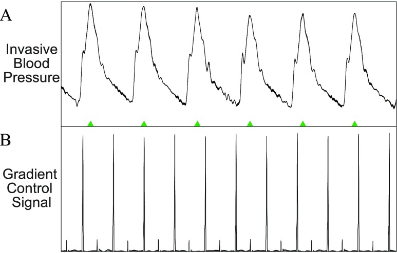
In all pediatric cases analyzed, IBP signals were collected and used clinically. There was no noise detected on the IBP signals during any of the cases, therefore we did not perform analysis on these signals. Figure 8 shows a typical IBP signal waveform during image scanning.
FIGURE 8.
A: Example of invasive blood pressure (IBP) signal during a real-time MRI scan. B: The gradients control signal which reflects the strength and slew rate of gradient waveforms shows no effect on the IBP waveform. Therefore, no adaptive filtering is performed on the IBP signal.
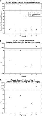
In all but one case (Case #3), PRiME processing with adaptive filtering corrected the trigger detection (Figure 9A). The detected number of triggers using the filtered ECG closely matches the number triggers from the IBP signal, which does not suffer from EMI. This is critical as invasive measures may not always be available, and thus PRiME should enable more successful cardiac MRI scans through improvement in trigger detection after adaptive filtering.
FIGURE 9.
A: Comparison of triggers detected before and after adaptive filtering. The number of triggers detected in the 10 second period decreases from a median of 18 errors to 0 errors, indicating the removal of noise-generated triggers. For this data, the IBP signal which is uncorrupted by EMI was used as a gold standard. B: Percentage change in detected noise peaks due to adaptive filtering. C: Percentage change in mean height of detected noise peaks.
When the PRiME adaptive filter is effective, there is a reduction in the number of noise peaks ranging from 3% to 32% (Figure 9B). The maximum amplitude of the detected noise peaks is reduced by greater amounts, ranging from 27% to 81%, while the mean amplitude is reduced by 39% to 88% (Figure 9C). The number of QRS detection errors was reduced from a median of 18 errors to 0 errors (Figure 9A), with a single false trigger detected on Case #5, and significant errors on Case #3 (where the adaptive filter failed completely). These combined results indicate that even though the adaptive filter does not completely eliminate the noise peaks, the filter is generally very effective in reducing the peaks to manageable levels. For example, the second and fourth cases in Figure 7 demonstrate data successfully filtered, even though the number of detected peaks in both cases was reduced by only 3%.
D. Non-Real-Time Imaging
While the focus of this paper is on the real-time bSSFP sequences used during the catheterization procedure, the PRiME system can be used during other sequences. In Figure 10, a subset of non-real-time scans that are typical of a diagnostic scan are shown, each demonstrating various types of ECG signal noise. Though other scans were also carried out, they were not included in this discussion as they displayed similar noise patterns or had only minor EMI.
Other scans typically performed (e.g., lung perfusion scans) are not shown as very little noise is present on the ECG signals. The anatomical localizer scan (Figure 10 A, 3 orthogonal planes, 30 slices in each orientation acquired with bSSFP, flip angle = 58°, TE/TR = 1.23/2.8 ms, FOV = 400 mm, slice thickness = 4.5 mm, in-plane resolution  mm, parallel imaging acceleration factor = 4, bandwidth = 1157 Hz/pixel) shows considerable noise. The majority of EMI is removed by the filter, but on a longer time scale than shown in the figure, indicating that the filter parameters that are typical for real-time imaging may not be ideal for all MRI scans. However, since localizer scans are short in duration and rarely cardiac gated, the filter settings are less critical.
The pulmonary transit time measurement scan (spoiled gradient echo sequence, sagittal slice, flip angle = 30°, TE/TR = 1.32/34.47 ms, FOV  mm, slab thickness = 20 mm, in-plane resolution
  mm, bandwidth = 400Hz/pixel, 130 consecutive measurements) shows low amplitude, high frequency noise which is effectively removed (Figure 10B). The 3-chamber cardiac cine scan (bSSFP, free-breathing with scan duration = 8–16 s, [24]) shows a small spike at the start of the scan, that is removed by the PRiME adaptive filter (Figure 10C). This low amplitude, short duration noise spike is common among other scans during the start and end of the scan, and is most likely due to large spoiler gradients or coil sensitivity maps. The adaptive filter is usually not effective at removing this type of noise due to its very brief duration.
Finally, the aortic flow scan (free-breathing retrospectively triggered phase contrast spoiled gradient echo sequence, flip angle = 20°, TE/TR = 2.77/5 ms, FOV = 350 mm, in-plane resolution  mm, slice thickness = 6mm, 3 averages, bandwidth = 454Hz/pixel) demonstrates removal of a strong distortion of signal due to respiratory motion (Figure 10D), which can have a large effect on simple triggering methods. Generally, scans which use slowly changing gradients will have little induced noise whereas scans with very short, large amplitude (e.g., step changes producing high frequency components) gradient shapes will induce more noise spikes. In addition, if the duration of an imaging scan is very short, the adaptive filter will not have time to adapt to the gradient signals, reducing its effectiveness.
IV. Conclusion
The primary aim of this work was to develop a MRI compatible high fidelity hemodynamic recording system front-end which could be used during interventional cardiovascular MRI procedures. We designed a compact front-end system, comprised primarily of off-the-shelf components facilitating reproduction by other sites. The PRiME system acquires six ECG electrode signals and two invasive blood pressure signals, and serves as a front-end to a commercial hemodynamic recording system to retain the interface and features typically used during X-ray guided procedures. The schematics and assembly instructions are publicly available [10] without charge, or license. The PRiME system should be considered an investigational device, and the appropriate institutional review and ethics boards should be consulted before use.
Typically, the adaptive filter is capable of significant reductions in MRI gradient-induced noise spikes, which improves interpretation of the ECG signal and MRI triggering capabilities. It is important to note that the analysis of this paper does not consider noise reductions achieved by the overall circuit design and implementation, which could not be easily measured due to the lack of a physiological recording system front-end alternative. The PRiME system is not guaranteed to eliminate all gradient-induce noise in the ECG signals, and there is currently no reliable predictor for when PRiME will be ineffective.
In the research environment in which PRiME was developed, dedicated staff were consistently present to make system adjustments (e.g., adjusting the adaptive filter beta parameter) to improve performance and record data for later troubleshooting. As the PRiME system became sufficiently stable for use in investigational cases, more focus has been placed on increasing usability and the need for manual adjustments. Some areas of active development include the ability to prevent the adaptive filter from entering an unstable state, the ability to automatically reset the filter weights, and the ability to pre-load filter weights based on the active scan to reduce convergence time. We also continue to develop more advanced triggering methods and features for improved performance and flexibility over a larger variety of scans, as well as to minimize manual adjustments by the staff. We are also investigating the use of wireless communication to eliminate the need for the fiber optic cable. Finally, we will continue to evaluate and improve the designs of the front-end electronics and adaptive filter algorithm.
We have successfully designed and implemented an MRI compatible high fidelity hemodynamic recording front-end system for use in interventional cardiovascular MRI procedures. The system performance has been adequate to be used routinely in over 39 pediatric [3] and 102 adult [4] cardiovascular interventional procedures as an investigational device. We have demonstrated significant reductions in MRI-induced noise on ECG signals. The PRiME open-source design and fabrication guidance enables duplication by other researchers in the interventional cardiovascular field, allowing further improvements and research opportunities.
Acknowledgement
A. Z. Faranesh was with the National Institutes of Health, Bethesda, MD 20892 USA.
Funding Statement
This work was supported in part by the Intramural Research Program of the NIH Center for Information Technology and the Division of Intramural Research of the National Heart, Lung, and Blood Institute, NIH under Grant Z01-HL006040.
References
- [1].Ratnayaka K., Faranesh A. Z., Guttman M. A., Kocaturk O., Saikus C. E., and Lederman R. J., “Interventional cardiovascular magnetic resonance: Still tantalizing,” J. Cardiovascular Magn. Reson., vol. 10, no. 1, p. 62, Dec. 2008. [DOI] [PMC free article] [PubMed] [Google Scholar]
- [2].Wu V.et al. , “Adaptive noise cancellation to suppress electrocardiography artifacts during real-time interventional MRI,” J. Magn. Reson. Imag., vol. 33, no. 5, pp. 1184–1193, May 2011. [DOI] [PMC free article] [PubMed] [Google Scholar]
- [3].Ratnayaka K.et al. , “Radiation-free CMR diagnostic heart catheterization in children,” J. Cardiovascular Magn. Reson., vol. 19, no. 1, p. 65, Sep. 2017. [DOI] [PMC free article] [PubMed] [Google Scholar]
- [4].Rogers T.et al. , “CMR fluoroscopy right heart catheterization for cardiac output and pulmonary vascular resistance: Results in 102 patients,” J. Cardiovascular Magn. Reson., vol. 19, no. 1, p. 54, Jul. 2017. [DOI] [PMC free article] [PubMed] [Google Scholar]
- [5].Faranesh A. Z., Hansen M., Rogers T., and Lederman R. J., “Interactive black blood preparation for interventional cardiovascular MRI,” J. Cardiovascular Magn. Reson., vol. 16, no. 1, p. P32, 2014. [Google Scholar]
- [6].Dimick R., Hedlund L., Herfkens R., Fram E., and Utz J., “Optimizing electrocardiograph electrode placement for cardiac-gated magnetic resonance imaging,” Invest. Radiol., vol. 22, no. 1, pp. 17–22, Jan. 1987. [DOI] [PubMed] [Google Scholar]
- [7].Tse Z.et al. , “1.5 tesla MRI-conditional 12-lead ECG for MR imaging and intra-MR intervention,” Magn. Reson. Med., vol. 71, no. 3, pp. 1336–1347, Mar. 2014. [DOI] [PMC free article] [PubMed] [Google Scholar]
- [8].Nijm G. M., Swiryn S., Larson A. C., and Sahakian A. V., “Extraction of the magnetohydrodynamic blood flow potential from the surface electrocardiogram in magnetic resonance imaging,” Med. Biol. Eng. Comput., vol. 46, no. 7, pp. 729–733, Jul. 2008. [DOI] [PubMed] [Google Scholar]
- [9].Gregory T. S., Oshinski J., Schmidt E. J., Kwong R., Stevenson W., and Tse Z. T. H., “Continuous rapid quantification of stroke volume using magnetohydrodynamic voltages in 3T magnetic resonance imaging,” Circulat., Cardiovascular Imag., vol. 8, no. 12, p. e003282, Dec. 2015. [DOI] [PMC free article] [PubMed] [Google Scholar]
- [10].Kakareka J. W. (2017). NHLBI-MR/PRiME. [Online]. Available: https://github.com/NHLBI-MR/PRiME [Google Scholar]
- [11].Kakareka J. W. Custom IBP Cables. Accessed: 2017. [Online]. Available: https://github.com/NHLBI-MR/PRiME/blob/master/Gen1/Assembly/Custom_IBP_Cables.pdf [Google Scholar]
- [12].Kakareka J. W. (2017). Circuits—PSA. National Institutes of Health Accessed: 2017. [Online]. Available: https://github.com/NHLBI-MR/PRiME/tree/master/Gen1/Components/PSA/Circuits [Google Scholar]
- [13].Low Cost Low Power Instrumentation Amplifier AD620, Analog Devices, Norwood, MA, USA, 2011. [Google Scholar]
- [14].Kakareka J. W. CSaAF. Accessed: 2017. [Online]. Available: https://github.com/NHLBI-MR/PRiME/tree/master/Gen1/Components/CSaAF [Google Scholar]
- [15].Widrow B., McCool J. M., Larimore M. G., and Johnson C. R., “Stationary and nonstationary learning characteristics of the LMS adaptive filter,” Proc. IEEE, vol. 64, no. 8, pp. 1151–1162, Aug. 1976. [Google Scholar]
- [16].Kakareka J. W. PSC. Accessed: 2017. [Online]. Available: https://github.com/NHLBI-MR/PRiME/tree/master/Gen1/Components/PSC [Google Scholar]
- [17].Xiao B., Kakareka J. W., Pursley R. H., Pohida T., Lederman R. J., and Faranesh A., “MRI compatible hemodynamic recording system,” J. Cardiovascular Magn. Reson., vol. 15, no. 1, p. P22, Jan. 2013. [Google Scholar]
- [18].Felblinger J., Lehmann C., and Boesch C., “Electrocardiogram acquisition during MR examinations for patient monitoring and sequence triggering,” Magn. Reson. Med., vol. 32, no. 4, pp. 523–529, Oct. 1994. [DOI] [PubMed] [Google Scholar]
- [19].Saikus C. E. and Lederman R. J., “Interventional cardiovascular magnetic resonance imaging: A new opportunity for image-guided interventions,” JACC Cardiovascular Imag., vol. 2, no. 11, pp. 1321–1331, Nov. 2009. [DOI] [PMC free article] [PubMed] [Google Scholar]
- [20].Modan B., Keinan L., Blumstein T., and Sadetzki S., “Cancer following cardiac catheterization in childhood,” Int. J. Epidemiol., vol. 29, no. 3, pp. 424–428, Jun. 2000. [PubMed] [Google Scholar]
- [21].Kleinerman R. A., “Cancer risks following diagnostic and therapeutic radiation exposure in children,” Pediatric Radiol., vol. 36, no. 2, pp. 121–125, Sep. 2006. [DOI] [PMC free article] [PubMed] [Google Scholar]
- [22].Dorfman A. L.et al. , “Use of medical imaging procedures with ionizing radiation in children: A population-based study,” Arch. Pediatric Adolesc. Med., vol. 165, no. 5, pp. 458–464, May 2011. [DOI] [PMC free article] [PubMed] [Google Scholar]
- [23].Johnson J. N.et al. , “Cumulative radiation exposure and cancer risk estimation in children with heart disease,” Circulation, vol. 130, no. 2, pp. 161–167, Jul. 2014. [DOI] [PMC free article] [PubMed] [Google Scholar]
- [24].Xue H., Kellman P., LaRocca G., Arai A. E., and Hansen M. S., “High spatial and temporal resolution retrospective cine cardiovascular magnetic resonance from shortened free breathing real-time acquisitions,” J. Cardiovascular Magn. Reson., vol. 15, no. 1, p. 102, Nov. 2013. [DOI] [PMC free article] [PubMed] [Google Scholar]


