

Abstract
Crystallization of membrane proteins is a critical step for uncovering atomic resolution 3-D structures and elucidating the structure-function relationship. Microseeding, the process of transferring sub-microscopic crystal nuclei from initial screens into new crystallization experiments, is an effective, yet underutilized approach to grow crystals suitable for X-ray crystallography. Here, we report simplified methods for crystallization of membrane proteins that utilize microseeding in X ray transparent microfluidic chips. First, a microfluidic method for introduction of microseed dilutions into metastable crystallization experiments is demonstrated for photoactive yellow protein and cytochrome bo3 oxidase. As microseed concentration decreased, the number of crystals decreased while the average size increased. Second, we demonstarte a microfluidic chip for microseed screening, where many crystallization conditions were formulated on-chip prior to mixing with microseeds. Crystallization composition, crystal size, and diffraction data were collected and mapped on phase diagrams, which revelaed that crystals of similar diffraction quality and size typically grow in distinct regions of the phase diagram.
Table of Contents
Microfluidic platforms for formulation of crystallization trials with microseeds to enable the growth of high-quality protein crystals
Introduction
Membrane proteins are of critical importance for cellular function, with roles ranging from transportation to enzymatic catalysis. Elucidation of functional mechanisms requires atomic resolution structures which are typically solved via X ray crystallography. The process of consistently growing diffraction quality protein crystals is one of the most significant obstacles to obtaining protein structures. Random screening procedures are implemented because the prediction of crystallization conditions a priori is unreliable,1 and further, reports have shown that oftentimes crystallization results vary in separate experiments with identical formulations.2 The expected reason for these difficulties in crystallization is the stochastic nature of nucleation, which is unavoidable even in carefully controlled experiments (e.g., controlled temperature, humidity, purity).2–5
The formation of protein crystals can be conceptualized in terms of phase diagrams that map the solubility and aggregation properties of a protein in a precipitant solution.6 Supersaturation drives the nucleation and growth of protein crystals in solution. Two distinct supersaturation regimes impact how crystals form and grow: (1) the labile regime, where stable crystal nuclei spontaneously form and ripen, and (2) the metastable regime, where the formation of new nuclei is unfavored, but pre-formed nuclei can ripen. A typical crystallization trial is formulated in the labile regime and produces tens to hundreds of new nuclei through spontaneous, uncontrolled nucleation. Structure determination by X-ray crystallography requires either a few large crystals for traditional crystallography, or many small crystals of homogeneous size for serial femtosecond crystallography,7,8 both of which are difficult to grow reliably under conditions of uncontrolled nucleation. Consistent growth of large crystals can be achieved through careful inspection of phase diagrams and through techniques such as microseeding to separate nucleation and growth.9
During initial crystallization screens, any resulting microcrystals, irregular crystals, or other crystalline material (Fig. 1), while typically not useful for X-ray diffraction, can be collected and crushed to form a solution of sub-microscopic crystal nuclei.9,10 Microseeding, the process of introducing such nuclei into a crystallization mixture, is tool for reliably growing large, diffraction-ready protein crystals.11–16 The process of microseeding decouples the two steps in crystal formation – nucleation and growth – by supplying a finite number of nuclei into a metastable protein-precipitant mixture. When microseeds are introduced into a metastable mixture, no self-nucleation events occur in the crystallization trials and only the supplied nuclei are expected to grow into crystals.
Fig. 1.

Crystals unsuitable for single crystal X-ray crystallography grown without microseeds. (a) Photoactive yellow protein (PYP) nucleates uncontrollably and grows in clusters of hundreds of crystals. (b) Cytochrome bo3 oxidase (cyt bo3) grows in uncontrolled showers of tiny crystals without microseeds.
The usage of microseeds also extends to routine screening experiments in a method known as microseed matrix screening. When screening for crystallization of a new protein target with an unknown crystallization phase diagram, the addition of microseeds can enhance screening success rates.17–20 Microcrystals from initial screens are crushed to form microseeds, and then used during future screening experiments. The best conditions from the subsequent screens are harvested and the process is iterated to produce diffraction-quality crystals. When screening with microseeds, the phase space for successful crystallization broadens, resulting in an increased number of hits from both metastable and labile compositions. Microseed matrix screening has been used successfully for proteins that readily precipitate,14 for proteins with substrates that hydrolyze during slow crystal growth,21 for antibody-antigen complexes,11 and for many more cases.22–25
Traditionally, microseeding is performed by first mixing protein and precipitant solutions in a sealed crystallization well plate.9 The protein-precipitant mixture reaches equilibrium, and then a small volume of microseed solution is carefully added to the droplet. The addition of microseeds is an invasive procedure that necessitates de-sealing the crystallization well, which shifts the equilibrium of the droplet and the vapor phase surrounding it. Many efforts to simplify and automate microseeding have been successfully implemented for various proteins.18,19,26,27 Microseeding robots pre-mix the protein, precipitant and microseed solution during crystallization set up.18 Femtosecond laser ablation has been used to eject crystal fragments that serve as seed in the same crystallization drop.28 Acoustic matrix microseeding utilizes acoustic waves to deliver nanoliter volumes of seed suspension into protein drops.29 Despite these technologies and the promise of improved crystallization success with microseeding, it remains an under-utilized tool and is often chosen as the last resort when other attempts to grow high quality crystals have failed. While the procedure for making microseed stock solutions is simple, the process of introducing microseeds to the crystallization droplet requires manual skill and experience. Further, no method provides a reliable non-invasive way for introducing microseeds after a crystallization trial reaches metastable equilibrium.
Many microfluidic platforms have been developed to simplify complex and repetitive crystallization tasks. These include high-throughput crystallization platforms that formulate trials by free interface diffusion in microwells30 or in droplets,31 and by dialysis in microwells.32 Additionally, platforms have been developed for applications that require sequential mixing of multiple components (>2).33–35 Further, to mitigate difficulties associated with crystal harvesting,36 efforts have produced microfluidic platforms built from materials that are compatible with in situ X-ray analysis.37–40 Two microfluidic platforms have demonstrated seeding for the purpose of optimizing crystal growth: a method for seeding crystals of soluble proteins in droplets41 and an X-ray transparent platform for microseeding active pharmaceutical ingredients.42
Here, we report two X-ray transparent microfluidic platforms to simplify microseeding-based membrane protein crystallization techniques. First, a previously designed microfluidic crystallization chip38 was re-purposed for mixing microseeds into crystallization trials. Metastable mixtures formulated off-chip were filled into one set of half-wells, and microseed dilutions were filled into adjacent half-wells. The actuation of a normally-closed valve triggered crystallization with microseeds by free-interface diffusion. This platform was used to observe crystal growth as a function of microseed dilution for a model protein and a membrane protein. In the second approach, a new microfluidic chip was developed for microseed screening where metastable mixtures were formulated and incubated on-chip prior to the introduction of microseeds. This approach enables the screening of many different metastable compositions to discover or optimize crystallization conditions with microseeds. For validation, these microfluidic platforms were applied to the microseeded crystallization of photoactive yellow protein (PYP, soluble protein), and cytochrome bo3 oxidase (cyt bo3, membrane protein). The effectiveness of microseeding on-chip was analyzed by observing growth trends with microscopy and measuring diffraction quality in situ with X rays. We demonstrate the successful growth of crystals where size depends on the amount of microseeds provided. Further, we extend this approach to screening with microseeds and observe that crystals of certain habits and diffraction quality grow preferentially in distinct regions of the phase diagram.
Materials and methods
Preparation of protein samples
Photoactive yellow protein from Halorhodospira halophila was cloned and expressed in Escherichia coli (strain BN9626) and purified as published previously.43 Briefly, polyhistidine-tagged apoPYP heterologously over-expressed in E. coli was reconstituted in vitro with the anhydrous derivative of the chromophore p-coumaric acid and the polyhistidine-tag was cleaved by incubating it with enterokinase.
Cytochrome bo3 oxidase (cyt bo3) from Escherichia coli (strain C43(DE3)) was purified as published previously.44 Briefly, polyhistidine-tagged cyt bo3 was overexpressed by IPTG induction in E. coli and solubilized in dodecylmaltoside. Prior to crystallization, the sample was treated with 1 mM potassium ferricyanide to fully oxidize the protein and exchanged into 20 mM Tris-HCl, pH 8 with 0.7% beta-octylglucoside.
Fabrication of photoresist-on-silicon masters for replica molding
Photoresist-on-silicon masters were created by photolithography with transparency photomasks (Fig. S1) with SU8-2050 photoresist45 (Microchem) for patterns with 50–100 µm-tall vertical features. All photoresist-on-silicon masters were treated with (tridecafluoro-1,1,2,2-tetrahydrooctyl) trichlorosilane (Gelest) in a vacuum chamber for 4 h for easy release of soft lithographic replicas.46
Fabrication of thin PDMS/COC microfluidic devices
Polydimethylsiloxane (PDMS) layers were fabricated using standard replica molding procedures46,47 by spin-coating a layer of PDMS onto photoresist-on-silicon masters with total height ~10 µm thicker than the corresponding photoresist feature height (Fig. S2). For the fluid layer, PDMS was mixed with monomer:cross-linker ratio of 15:1 and cured at 90 °C for 7–9 min. For the control layer, PDMS was mixed with monomer:cross-linker ratio of 5:1 and cured at 90 °C for 3 min. The chips were assembled as follows: (i) a flat cyclic olefin copolymer (COC) sheet was irreversibly bonded to the PDMS control layer, and (ii) the resulting COC-PDMS control layer assembly was irreversibly bonded to the PDMS fluid layer. Permanent COC-PDMS bonding in step (i) was achieved by activating the surfaces using plasma treatment48 in a plasma cleaner (Harrick, Model PDC-001) for 1 min at 500–700 mTorr. The irreversible PDMS-PDMS bond in step (ii) was created via the standard multilayer soft lithography approach47 by placing layers of PDMS with different monomer:cross-linker ratios in conformal contact and heating them at 70°C for 2 h. Inlet holes for the control and the fluid layer were drilled in the COC-PDMS-PDMS assembly using a 300 or 750 µm drill bit (McMaster-Carr). The COC-PDMS-PDMS assembly was then placed on an unpatterned COC substrate and a reversible bond between the PDMS fluid layer and the COC substrate formed spontaneously.
Crystallization in well plates and microseed preparation
Vapor diffusion in hanging drops was set up as previously reported.49,50 Un-seeded crystallization in well plates yielded clusters of crystals after 7–10 days of incubation for PYP, and microcrystalline showers for cyt bo3 (Fig. 1). These crystals, while unsuitable for X-ray analysis because of difficulties in isolating individual crystals from the clusters or microcrystalline showers, were used to create microseed solutions. Crystals from 2–3 crystallization wells each for PYP and cyt bo3 were harvested from hanging drops and transferred into 500 µL of a concentrated precipitant solution (PYP: 3M ammonium sulfate, cyt bo3: 13% PEG 1500), and then transferred to a tissue grinder (Kontes Duall model K885460-0021, Thermo Fisher Scientific) where they were crushed by inserting and rotating the pestle by hand for 2 minutes on ice to make the stock microseed solution. After crushing, dynamic light scattering (Malvern Zetasizer) was used to measure microseed size (PYP: 300 nm, cyt bo3: 140 nm). Various concentrations of the microseed solutions were prepared by serially diluting the stock solution in concentrated precipitant solutions at ratios of 1:1, 1:2, 1:4, 1:10, 1:20, and 1:50. Repeating the same crystallization experiments at reduced concentrations in well plates with microseeds successfully yielded crystallization after 2 days. Microseed stocks and dilutions were either used immediately or flash frozen in liquid nitrogen and stored at −80°C until use.
Computational fluid dynamic simulations of mixing time
Diffusive mixing of protein in microfluidic compartments was simulated using a 2D finite element solver, COMSOL Multiphysics (COMSOL). The lateral dimensions of six different sets of protein and precipitant compartments in this model are identical to those in the actual chip (Fig. S3). A ‘No Flux’ boundary condition was applied to external walls and non-mixing interfaces. When mixing, the valves rise and leave an open liquid-liquid interface for free interface diffusion. The model simulated 60 minutes of mixing at 1 minute intervals. The mesh was “finer”, with a total of 1319 elements. The initial concentrations of cyt bo3 oxidase were 10–50 mg/mL, and the diffusion coefficient was 4 × 10⁻⁷ cm2/s.51 The initial concentration of PEG 1500 was 0.07 mM, and the diffusion coefficient was 3 × 10⁻⁶ cm2/s.52 The solutions were assumed to be dilute and that the diffusion coefficients were independent of concentration. For each half-well, the average concentration was determined using a surface integral scaled to the height of the actual microfluidic well (50 µm).
Synchrotron X-ray data collection and analysis
In situ X-ray diffraction data were collected at APS (Advanced Photon Source) synchrotron, Argonne National Laboratory at beamline 23-ID-B GM/CA (General Medical Sciences and Cancer Institutes’ Structural Biology Facility). Data were collected from all cyt bo3 crystals that produced diffraction in 0.2–0.4° steps with 0.2–0.4 s exposures and a sample-to-detector distance between 500–600 mm with a Pilatus 6M detector. All data were collected at room temperature. Each crystal was subjected to 5–10 exposures to limit deterioration of diffraction quality and resolution due to radiation. During diffraction experiments, each crystal in each well was numbered and recorded to match diffraction data to its corresponding protein-precipitant composition and size.
Image analysis of cytochrome bo3 oxidase crystals
Images of cyt bo3 crystals were captured using an upright stereo microscope (Leica MDG33) equipped with a macro lens and a digital camera (Leica DFC295). Images were analyzed manually using ImageJ. The length and width of up to 30 crystals in each well were recorded and correlated to the protein-precipitant condition used for crystal growth (Fig S4).
Results and discussion
As a starting point, microfluidic chips were fabricated based on designs detailed in the work of Guha et al.38 These multilayered microfluidic chips were designed for high X-ray transmission (>75% X-ray transmittance at λ = 1Å), and were re-purposed in this work to facilitate the addition of microseed solutions to crystallization experiments. Sets of integrated microvalves controlled the metering and mixing of crystallization solutions. Devices were comprised layers of polydimethylsiloxane (PDMS), a flexible polymer that enables the functionality of valves, sandwiched between thin layers of cyclic olefin copolymer (COC), a rigid polymer that acts as an impermeable barrier to air and water (Fig. 2a). At a total thickness of ~200 µm, these chips have been demonstrated to be effective all-in-one tools for crystal growth and in situ serial X-ray data collection at room temperature.38
Fig. 2.

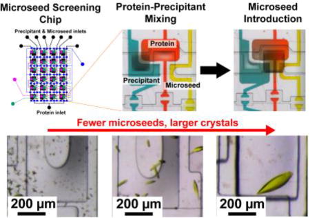
A microfluidic approach for introducing microseeds to crystallization experiments. (a) Exploded view of a single crystallization well comprised of four layers: an impermeable cyclic olefin copolymer top layer bonded to an elastomeric polydimethylsiloxane control layer containing valves, a PDMS fluid layer to contain protein, precipitant and seed solutions, and a COC bottom layer. (b) Schematic of a 24-well array chip used for microseeding. Fluid layer is shown in blue, and the valve lines, V1, V2 and V3, are colored based on their function (see legend). The window structures (yellow) decrease the total material in the path of the X-ray beam. For microseeding experiments, different microseed dilutions were loaded (inlets 2–7) and a pre-mixed protein-precipitant solution (inlet 1) prior to on-chip mixing. (c,d) Results from screening several microseed dilutions – at greater seed dilutions (lower seed concentration), PYP crystals (c) grew into fewer, larger crystals and cyt bo3 crystals (d) grew into fewer, thicker crystals.
Two types of microfluidic platforms were built for microseeding experiments: (A) a platform for microseed introduction to pre-mixed metastable mixtures, and (B) a platform for on-chip generation of metastable mixtures and subsequent microseed screening.
A. Microfluidic platform for microseeded crystallization
The device for simplifying crystallization with microseeds operates using the same principles described in previous work.38 Briefly, ~3 µL of a pre-formulated protein-precipitant mixture was placed onto port 1 and introduced to the protein-precipitant half-wells by dead-end filling (Fig. 2b), a vacuum-actuated process that displaces air in each compartment with the protein-precipitant mixture. 1 µL of a microseed solution was placed onto each microseed inlet (ports 2–7), and they were introduced to microseed half-wells by dead-end filling. A normally-closed valve separating each set of two half-wells was then opened for 5 minutes to allow mixing of microseeds and the protein-precipitant mixture by free interface diffusion. The amount of microseeds transferred to the crystallization droplet depended on (a) the length of mixing time, and (b) the dilution of the microseed stock. Here, the mixing time was held constant while the microseed dilution was varied.
The effect of microseeds on crystallization was tested for two proteins: (1) photoactive yellow protein (PYP), a protein that grows into well-ordered crystals only in the presence of microseeds, and (2) cytochrome bo3 oxidase (cyt bo3), a fragile membrane protein with a known crystallization condition that has previously produced some crystals and an incomplete, low resolution structure. Microseeding experiments on-chip were performed by first preparing metastable mixtures of protein and precipitant (1:1 volume ratio) in an Eppendorf tube (20 mg/mL PYP with 2.6 M ammonium sulfate; 15 mg/mL cyt bo3 with 10% w/v PEG 1500, 100 mM HEPES pH 7.0, 100 mM NaCl, 100 mM MgCl2, and 5% ethanol). Each metastable solution was equilibrated for 1 hour on ice. Each mixture was then introduced to a microfluidic chip through port 1. Serial dilutions of microseed solution were introduced through ports 2 through 7 to fill the half-wells adjacent to the protein-precipitant mixtures (Fig. 2b). The metastable protein-precipitant mixture and microseed wells mixed by free-interface diffusion for 5 minutes by opening the microvalve that separated the wells. Experiments without microseeds resulted in no crystal growth, verifying that the mixtures were metastable rather than labile.
A range of microseed dilutions were tested, from 1:1 (high concentration) to 1:50 (low concentration). In the presence of microseeds, crystals first appeared after 1 day (compared to 7 days without microseeds) and reached full size after 4 days (PYP) or 7 days (cyt bo3). For both proteins, high concentrations of microseed resulted in many small or needle-like crystals. As microseed concentration decreased, fewer, larger crystals grew (Fig. 2c,d). These observations agree with expected trends for crystal growth in a metastable crystallization environment where protein molecules in solution attach to existing crystals rather than form new nuclei.53 This also prevented “gross twinning” of PYP crystals reported previously.54 A 1:20 microseed dilution yielded large, isolated crystals of PYP, while a 1:50 ratio yielded the thick, individual crystals of cyt bo3. The disparity in these optimal dilution ratios has two origins: first, depending on the protein and its solubility, some microseeds may dissolve during the mixing of the metastable mixture with microseeds. Second, an imprecise number of crystals were used to generate microseed stock solutions, so the true microseed concentration varies from seed stock to seed stock. This will be the case for most laboratories, and the optimal dilution ratio must be determined experimentally. Once an optimal microseed dilution was determined, large crystals could be grown by repeating crystallization with the same seed stock.
X-ray diffraction data were collected for PYP and cyt bo3 crystals on-chip. The entire microfluidic chip was placed on a magnetic cap mount and secured with a set screw before being attached to the goniometer. Due to the chip’s construction from X-ray transparent polymers and low thickness (<200 µm), crystals were targeted and analyzed at room temperature using the on-axis microscope available at the beamline. PYP crystals diffracted to a maximum resolution of 1.19 Å, and a complete dataset was combined from several crystals to 1.32 Å (Table S1). The diffraction data set had high quality diffraction spots and good signal-to-noise, characteristic of good data collected from this on-chip approach and comparable to other crystallographic studies of PYP. Approximately 20 crystals from the membrane protein, cyt bo3, were tested, but they diffracted poorly, with sparse spots up to ~12 Å. While on-chip microseeding aided the growth of large cyt bo3 crystals, X-ray diffraction revealed that the quality of the crystals was poor. In the case of cyt bo3, large crystal size was not an indicator of good diffraction quality. In summary, a microfluidic chip was successfully used to demonstrate microseeding and the dilution of microseed was optimized for the growth of large crystals for PYP and cyt bo3.
B. Microfluidic platform for microseed screening
Timing of microseed introduction is an important consideration for microseed screening experiments. If the microseeds are introduced too early, they may dissolve. Consider the common approaches for introducing microseeds: (1) introducing microseeds into the protein solution or precipitant solution, which results in partial or complete dissolution of microseeds in unsaturated solutions, (2) introducing microseeds into the protein-precipitant mixture immediately after mixing, which faces similar potential problems of microseed dissolution, or (3) introducing microseeds at some time after equilibration, which requires manual de-sealing of the crystallization well, an invasive method which disrupts the equilibrium between the crystallization drop and the vapor phase around it. Seed and crystal dissolution have been explored from both theoretical6,9,19 and experimental perspectives.18,26,55,56 Experimenters have devised techniques to prevent seed dissolution, such as microseeding crystallization in capillaries56 and using dynamic light scattering to generate microseeds in situ prior to diluting the droplet into metastability.55 Another method proposed that microseeds were stable enough to not dissolve across a variety of crystallization conditions.18 A follow-up study indicated that the increase in crystal induction time was largely due to a chemical shift of conditions toward the microseed mother liquor, and the microseeds had probably dissolved.26 These studies reinforce a main requirement for microseeding: microseeds should be introduced into a pre-equilibrated crystallization mixture. The microfluidic platform presented here (B) overcomes limitations in the prior methods for microseed screening, offering a new mixing strategy for introducing microseeds into many different pre-equilibrated mixtures of protein and precipitant without dissolving microseeds or significantly disturbing the metastable crystallization droplet.
In the interest of introducing microseeds simultaneously into a diverse set of crystallization conditions for crystal optimization, a 24-well microseed screening array was developed. This type of technique can be used to improve and optimize the diffraction quality of poorly diffracting crystals such as those of cyt bo3. This new approach for the formulation of microseed crystallization trials uses two separate free-interface diffusion mixing steps: (1) protein and precipitant compartment mixing, waiting for equilibration, followed by (2) protein, precipitant and microseed compartment mixing (Fig. 3). Compared to the earlier microfluidic approach (Fig. 2) where a single crystallization composition was generated by pre-equilibrating protein and precipitant off-chip, this chip generates an array of protein-to-precipitant ratios on-chip for grid or random matrix screening of precipitants with microseeds. The key features of this platform are the arrangement of microfluidic wells which facilitate filling and mixing, and subsequent mixing of microseed any time after protein-precipitant mixing (Fig. 3c).
Fig. 3.

A three-component microfluidic array chip for microseed screening. (a) Schematic of a 24-well three-component array chip used for microseeding, with fluid lines in black, and the various valve lines, V1, V2, and V3, colored based on their function (see legend). (b) Exploded view of a single well, showing device construction with a total material thickness of ~200 µm. (c) Top view of the aligned fluid layer and control layer, showing relative positions of protein, precipitant, and microseed compartments and the two separate mixing valves.
Three sets of normally closed microvalves control filling and mixing. First, protein, precipitant, and microseed were simultaneously introduced into separate microfluidic compartments by dead-end filling initiated by vacuum actuation of V1 (Fig 3a, 4b-i). Next, protein and precipitant mixed by free-interface diffusion by vacuum actuation of V2 for 30 minutes (Fig. 3a, 4b-ii). V2 was then closed and the protein and precipitant wells incubated for 1 hour to reach a metastable composition. Finally, vacuum actuation of V3 for 5 minutes introduced microseeds to the metastable protein-precipitant mixtures (Fig. 3a, 4b-iii). This 5 minute valve actuation introduced a repeatable amount of seeds (controlled by concentration and mixing time) to each half-well. Further, microseed introduction did not significantly dilute the mixture or disrupt the equilibrium due to the relatively small volume of microseed solution. The chips were then sealed and incubated at 4°C or 20°C, and monitored daily for crystallization.
Fig. 4.

Sequence for mixing and filling steps for microseeding in three-component array chip. (a) Schematic of array chip showing inset of a single crystallization well – three sets of mixing valves are indicated on the inset, (1), (2), and (3). (b) Schematics (1 – before filling or mixing; 2 – after filling or mixing) and optical micrographs (right) of step. Arrows indicate free interface diffusion interfaces (b-i) Protein, precipitant, and microseed are placed on their respective inlets, and actuation of valve line 1 initiates dead-end filling. (b-ii) Valve line 2 is actuated for 30 minutes to mix protein and precipitant. (b-iii) After 1 hour of incubation, metastable protein-precipitant mixtures have formed (light and dark purple). Valve line 2 is then actuated for 5 minutes to introduce microseeds to each metastable mixture.
Mixing time and the final concentrations of protein and precipitant were determined through computational fluid dynamics simulations. The diffusion coefficient for cyt bo3 in water was estimated based on another large protein (catalase: 247 kDa, 4.1 × 10⁻⁷ cm2/s). A reported value for the diffusion coefficient of the precipitant, polyethylene glycol, in water was determined from previous reports (3.2 × 10⁻⁶ cm2/s).52 Simulation geometries were based on the real dimensions of the microfluidic chip, and free-interface diffusion was simulated for 60 minutes at 1 minute intervals. Diffusion of protein and precipitant were modeled, although precipitant rapidly mixes to completion on the time-scale of protein mixing. Time-concentration plots were constructed by a surface integral of concentration in the protein well and precipitant well separately (Fig. S3b). Diffusive mixing of protein nears completion after 60 minutes. Mixing for just 30 minutes with the valve open resulted in two different metastable compositions in each half-well. After a post-mixing incubation (60 minutes) with the valve closed, each half-well reached a homogeneous metastable concentration, calculated by the surface integral. These half-well concentrations were used to build crystallization phase diagrams (Fig. 5).
Fig. 5.

Microseed screening results for cytochrome bo3 oxidase. (a) Composition-composition phase diagram showing different regions of average X-ray diffraction resolution for crystals, as indicated by the size and color of each point. Resolutions were measured from a minimum of 5 diffraction frames. (b) Composition-composition diagram showing crystal aspect ratios - needle-like crystals (aspect ratio > 5) grew more often at low precipitant concentrations, while thicker crystals grew (aspect ratio < 5) grew at more at high precipitant concentrations. The solid black estimated solubility curve was drawn by inspection: no crystallization was observed at conditions below the line when tested with microseeds.
Application: Microseed screening of cytochrome bo3 oxidase
The microseed screening platform was applied to the crystallization of the membrane protein cyt bo3 to determine conditions that produced crystals with improved diffraction quality. A grid screen was implemented to screen conditions around the cyt bo3 / PEG 1500 crystallization condition previously used. Cyt bo3 microseeding experiments were performed with a range of initial protein concentrations between 10 mg/mL and 50 mg/mL. Stock precipitant solutions contained initial concentrations between 9% and 12%w/v PEG 1500, while the other components (NaCl, MgCl2, HEPES, ethanol) were held at constant concentrations. The optimal microseed dilution from before (Fig. 2d), 1:50, also produced large, individual crystals in these chips and is used for all experiments discussed herein. Crystallization results were recorded after 7 days and pictures were taken of each crystallization well for image processing. X-ray diffraction experiments were conducted within 14 days of setting up crystallization trials.
Diffraction data and crystal aspect ratios were mapped on protein composition / precipitant composition phase diagram to evaluate the influence of microseed screening on crystal habit and diffraction resolution (Fig. 5). An estimated solubility curve was drawn on the phase diagram by inspection. Crystallization trials were formulated with as little as 1.5% w/v PEG1500 and 3 mg/mL cyt bo3, and the estimated solubility curve indicates the approximate minimal compositions above which crystals grew with microseeds. Diffraction resolutions plotted on the phase diagram (Fig. 5a) show that diffraction quality segregates into distinct regions. At high precipitant concentrations and moderate-to-low protein concentrations, crystal diffracted the best (average: 10.5 Å). At low precipitant concentrations and moderate-to-high protein concentrations, crystals diffracted to much poorer resolutions (average: >13 Å). The higher quality crystals in this work, while not of sufficient quality for structure resolution, were sufficient for data indexing due to strong, albeit low resolution diffraction. By using microseeds to control nucleation, crystals with enhanced diffraction quality could be reliably grown at certain compositions.
A second phase diagram was mapped using data from the same crystals that instead indicates the aspect ratios of each crystal (Fig. 5b). Crystal size and shape also segregates into distinct regions. At moderate-to-low protein concentrations and high precipitant concentrations, crystals formed in short, rectangular or cubic shapes (average AR: 3.5). At moderate-to-high protein concentrations and low precipitant concentrations, crystals formed in long, needle-like shapes (average AR: 6). The needle-like crystals typically diffracted poorly, while the rectangular/cubic crystals yielded higher diffraction resolutions.
While the supersaturation condition ultimately determines the final crystallization results, the timing of microseed addition on-chip allows access to many regions of supersaturation that may have previously been inaccessible due to microseed dissolution. These results demonstrate that under nucleation-controlled conditions, the quality and morphology of membrane protein crystallization can be manipulated by varying supersaturation. Notably, crystallization trials in some supersaturation regions reliably yield crystals with consistent diffraction quality or aspect ratios (Fig. S5). For instance, the population of crystals tested for diffraction at high precipitant concentration and moderate-to-low protein concentration diffracted to 10.5 ± 0.2 Å. The crystals grown at high protein concentration and low precipitant concentration grew as needles with aspect ratios of 6 ± 0.3. The standard errors and variability are small, likely because crystal growth with microseeds bypasses the stochastic nature of nucleation.
Conclusions
In summary, crystallization with microseeds of soluble and membrane proteins was demonstrated with two types of X-ray transparent microfluidic array chips. These approaches separate the fundamental nucleation and growth regimes to favor the formation of large, individual crystals that can be used for X ray crystallography. Microfluidic platforms greatly simplify the execution of microseeding experiments and produce consistent results, reducing the required level of manual expertise while only requiring few peripherals (i.e., a small vacuum pump and a pipette).
In the first microfluidic approach (A), 24-well array chips with wells comprised of two compartments, one for a metastable protein-precipitant mixture and the other for a microseed solution, were used to crystallize photoactive yellow protein (PYP) and cytochrome bo3 oxidase (cyt bo3). Optimal seed dilutions were determined that grew the best crystals for reported crystallization conditions. Microseeded PYP crystals diffracted very strongly to 1.19 Å, however cyt bo3 crystals diffracted poorly to ~12 Å despite their large size, indicating that even with microseeds, the composition of protein and precipitant used here did not support the growth of highly ordered crystals.
In the second microfluidic approach (B), a new 24-well microfluidic array chip for microseed screening was developed. This approach addresses the limitations of off-chip mixing required for the first approach. To set-up grid screens with microseeds, protein, precipitant and microseed are first loaded into separate compartments. In two separate mixing steps, the microfluidic chip first mixes a gradient of metastable protein-precipitant solutions before introducing microseed through a subsequent mixing step. The resulting phase diagrams constructed from these experiments showed that crystal diffraction quality and appearance depend on the composition of protein and precipitant: some compositions favor small aspect ratio crystals with decent diffraction, while others favor large aspect ratio crystals (needles) with poor diffraction. While even the best crystals from this screen were not suitable for solving the structure of cyt bo3, these microfluidic methods demonstrate that the oftentimes unpredictable crystallization behavior of fragile membrane proteins can be controlled through systematic screening of crystallization conditions with microseeds.
Looking forward, this technique can be used widely as an effective, non-invasive method of incorporating microseeds into crystallization trials. A membrane protein like cytochrome bo3 oxidase should be re-screened with microseeds and a new set of precipitants – this method, microseed matrix screening, has been demonstrated to increase hit rates for discovering new crystallization conditions and could potentially produce higher quality crystals. These chips can also facilitate screening with heterogeneous microseed materials (e.g., horse hair, seaweed) which provide nucleation sites for protein crystals despite originating from exogenous materials.57,58 Further, microseeding as demonstrated on-chip is ideal for applications that require tight control over crystal form and size, such as serial femtosecond crystallography at X-ray free electron lasers,7,59 and crystallization of proteins for drug delivery.60,61
Supplementary Material
Acknowledgments
The authors would like to thank Dr. Craig Ogata (GM/CA@APS) for his support at the synchrotron, and Dr. Charles Sun for his advice and assistance regarding membrane proteins. This work was funded by NIH (R01 GM086727). This research used resources of the Advanced Photon Source, a U.S. Department of Energy (DOE) Office of Science User Facility operated for the DOE Office of Science by Argonne National Laboratory under Contract No. DE-AC02-06CH11357. GM/CA@APS has been funded in whole or in part with Federal funds from the National Cancer Institute (ACB-12002) and the National Institute of General Medical Sciences (AGM-12006). The Eiger 16M detector was funded by an NIH-Office of Research Infrastructure Programs, High-End Instrumentation Grant (No. 1S10OD012289-01A1).
Footnotes
Electronic Supplementary Information (ESI) available: Photolithography masks, fabrication schematics, simulation results, crystal image analysis.
Conflicts of interest
There are no conflicts of interest to declare.
References
- 1.Chayen NE. Curr. Opin. Struct. Biol. 2004;14:577–83. doi: 10.1016/j.sbi.2004.08.002. [DOI] [PubMed] [Google Scholar]
- 2.Yin DC, Wakayama NI, Lu HM, Ye YJ, Li HS, Luo HM, Inatomi Y. Cryst. Res. Technol. 2008;43:447–454. [Google Scholar]
- 3.Chen RQ, Yin DC, Lu QQ, Shi JY, Ma XL. Acta Crystallogr. Sect. D Biol. Crystallogr. 2012;68:584–591. doi: 10.1107/S0907444912006427. [DOI] [PubMed] [Google Scholar]
- 4.Haas C, Drenth J. J. Cryst. Growth. 1999;196:388–394. [Google Scholar]
- 5.Drenth J, Haas C. Acta Crystallogr. Sect. D Biol. Crystallogr. 1998;54:867–872. doi: 10.1107/s0907444998002297. [DOI] [PubMed] [Google Scholar]
- 6.Asherie N. Methods. 2004;34:266–272. doi: 10.1016/j.ymeth.2004.03.028. [DOI] [PubMed] [Google Scholar]
- 7.Liu W, Ischenko A, Cherezov V. Nat. Protoc. 2014;9:2123–2134. doi: 10.1038/nprot.2014.141. [DOI] [PMC free article] [PubMed] [Google Scholar]
- 8.Dods R, Båth P, Arnlund D, Beyerlein KR, Nelson G, Liang M, Harimoorthy R, Berntsen P, Malmerberg E, Johansson L, Andersson R, Bosman R, Carbajo S, Claesson E, Conrad CE, Dahl P, Hammarin G, Hunter MS, Li C, Lisova S, Milathianaki D, Robinson J, Safari C, Sharma A, Williams G, Wickstrand C, Yefanov O, Davidsson J, DePonte DP, Barty A, Brändén G, Neutze R. Structure. 2017;25:1461–1468.e2. doi: 10.1016/j.str.2017.07.002. [DOI] [PubMed] [Google Scholar]
- 9.Luft JR, DeTitta GT. Acta Crystallogr. Sect. D Biol. Crystallogr. 1999;55:988–993. doi: 10.1107/s0907444999002085. [DOI] [PubMed] [Google Scholar]
- 10.Stura EA, Wilson IA. Methods: A Companion to Methods in Enzymology. 1990;1:38–49. [Google Scholar]
- 11.Obmolova G, Malia TJ, Teplyakov A, Sweet R, Gilliland GL. Acta Crystallogr. Sect. D Biol. Crystallogr. 2010;66:927–933. doi: 10.1107/S0907444910026041. [DOI] [PMC free article] [PubMed] [Google Scholar]
- 12.Obmolova G, Malia TJ, Teplyakov A, Sweet RW, Gilliland GL. Acta Crystallogr. Sect. F Struct. Biol. Commun. 2014;70:1107–15. doi: 10.1107/S2053230X14012552. [DOI] [PMC free article] [PubMed] [Google Scholar]
- 13.Li H, Oloman C. J. Appl. Electrochem. 2006;36:1105–1115. [Google Scholar]
- 14.Ireton GC, Stoddard BL. Acta Crystallogr. Sect. D Biol. Crystallogr. 2004;60:601–605. doi: 10.1107/S0907444903029664. [DOI] [PubMed] [Google Scholar]
- 15.Abuhammad A, Lowe ED, Mcdonough MA, Shaw Stewart PD, Kolek SA, Sim E, Garman EF. Acta Crystallogr. Sect. D Biol. Crystallogr. 2013;69:1433–1446. doi: 10.1107/S0907444913015126. [DOI] [PubMed] [Google Scholar]
- 16.Sanishvili RG, Margoliash E, Westbrook ML, Westbrook EM, Volz KW. Acta Crystallogr. Sect. D Biol. Crystallogr. 1994;50:687–694. doi: 10.1107/S0907444994002568. [DOI] [PubMed] [Google Scholar]
- 17.D’Arcy A, Bergfors T, Cowan-Jacob SW, Marsh M. Acta Crystallogr. Sect. F Struct. Biol. Commun. 2014;70:1117–1126. doi: 10.1107/S2053230X14015507. [DOI] [PMC free article] [PubMed] [Google Scholar]
- 18.D’Arcy A, Villard F, Marsh M. Acta Crystallogr. Sect. D Biol. Crystallogr. 2007;63:550–554. doi: 10.1107/S0907444907007652. [DOI] [PubMed] [Google Scholar]
- 19.Shaw Stewart PD, Kolek Sa, Briggs Ra, Chayen NE, Baldock PFM. Cryst. Growth Des. 2011;11:3432–3441. [Google Scholar]
- 20.Abskharon R, Soror SH, Pardon E, El Hassan H, Legname G, Steyaert J, Wohlkonig A. Protein Eng. Des. Sel. 2011;24:737–741. doi: 10.1093/protein/gzr017. [DOI] [PubMed] [Google Scholar]
- 21.Oswald C, Smits SHJ, Bremer E, Schmitt L. Int. J. Mol. Sci. 2008;9:1131–1141. doi: 10.3390/ijms9071131. [DOI] [PMC free article] [PubMed] [Google Scholar]
- 22.Zebisch M, Schäfer P, Lauble P, Sträter N. Acta Crystallogr. Sect. F Struct. Biol. Cryst. Commun. 2013;69:257–262. doi: 10.1107/S1744309113001504. [DOI] [PMC free article] [PubMed] [Google Scholar]
- 23.Ha S, Tong J, Yang H, Youn HS, Eom SH, Im YJ. Acta Crystallogr. Sect. F Struct. Biol. Cryst. Commun. 2013;69:147–152. doi: 10.1107/S1744309112051597. [DOI] [PMC free article] [PubMed] [Google Scholar]
- 24.Alicea-Velazquez NL, Jakoncic J, Boggon TJ. J. Struct. Biol. 2014;181:243–251. doi: 10.1016/j.jsb.2012.12.009. [DOI] [PMC free article] [PubMed] [Google Scholar]
- 25.Sartmatova D, Nash T, Schormann N, Nuth M, Ricciardi R, Banerjee S, Chattopadhyay D. Acta Crystallogr. Sect. F Struct. Biol. Cryst. Commun. 2013;69:295–301. doi: 10.1107/S1744309113002716. [DOI] [PMC free article] [PubMed] [Google Scholar]
- 26.St John FJ, Feng B, Pozharski E. Acta Crystallogr. Sect. D Biol. Crystallogr. 2008;64:1222–1227. doi: 10.1107/S0907444908031302. [DOI] [PubMed] [Google Scholar]
- 27.Walter TS, Mancini EJ, Kadlec J, Graham SC, Assenberg R, Ren J, Sainsbury S, Owens RJ, Stuart DI, Grimes JM, Harlos K. Acta Crystallogr. Sect. F Struct. Biol. Cryst. Commun. 2007;64:14–18. doi: 10.1107/S1744309107057260. [DOI] [PMC free article] [PubMed] [Google Scholar]
- 28.Yoshikawa HY, Hosokawa Y, Murai R, Sazaki G, Kitatani T, Adachi H, Inoue T, Matsumura H, Takano K, Murakami S, Nakabayashi S, Mori Y, Masuhara H. Cryst. Growth Des. 2012;12:4334–4339. [Google Scholar]
- 29.Villaseñor AG, Wong A, Shao A, Garg A, Kuglstatter A, Harris SF. Acta Crystallogr. Sect. D Biol. Crystallogr. 2010;66:568–576. doi: 10.1107/S0907444910005512. [DOI] [PubMed] [Google Scholar]
- 30.Hansen CL, Skordalakes E, Berger JM, Quake SR. Proc. Natl. Acad. Sci. U. S. A. 2002;99:16531–6. doi: 10.1073/pnas.262485199. [DOI] [PMC free article] [PubMed] [Google Scholar]
- 31.Zheng B, Tice JD, Roach LS, Ismagilov RF. Angew. Chemie Int. Ed. 2004;43:2508–11. doi: 10.1002/anie.200453974. [DOI] [PMC free article] [PubMed] [Google Scholar]
- 32.Shim JU, Cristobal G, Link DR, Thorsen T, Jia YW, Piattelli K, Fraden S. J. Am.Chem. Soc. 2007;129:8825–8835. doi: 10.1021/ja071820f. [DOI] [PMC free article] [PubMed] [Google Scholar]
- 33.Khvostichenko DS, Schieferstein JM, Pawate AS, Laible PD, Kenis PJA. Cryst. Growth Des. 2014;14:4886–4890. doi: 10.1021/cg5011488. [DOI] [PMC free article] [PubMed] [Google Scholar]
- 34.Schieferstein JM, Pawate AS, Sun C, Wan F, Sheraden PN, Broecker J, Ernst OP, Gennis RB, Kenis PJA. Biomicrofluidics. 2017;11:24118. doi: 10.1063/1.4981818. [DOI] [PMC free article] [PubMed] [Google Scholar]
- 35.Li L, Fu Q, Kors C, Stewart L, Nollert P, Laible P, Ismagilov R. Microfluid. Nanofluidics. 2010;8:789–798. doi: 10.1007/s10404-009-0512-8. [DOI] [PMC free article] [PubMed] [Google Scholar]
- 36.Deller MC, Rupp B. Acta Crystallogr. Sect. F Struct. Biol. Commun. 2014;70:133–155. doi: 10.1107/S2053230X14000387. [DOI] [PMC free article] [PubMed] [Google Scholar]
- 37.Dhouib K, Khan Malek C, Pfleging W, Gauthier-Manuel B, Duffait R, Thuillier G, Ferrigno R, Jacquamet L, Ohana J, Ferrer J-L, Théobald-Dietrich A, Giegé R, Lorber B, Sauter C. Lab Chip. 2009;9:1412–21. doi: 10.1039/b819362b. [DOI] [PubMed] [Google Scholar]
- 38.Guha S, Perry SL, Pawate AS, Kenis PJA. Sensors Actuators B Chem. 2012;174:1–9. doi: 10.1016/j.snb.2012.08.048. [DOI] [PMC free article] [PubMed] [Google Scholar]
- 39.Pinker F, Brun M, Morin P, Deman A-L, Chateaux J-F, Oliéric V, Stirnimann C, Lorber B, Terrier N, Ferrigno R, Sauter C. Cryst. Growth Des. 2013;13:3333–3340. [Google Scholar]
- 40.Sui S, Wang Y, Kolewe K, Srajer V, Henning R, Schiffman JD, Dimitrakopoulos C, Perry SL. Lab Chip. 2016;16:3082. doi: 10.1039/c6lc00451b. [DOI] [PMC free article] [PubMed] [Google Scholar]
- 41.Gerdts CJ, Tereshko V, Yadav MK, Dementieva I, Collart F, Joachimiak A, Stevens RC, Kuhn P, Kossiakoff A, Ismagilov RF. Angew. Chemie - Int. Ed. 2006;45:8156–8160. doi: 10.1002/anie.200602946. [DOI] [PMC free article] [PubMed] [Google Scholar]
- 42.Horstman EM, Goyal S, Pawate A, Lee G, Zhang GGZ, Gong Y, Kenis PJA. Cryst. Growth Des. 2015;15:1201–1209. [Google Scholar]
- 43.Kort R, Hoff WD, Van West M, Kroon AR, Hoffer SM, Vlieg KH, Crielaand W, Van Beeumen JJ, Hellingwerf KJ. EMBO J. 1996;15:3209–3218. [PMC free article] [PubMed] [Google Scholar]
- 44.Yap LL, Lin MT, Ouyang H, Samoilova RI, Dikanov SA, Gennis RB. Biochim. Biophys. Acta - Bioenerg. 2010;1797:1924–1932. doi: 10.1016/j.bbabio.2010.04.011. [DOI] [PMC free article] [PubMed] [Google Scholar]
- 45.Lee KY, LaBianca N, Rishton SA, Zolgharnain S, Gelorme JD, Shaw J, Chang THP. J. Vac. Sci. Technol. B Microelectron. Nanom. Struct. 1995;13:3012. [Google Scholar]
- 46.Xia Y, Whitesides GM. Angew. Chemie Int. Ed. 1998;37:550–575. doi: 10.1002/(SICI)1521-3773(19980316)37:5<550::AID-ANIE550>3.0.CO;2-G. [DOI] [PubMed] [Google Scholar]
- 47.Unger MA, Chou HP, Thorsen T, Scherer A, Quake SR. Science. 2000;288:113–6. doi: 10.1126/science.288.5463.113. [DOI] [PubMed] [Google Scholar]
- 48.Duffy DC, McDonald JC, Schueller OJ, Whitesides GM. Anal. Chem. 1998;70:4974–84. doi: 10.1021/ac980656z. [DOI] [PubMed] [Google Scholar]
- 49.Yamaguchi S, Kamikubo H, Shimizu N, Yamazaki Y, Imamoto Y, Kataoka M. Photochem. Photobiol. 2007;83:336–8. doi: 10.1562/2006-07-23-RA-977. [DOI] [PubMed] [Google Scholar]
- 50.Abramson J, Larsson G, Byrne B, Puustinen A, Garcia-Horsman A, Iwata S. Acta Crystallogr. Sect. D Biol. Crystallogr. 2000;56:1076–1078. doi: 10.1107/s0907444900007605. [DOI] [PubMed] [Google Scholar]
- 51.Bott R. Intermediate Physics of Medicine and Biology. 2014 [Google Scholar]
- 52.Waggoner RA, Blum FD, Lang JC. Macromolecules. 1995;28:2658–2664. [Google Scholar]
- 53.Chayen NE. Prog. Biophys. Mol. Biol. 2005;88:329–337. doi: 10.1016/j.pbiomolbio.2004.07.007. [DOI] [PubMed] [Google Scholar]
- 54.Borgstahl GEO, Williams DWR, Getzoff ED. Biochemistry. 1995;34:6278–6287. doi: 10.1021/bi00019a004. [DOI] [PubMed] [Google Scholar]
- 55.Saridakis E, Dierks K, Moreno a, Dieckmann MW, Chayen NE. Acta Crystallogr. Sect. D Biol. Crystallogr. 2002;58:1597–1600. doi: 10.1107/s0907444902014348. [DOI] [PubMed] [Google Scholar]
- 56.Gavira JA, Hernandez-Hernandez MA, Gonzalez-Ramirez LA, Briggs RA, Kolek SA, Shaw Stewart PD. Cryst. Growth Des. 2011;11:2122–2126. [Google Scholar]
- 57.Fermani S, Vettraino C, Bonacini I, Marcaccio M, Falini G, Gavira JA, Garcia Ruiz JM. Cryst. Growth Des. 2013;13:3110–3115. [Google Scholar]
- 58.Shah UV, Amberg C, Diao Y, Yang Z, Heng JY. Curr. Opin. Chem. Eng. 2015;8:69–75. [Google Scholar]
- 59.Feld GK, Heymann M, Benner WH, Pardini T, Tsai CJ, Boutet S, Coleman MA, Hunter MS, Li X, Messerschmidt M, Opthalage A, Pedrini B, Williams GJ, Krantz BA, Fraden S, Hau-Riege S, Evans JE, Segelke BW, Frank M. J. Appl. Crystallogr. 2015;48:1–8. [Google Scholar]
- 60.Basu SK, Govardhan CP, Jung CW, Margolin AL. Expert Opin. Biol. Ther. 2004;4:301–317. doi: 10.1517/14712598.4.3.301. [DOI] [PubMed] [Google Scholar]
- 61.Hekmat D. Bioprocess Biosyst. Eng. 2015;38:1209–1231. doi: 10.1007/s00449-015-1374-y. [DOI] [PubMed] [Google Scholar]
Associated Data
This section collects any data citations, data availability statements, or supplementary materials included in this article.