Abstract
Objective:
Ultrasound provides good image quality, fast volumetric imaging and is established for abdominal image guidance. Robotic transducer placement may facilitate intrafractional motion compensation in radiation therapy. We consider integration with the CyberKnife and study whether the kinematic redundancy of a seven-degrees-of-freedom robot allows for acceptable plan quality for prostate treatments.
Methods:
Reference treatment plans were generated for 10 prostate cancer cases previously treated with the CyberKnife. Considering transducer and prostate motion by different safety margins, 10 different robot poses, and 3 different elbow configurations, we removed all beams colliding with robot or transducer. For each combination, plans were generated using the same strict dose constraints and the objective to maximize the target coverage. Additionally, plans for the union of all unblocked beams were generated.
Results:
In 9 cases the planning target coverage with the ultrasound robot was within 1.1 percentage points of the reference coverage. It was 1.7 percentage points for one large prostate. For one preferable robot position, kinematic redundancy decreased the average number of blocked beam directions from 23.1 to 14.5.
Conclusion:
The impact of beam blocking can largely be offset by treatment planning and using a kinematically redundant robot. Plan quality can be maintained by carefully choosing the ultrasound robot position and pose. For smaller planning target volumes the difference in coverage is negligible for safety margins of up to 35 mm.
Advances in knowledge:
Integrating a robot for online intrafractional image guidance based on ultrasound can be realized while maintaining acceptable plan quality for prostate cancer treatments with the CyberKnife.
INTRODUCTION
Image guidance and motion compensation play a vital role in stereotactic body radiation therapy (SBRT), where a focused dose distribution is typically delivered in a hypo-fractionated or single-fraction scheme. Conventionally, any uncertainty with respect to the organ motion is included in the margins leading to planning target volume (PTV) and internal target volume (ITV). However, larger margins may cause additional dose to critical structures in the proximity of the target. Hence, the key idea of motion compensation is to reduce the uncertainty by tracking the actual organ motion during treatment and to adjust the treatment beams accordingly. While motion compensation approaches using multileaf collimators (MLC),1,2 the treatment couch,3 or the VERO system (VERO GmbH, Feldkirchen, Germany)4 have been reported, the first device implementing active motion compensation in the clinic was the robotic CyberKnife (Accuray Inc., Sunnyvale, CA).5 The CyberKnife remains the only system for which active intrafraction motion compensation is routinely and widely used in clinics today.
To realize motion compensation, the target position needs to be tracked throughout the treatment. A widely used approach is based on artificial landmarks, e.g. gold fiducials localized with X-ray imaging or active transponders.6,7 However, the invasive placement of the fiducials, potential fiducial migration and the additional imaging dose for X-ray imaging have motivated the development of alternative methods. One promising direction is integrating MRI with treatment devices8–10 to facilitate non-ionizing image guidance during beam delivery. Another modality is ultrasound, which has been used in radiation therapy setup and contouring.11–13 However, only recently ultrasound systems allowing for fast, volumetric imaging have been introduced and considered for motion tracking.14–16 Recently, ultrasound-guided MLC-based motion compensation has been proposed.17,18
Continuous intrafractional ultrasound image guidance requires integrating the ultrasound device with a treatment system. Particularly, it is important to carefully position the ultrasound transducer throughout treatment to acquire high quality images of the target region. Clearly, transducer placement during radiation therapy needs to be automated. Hence, approaches for robotic ultrasound placement have been proposed.19,20 Integrating a robot carrying the ultrasound probe poses additional challenges with respect to patient safety, collision avoidance and obstruction of beams. Considering the potential impact of the latter is of critical importance as blocking of beams directions may result in a degraded plan quality and therefore counteract the key idea of motion compensation.
An interesting approach to minimize the blocking of beams is the design of specific, X-ray translucent systems.21 While this would potentially allow for a straightforward integration with the treatment device, perfect translucency seems challenging. Another alternative is to consider an off-the-shelf robot with kinematic redundancy. For example, the LBR (KUKA, Augsburg, Germany) is a seven degrees of freedom articulated arm available in a medical version. Its kinematic redundancy results in an increased dexterous workspace, i.e. the robot is capable of performing more changes in orientation of the ultrasound transducer on a larger number of poses than comparable systems.22 Moreover, the robot can realize different configurations of its elbow without changing the pose of the ultrasound transducer.23 Hence, the robot can move to avoid blocking the treatment beams.
A previous study considered the effect that an ultrasound robot added into the workspace of the CyberKnife has on the achievable plan quality for prostate SBRT.24 We extend the analysis to a larger set of patient cases and the ultrasound robot using its kinematic redundancy to minimize the blocking of beams.
METHODS AND MATERIALS
Robotic ultrasound guidance setup
Our experimental setup consists of a seven-jointed industrial robot (LBR iiwa, KUKA, Augsburg, Germany) carrying a 2D array ultrasound transducer connected to an ultrasound system (4V probe/Vivid E95, GE Healthcare, Horten, Norway). The robot is capable of precise and reliable detection of even very small forces and torques, not only applied to the effector but also to any point of the robot. This will be useful to ensure the patient’s safety at all times. Moreover, the robot’s kinematically redundant design results in a self-motion manifold, i.e. for each pose of the effector, there exists an infinite number of possible joint configurations to reach this pose. Figure 1 illustrates how the robot’s elbow can be moved from left to up, and to right without changing the ultrasound transducer pose. We use a parametric version of the robot’s inverse kinematic23 to obtain different elbow configurations.
Figure 1.

Illustration of the kinematic redundancy of the LBR iiwa robot. The ultrasound transducer remains in the same pose with respect to the phantom, while the robot’s elbow (highlighted by the arrow) points (a) left, (b) up and (c) right, respectively.
In order to control the robot to position the ultrasound probe in a pre-defined pose on the patient’s abdominal wall we need to establish the transformation between patient and robot coordinate systems. The patient’s outer surface can be estimated from the planning CT images and surface tracking devices can be used to acquire the actual surface of the patient. To relate the robot pose to the patient we calibrate a surface tracking device (Kinect v2, Microsoft, Redmond, WA) to the robot using hand-eye calibration.25 Using an iterative closest point (ICP) approach to match the tracked surface to the surface estimated from CT yields the desired transformation. Similarly, the transformation between ultrasound and robot coordinates can be established from calibration.
Given the calibration it is possible to automatically place the transducer at any desired point on the patient’s skin. Clearly, some transducer poses are preferable when imaging the prostate and for some poses ultrasound imaging is impossible, e.g. due to shadows from bony anatomy. Taking this into account, we use a simple approach to highlight potential transducer positions: we compute a maximum intensity projection from PTV centroid to the skin and select transducer positions in an area sufficiently far from bones and close to the prostate, see green regions in Figure 2b. We used a threshold of 700 Hounsfield units and manually defined transducer positions well inside the viewport. The orientation of the transducer was chosen such that the depth axis of the ultrasound image points is parallel to a vector connecting the transducer position to the PTV centroid.
Figure 2.
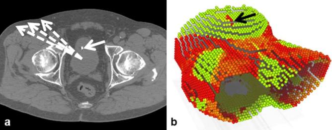
Illustration of the approach to identify potential ultrasound transducer positions: (a) example CT slice, (b) maximum intensity projection from PTV centroid. The dashed arrows illustrate the projections starting at the PTV centroid while the solid arrows highlight a landmark seen in the projection. Green/bright areas in the projection indicate positions for which the line to the PTV is not containing large Hounsfield units. PTV, planning target volume.
Treatment planning
In principle, robotic beam placement would allow beam delivery from infinite directions around the patient and with arbitrary orientation. In practice, the number of beam directions is limited to a discrete set of points (beam nodes) located above the treatment couch. For each beam node, beams pointing towards the PTV are considered. Different collimators can be used to shape the beam’s aperture, including cylinder collimators, the IRIS collimator and an MLC. For the purpose of our analysis we consider circular beams shaped by the IRIS collimator.26 A direct aperture optimization approach is then used to compute the beam weights.
Given the large number of potential combinations of beam node, beam orientation and diameter it is not feasible to consider all beams during optimization. Hence, we adopt the approach followed by the clinical treatment planning system and generate the beams in a heuristic fashion. Essentially, beam nodes and collimator sizes are sampled from uniform probability distributions while the orientation is drawn from a distribution favouring beams pointing closer to the surface of the PTV. Generally, such beams may pass through the ultrasound transducer and the robot holding it, which would render the beam less effective and complicate dose computation. Particularly, the exact pose of robot and transducer might not be known during planning, as the placement of the transducer could deform the abdominal surface in order to achieve good image quality. Moreover, during motion compensation the beams would move relative to the ultrasound transducer. Both effects could result in a substantial change in the delivered dose if a beam passing close to the robot is eventually blocked during treatment.
To avoid collisions of the beams with the ultrasound robot and transducer, we extend the beam generation. The transducer motion on the abdominal surface and the beam motion cannot be predicted during treatment planning. Hence, we consider a safety margin to account for this uncertainty. For each beam node, we first compute the projection of the robot and transducer onto a plane normal to the direction from the node to the centroid of the PTV. In this plane we establish the distance transform to the outer edge of the projection. During beam generation, for each beam we compute the point where its centre line intersects the projection plane for the respective node. Moreover, we also compute the effective beam radius in that plane from our dose model. From the distance transform we obtain whether the point of intersection is closer to the projection’s outer edge than beam radius plus safety margin, i.e. whether the beam could be partially blocked by robot or transducer. In this case we discard the beam and continue sampling beams until we generated the desired number of candidate beams. Figure 3 summarizes the setup for motion compensation we consider. Note that the ultrasound images would only need to provide the relative motion of some pattern or landmarks distinguishable by a computer program to realize motion compensation similar to the Synchrony (Accuray, Sunnyvale, CA) system. The figure also illustrates the use of the distance transform to test for collisions. See Figure 4 for an illustration of actual projections with the red and white lines denoting the first values of the distance transform.
Figure 3.
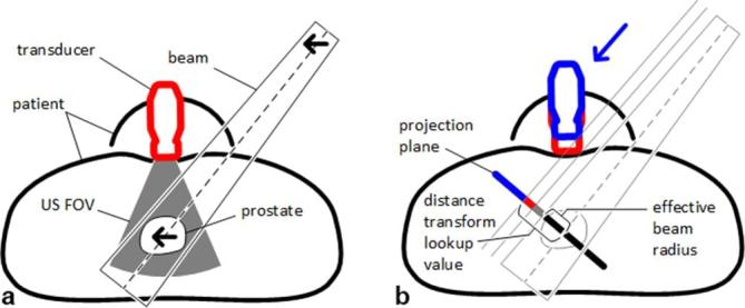
Illustration of ultrasound motion compensation. (a) shows the general setup with patient, prostate, ultrasound transducer, ultrasound FOV, and a treatment beam. Note that the prostate is moving within the FOV and that relative motion detected by ultrasound is compensated by the same relative motion of the beam (arrows). (b) illustrates the margins and the use of the distance transform to detect collision. The arrow denotes the projection, with the blue part of the projection representing the transducer in the planning pose. Red and gray projections represent margins accounting for transducer and beam motion, respectively. The effective beam radius plus the margin results in the lookup value for the distance transform, i.e. if the value of the distance transform for the point where the beam’s centre line intersects with the projection plane is larger or equal to the lookup value, there is no collision. FOV, field of view.
Figure 4.
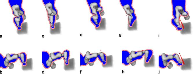
The 10 robot poses considered for treatment planning relative to a volume rendering of the CT, with (a–j) showing poses 1–10, respectively. A (red) sphere denotes the beam node for which the blue projection was computed. The (red) lines around the projection illustrate the result of the distance transform used to remove overlapping beams. Note that the transform is computed to include the largest expected effective radius.
Considering the set of candidate beams and their respective dose deposition coefficients in voxels of PTV and organs at risk (OAR) we establish an optimization problem based on linear programming.27 For each OAR and the PTV we define strict upper dose constraints and the objective function is defined to minimize the underdosing in PTV voxels, i.e. to maximize coverage of the PTV with the desired dose. Two SHELL structures were defined as virtual OAR to maintain the conformality of the dose distribution to the target. Essentially, SHELLs contain a set of points on a dilated PTV surface and maintain the dose gradient around the PTV. A further constraint limits the total monitor units. Note that the strict constraints imply that we can directly compare the objective values for different treatment plans. Moreover, typically only a small subset of all candidate beams has a weight larger than zero after optimization, i.e. the optimization effectively selects the set of treatment beams. To study the effect of integrating the ultrasound robot we run multiple optimizations on each set of patient data. This is facilitated using an in-house treatment planning system allowing to define treatment planning workflows which can then be optimized in batch mode.
Patient data
We studied data sets of 10 prostate patients previously treated with the CyberKnife. The PTVs included the prostate and had volumes ranging from 52.7 cm³ to 115.4 cm³. The key planning data including CT image, contours, the set of beam nodes and the physics data underlying the dose calculations were imported into our planning system. To achieve a comparable starting point, we specified constraints for the PTV, the rectum, the bladder and two SHELL structures to maintain a conformal dose distribution. The SHELL structures are dilated versions of the PTV surface at 3 and 9 mm distance from the PTV that control the dose gradient in all directions. We consider a hypofractionated protocol for prostate treatments with the CyberKnife delivering a prescribed dose of 36.25 Gy in 5 fractions.28 Accordingly, the maximum dose constraint for the PTV was set to 40.5 Gy. Our constraints on rectum and bladder were more conservative at 36 Gy maximum dose while the monitor unit constraint was set at 40,000 MU, allowing for rather conformal dose distributions, i.e. such that the plan quality is not dominated by the monitor unit constraint. Note that the key aspect of our study was the effect of adding an ultrasound robot and using its kinematic redundancy. We compare the treatment plans with respect to the optimization problem as seen by the planning system. To obtain a consistent base line plan for all patient cases, we relaxed the low dose conformality by adjusting the constraint on the SHELLs until a coverage of 95% at 36.25 Gy was achieved. All dose computations were performed on the planning grid of 3 × 3 × 3 mm³.
Experiments
Feasibility of robot setup and calibration was studied using an ultrasound phantom (FAST Exam Real Time Ultrasound Training Model, CAE Healthcare, Redmond, WA). The main objective of this step was to explore whether the ultrasound images would actually cover the relevant structures, i.e. natural or artificial landmarks within the prostate. To examine whether the kinematic redundancy of the ultrasound robot can help to offset the reduction of beam directions for a prostate SBRT we considered a beam node set forming the union of all nodes of the 10 patient cases. For each patient case and each of the 10 general robot poses shown in Figure 4, we considered the three distinct elbow configurations illustrated in Figure 5a–c, and the intersection of the projections of all three elbow configurations as shown in Figure 5d. The four cases are subsequently called “left”, “up”, “right” and “combined”. Moreover, three different safety margins of 10, 20 and 35 mm were considered. Each planning experiment was repeated 30 times to account for the heuristic beam generation. Additionally, for each patient we ran 30 experiments without the ultrasound robot to generate reference treatment plans. In total, 36,300 treatment plans have been computed.
Figure 5.
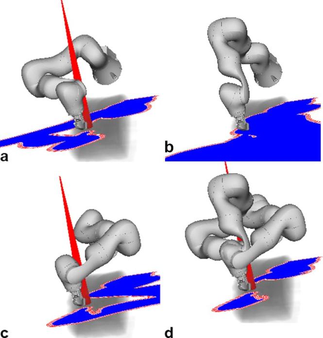
Illustration of the effect of the robot’s kinematic redundancy on the beam selection. (a–c) show the projections for the same ultrasound transducer pose and the same beam node but the elbow in a left, up and right position. Note that the beam is blocked in (b). Considering that the robot could move the elbow without changing the ultrasound transducer pose, we only need to remove beams that overlap with the intersection of the projections as illustrated in subfigure (d).
RESULTS
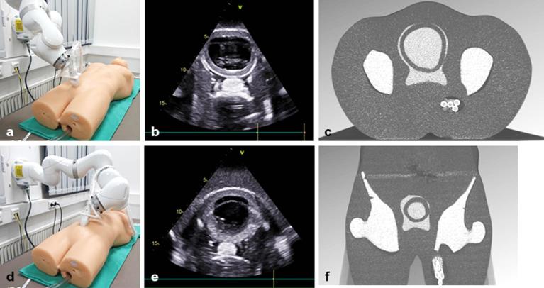
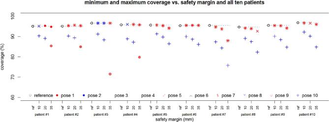
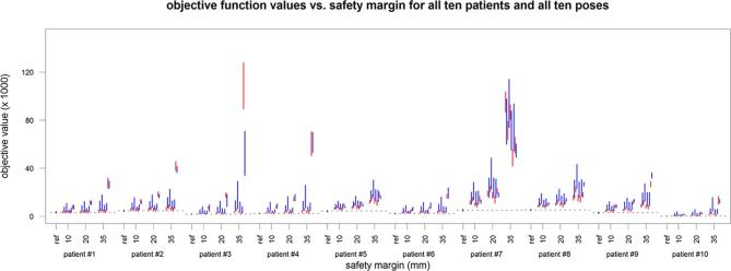
Figure 6 shows the system setup in the lab, illustrating how the robot realizes two different ultrasound transducer poses on the surface of the phantom (left). The ultrasound image and the respective CT slices are shown for each pose (centre, right). This demonstrates that ultrasound coordinates can be transformed into CT coordinates. Figures 7 and 8 summarize the planning results with respect to coverage and objective value for all 10 patient cases, the different margins and the different ultrasound robot poses. Figure 9 shows the dose volume histograms for all plans for a 20 mm margin and for PTV, rectum and bladder, respectively.
Figure 6.
Illustration of ultrasound transducer placement for two different viewports towards the target region (protate, bladder): (a,d) transducer position with respect to the abdominal surface; (b,e) the respective ultrasound images; (c,f) cutting planes through the CT obtained by transforming the ultrasound image plane to robot coordinates and then to CT coordinates using the ultrasound-to-robot and robot-to-surface calibrations.
Figure 7.
Coverage as the planning objective with respect to the different safety margins for all 10 patient cases and all 10 poses. The plotted values represent the mean over 30 repeated planning experiments. For clarity, only the minimum and maximum value over the different poses and the different elbow configurations are shown. Results are given for all 10 patient cases (from left = patient 1 to right = patient 10).
Figure 8.
The objective function value for the 10 patient cases (from left = patient 1 to right = patient 10) and the 10 poses (denoted by the blue and red from left = pose 1 to right = pose 10) in comparison to the respective reference values given in black. The lines represent the 25 to 75 quantile range and include the four different robot configurations.
Figure 9.
Dose-volume histograms for (a) PTV, (b) rectum and (c) bladder. The figure summarizes all dose distributions for a margin of 20 mm. Blue lines correspond to the reference plans, red line correspond to the combined elbow configuration and black lines correspond to all remaining plans. The figure illustrates that the PTV coverage for the combined elbow configurations is typically higher than for other plans while the OAR dose are not compromised. OAR, organs at risk; PTV, planning target volume.
Table 1 motivates the use of three elbow configurations in our analysis. The table shows the number of blocked beams for the three distinct poses elbow left, up and right, and for combinations of left and right, and left and up and right, respectively. The percentage of blocked beams when all integer elbow angles in between are considered is given for comparison. For this comparison we consider elbow angles from −90 degrees to 90 degrees for all robot poses. The elbow up configuration results in the fewest beams blocked for a single configuration. A combination of left, up and right configurations results in a substantial decrease in the number of blocked beams. A further small reduction results from considering all integer beam angles.
Table 1.
The mean percentage (μ) and standard deviation (σ) of blocked beams for one candidate beam set of the 10 patient cases, the 10 poses and the elbow left, up and right configurations, and for combinations of left/right and left/up/right, and all integer angles from left to right, respectively
| Pose | Left | Up | Right | Left, right | Left, up, right | All angles | ||||||
| μ | σ | μ | σ | μ | σ | μ | σ | μ | σ | μ | σ | |
| 1 | 40.34 | 2.06 | 36.12 | 1.77 | 35.58 | 1.90 | 28.87 | 2.04 | 28.46 | 2.03 | 27.25 | 1.95 |
| 2 | 27.00 | 1.94 | 28.04 | 2.06 | 33.48 | 2.51 | 24.52 | 1.95 | 24.47 | 1.93 | 24.01 | 1.90 |
| 3 | 41.32 | 2.69 | 36.73 | 2.13 | 39.29 | 2.65 | 32.99 | 2.91 | 32.06 | 2.79 | 30.73 | 2.66 |
| 4 | 31.46 | 2.64 | 32.93 | 2.48 | 39.57 | 3.14 | 29.77 | 2.50 | 29.31 | 2.36 | 28.87 | 2.36 |
| 5 | 44.62 | 2.53 | 40.99 | 2.61 | 37.69 | 2.54 | 30.62 | 2.68 | 30.59 | 2.64 | 29.40 | 2.53 |
| 6 | 27.56 | 2.54 | 27.82 | 2.89 | 31.08 | 3.17 | 23.41 | 3.10 | 23.37 | 3.08 | 22.99 | 2.95 |
| 7 | 35.59 | 2.35 | 35.34 | 0.98 | 37.61 | 0.95 | 26.16 | 1.85 | 25.82 | 1.68 | 24.62 | 1.32 |
| 8 | 27.82 | 1.15 | 28.42 | 0.76 | 33.29 | 1.93 | 22.71 | 0.72 | 22.66 | 0.73 | 22.04 | 0.67 |
| 9 | 51.11 | 5.74 | 39.71 | 7.39 | 36.48 | 8.54 | 34.16 | 8.27 | 32.47 | 7.54 | 30.07 | 6.95 |
| 10 | 28.55 | 7.66 | 27.89 | 8.78 | 28.39 | 9.07 | 26.52 | 7.84 | 26.32 | 7.93 | 25.48 | 7.61 |
| Mean | 35.54 | 3.13 | 33.40 | 3.19 | 35.25 | 3.64 | 27.97 | 3.39 | 27.55 | 3.27 | 26.55 | 3.09 |
Table 2 gives further details on how the different elbow configurations correspond to the worst-case coverage over all 10 patient cases and for a safety margin of 20 mm. Considering that the worst-case coverage for the combined elbow configurations for pose 7 is largest, Table 3 compares the coverages obtained for this combination to the reference values and the best plan including the ultrasound robot for all 10 patients.
Table 2.
Minimum coverage over all 10 patient data sets, for all 10 poses, the three elbow configurations and the combined configuration, and a safety margin of 20 mm
| Pose | Right | Left | Up | Combined | ||||
| μ | σ | μ | σ | μ | σ | μ | σ | |
| 1 | 91.5 | 0.8 | 92.5 | 0.5 | 91.1 | 0.7 | 92.0 | 0.6 |
| 2 | 90.9 | 0.9 | 92.0 | 0.7 | 87.4 | 0.8 | 92.9 | 0.7 |
| 3 | 90.3 | 0.8 | 91.1 | 1.0 | 90.7 | 0.7 | 91.6 | 0.8 |
| 4 | 89.3 | 0.9 | 90.8 | 0.7 | 84.3 | 0.9 | 91.1 | 0.9 |
| 5 | 91.7 | 0.8 | 92.8 | 0.8 | 91.6 | 0.6 | 92.3 | 0.8 |
| 6 | 90.8 | 0.8 | 92.4 | 0.6 | 87.7 | 0.7 | 92.8 | 0.8 |
| 7 | 93.0 | 0.8 | 93.6 | 0.8 | 91.4 | 0.6 | 93.5 | 0.6 |
| 8 | 90.8 | 0.9 | 92.0 | 0.6 | 87.4 | 0.7 | 93.2 | 0.7 |
| 9 | 90.2 | 0.6 | 89.3 | 0.8 | 90.5 | 0.7 | 91.1 | 0.7 |
| 10 | 90.8 | 0.7 | 91.0 | 0.7 | 88.4 | 0.6 | 91.7 | 0.8 |
Note. Values are given in percent, mean (μ) and standard deviation (σ) refer to the 30 repeated planning experiments. Bold numbers highlight the column-wise maximum.
Table 3.
Comparison of the reference plan (ref), the best result from all pose and elbow combinations (opt), and the plan for robot pose 7 combined (7/c), i.e. using the three elbow configurations
| Patient 1 | Patient 2 | Patient 3 | Patient 4 | Patient 5 | Patient 6 | Patient 7 | Patient 8 | Patient 9 | Patient 10 | |||||||||||
| μ | σ | μ | σ | μ | σ | μ | σ | μ | σ | μ | σ | μ | σ | μ | σ | μ | σ | μ | σ | |
| ref | 95.0 | 0.9 | 95.1 | 0.7 | 96.6 | 0.8 | 95.8 | 0.8 | 95.6 | 0.6 | 95.3 | 0.9 | 95.5 | 0.6 | 94.7 | 0.6 | 95.5 | 0.7 | 96.8 | 1.0 |
| opt | 95.3 | 1.0 | 95.6 | 1.0 | 96.6 | 1.0 | 96.0 | 1.0 | 95.4 | 1.0 | 95.5 | 1.0 | 93.7 | 0.9 | 93.9 | 0.9 | 95.3 | 1.0 | 96.6 | 1.0 |
| Δ | −0.2 | −0.5 | 0.0 | −0.2 | 0.3 | −0.2 | 1.7 | 0.8 | 0.2 | 0.2 | ||||||||||
| 7/c | 94.8 | 1.3 | 95.3 | 0.9 | 96.3 | 0.7 | 96.0 | 0.9 | 94.9 | 0.5 | 95.2 | 0.7 | 93.7 | 0.6 | 93.5 | 0.6 | 94.9 | 0.6 | 96.1 | 0.9 |
| Δ | 0.2 | −0.2 | 0.3 | −0.2 | 0.7 | 0.2 | 1.7 | 1.1 | 0.5 | 0.7 | ||||||||||
| p | 4.58E-01 | 3.78E-01 | 1.25E-01 | 3.49E-01 | 8.02E-06 | 3.94E-01 | 2.16E-15 | 1.83E-10 | 2.52E-03 | 6.52E-03 | ||||||||||
| vol | 67.1 | 93.2 | 82.3 | 81.1 | 109.7 | 70.3 | 115.4 | 86.1 | 87.5 | 52.7 | ||||||||||
Note. The Δ give the difference with respect to the reference plan, negative values indicate better coverage. The values for coverage are given in percent, mean (μ) and standard deviation (σ) refer to the 30 repeated planning experiments. The p-value for a t-test is provided with significant values highlighted in bold. Moreover, the PTV volume is given in cm.³ PTV, planning target volume.
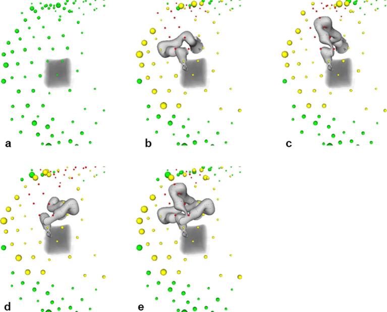
The blocking of nodes is illustrated in Figure 10, where colours of the spheres indicate whether nodes are unblocked (green), partially blocked (yellow) or completely blocked (red). The size of the spheres denotes the number of beams starting at the respective beam node. For the reference plan without the ultrasound robot, beams are delivered from many directions with a preference of inferior beam nodes (Figure 10a). When the ultrasound robot is added, some nodes are completely blocked while more beams start at nodes that are partially blocked (Figure 10b–d). Allowing for all three elbow configurations, the number of completely blocked beams decreases (Figure 10e).
Figure 10.
Beam node usage for a reference plan (a) ultrasound pose one and the elbow left (b) up (c) and right (d) and for the combination of the three elbow poses (e) Green spheres denote unblocked nodes with the size of the sphere representing the number of beams delivered from the respective node. Yellow and red spheres denote partially and completely blocked nodes, respectively.
Table 4 summarizes the number of completely and partially blocked nodes for pose 7. Results are presented for the different elbow configurations and all 10 patient cases. Note that the total number of nodes is 99 for all patient cases.
Table 4.
Comparison of the number of fully and partially blocked beam nodes for robot pose 7 and all 10 patients
| Plan | Right | Left | Up | Combined | PTV (cm³) | ||||||||||||
| Fully | Partially | Fully | Partially | Fully | Partially | Fully | Partially | ||||||||||
| μ | σ | μ | σ | μ | σ | μ | σ | μ | σ | μ | σ | μ | σ | μ | σ | ||
| 1 | 24.6 | 0.7 | 21.9 | 0.9 | 23.7 | 0.8 | 21.6 | 1.2 | 25.8 | 0.7 | 23.4 | 1.2 | 16.1 | 0.7 | 19.4 | 1.0 | 67.1 |
| 2 | 24.2 | 0.9 | 25.2 | 1.3 | 21.9 | 1.1 | 28.8 | 1.7 | 23.1 | 1.0 | 29.6 | 1.4 | 14.2 | 1.0 | 26.8 | 1.7 | 93.2 |
| 3 | 22.2 | 0.6 | 25.9 | 1.2 | 22.1 | 0.6 | 25.2 | 1.4 | 24.5 | 0.5 | 31.1 | 1.5 | 13.1 | 0.5 | 25.5 | 1.0 | 82.3 |
| 4 | 27.8 | 0.7 | 24.1 | 1.4 | 25.9 | 0.8 | 26.4 | 1.6 | 27.1 | 0.7 | 28.1 | 0.9 | 17.2 | 0.9 | 25.3 | 1.6 | 81.1 |
| 5 | 19.7 | 0.9 | 42.0 | 1.6 | 19.3 | 0.5 | 45.2 | 1.4 | 19.6 | 0.6 | 41.0 | 1.3 | 11.6 | 0.8 | 42.8 | 1.6 | 109.7 |
| 6 | 21.2 | 0.8 | 22.8 | 1.6 | 22.2 | 1.1 | 22.8 | 1.3 | 22.5 | 0.6 | 24.5 | 1.4 | 13.6 | 0.8 | 19.1 | 1.4 | 70.3 |
| 7 | 21.7 | 0.9 | 53.3 | 1.9 | 22.1 | 0.9 | 54.6 | 1.7 | 21.3 | 0.7 | 52.8 | 2.0 | 14.3 | 0.8 | 55.0 | 2.1 | 115.4 |
| 8 | 20.4 | 0.6 | 38.5 | 1.2 | 21.5 | 1.1 | 40.0 | 1.5 | 19.2 | 0.9 | 38.4 | 1.2 | 13.1 | 0.7 | 38.5 | 1.3 | 86.1 |
| 9 | 21.1 | 0.8 | 37.2 | 1.6 | 22.0 | 0.8 | 39.2 | 1.1 | 20.5 | 0.9 | 38.8 | 1.4 | 14.0 | 0.7 | 36.6 | 1.6 | 87.5 |
| 10 | 27.8 | 0.7 | 29.3 | 1.6 | 25.7 | 0.7 | 32.4 | 1.6 | 27.2 | 1.0 | 31.0 | 1.7 | 17.8 | 0.9 | 31.4 | 1.8 | 52.7 |
Note. Mean (μ) and standard deviation (σ) refer to the 30 repeated planning experiments. Moreover, the PTV volume is given in cm.³ PTV, planning target volume.
DISCUSSION
We present a setup to realize ultrasound image guidance during prostate SBRT using a kinematically redundant off-the-shelf robot to position the transducer. The key aspect of the current study is to investigate whether the robot’s freedom with respect to the elbow position can be used to minimize the impact of intrafractional robotic ultrasound on the plan quality. The results indicate that for prostate SBRT there exist ultrasound robot poses where the effect on the plan quality is small for the 10 studied patient cases, which represent a wide range of prostate volumes.
Considering Figure 7 it is clear that the robot can cause a substantial loss of coverage when placed in an unfavourable position. Figure 8 illustrates how this is related to the actual mathematical objective value, which represents the most direct measure for plan quality comparison in our study. As expected, the effect becomes more severe with a growing safety margin. While some poses are more prone to negatively affect the plan quality, it is not always the same pose leading to the minimal coverage. Likewise, there exist different poses which have the least effect on the coverage for each patient. Looking at Table 2, pose 7 is particularly interesting, as in the worst case it has the best coverage over all patients with a margin of 20 mm, particularly when the flexibility of the elbow position is used, i.e. for the combination of the “left”, “up” and “right” configurations. A further analysis of this pose and the combined beam set for all three elbow positions is given in Table 3. The coverage is typically close to the reference values and the best values obtained for any pose of the robot. Exceptions are patient 10, where another pose is yielding 0.5 percentage points more coverage on average, and patient 7, where pose seven combined represents the best coverage with robot but 1.7 percentage points below the reference value without robot.
In our study we try to isolate the effect of adding the ultrasound robot from other parameters that may affect plan quality. We maintain the same strict dose constraints for the maximum dose in PTV and OARs and for the total monitor units and we study the dose distribution on the optimization grid. Figure 9 shows dose volume histograms for all plans and PTV, rectum and bladder, respectively. The figure illustrates that all dose-volume constraints for the rectum are meet by all plans, with and without robot. For the bladder, three patient cases with larger prostates show a deviation with respect to the lower dose-volume constraint. Note that this is true for the plans with robot and for the reference plans. The reason is that we had to relax one constraint to achieve a baseline coverage of 95%, i.e. the deviation corresponds to a clinical decision to prioritize coverage over dose to an adjacent organ at risk. Figures 7–9 illustrate that the mathematical objective value and PTV coverage are suitable criteria to compare the plans.
A key aspect of our study is to evaluate to what extend the kinematic flexibility of the ultrasound robot can mitigate the impact of beam blocking on the treatment plan quality. Table 1 shows that the combination of elbow left-up-right configurations results in substantially fewer beams being blocked when compared to each single configuration. Moreover, a much larger set of all integer elbow angles between the left, up and right configurations only yields a smaller reduction in the percentage of blocked beams. This is interesting, as it may help reducing the search space for optimization. The effect of using the kinematic redundancy to avoid the blocking of beams is also illustrated by Figure 10 and further highlighted by Table 4. Both show that combining the three elbow configurations results in a substantial decrease in the number of completely blocked beam nodes compared to using each elbow configuration separately. Each single elbow configuration blocks 23.1 nodes on average while the combination blocks 14.5 nodes on average. Note that not all beam nodes are equally used in the reference plans, motivating our approach to position the ultrasound robot such that the actually useful beam directions remain unblocked.
Studying the results one needs to consider the heuristic nature of the candidate beam generation. Generally, a larger sample of candidate beams will result in better coverage during plan optimization. This is why we kept the number of beams at 6000 for all experiments. However, this results in more beams per node when blocking by the ultrasound robot is included, i.e. as fewer nodes are available. Given that some beam directions are preferable as indicated by Figure 10a, blocking of unfavourable beam nodes may therefore result in a larger choice of beams from promising directions. In turn this may improve the coverage, e.g. for patients 2 and 6 in Figure 7. Hence, a patient specific optimization including more configurations of the ultrasound robot could further improve the plan quality.
A further consideration regards the choice of the safety margin. The position of the ultrasound robot’s base and the configuration of the elbow have an impact on the dexterity when positioning the transducer on the abdominal wall. Hence, the actual robot pose may vary slightly, e.g. when the robot pushes the transducer into the tissue during force controlled placement. The placement of the ultrasound transducer would be semi-automatic, i.e. the demonstrated approach using the abdominal surface to place the robot would be complemented by small manual adjustments and automatic force controlled positioning. Moreover, the beam motion when compensating for a moving PTV needs to be taken into account. Prostate motion was reported to be within 6, 6 and 4 mm along the superior-inferior, anteroposterior, and left-right axes.29 In an actual treatment setting the pose of the CyberKnife and the ultrasound robot are known and hence the treatment could be stopped and setup repeated if the beams would be blocked. A 20 mm margin may therefore represent a reasonable choice to account for uncertainty with respect to the ultrasound robot and beam motion while avoiding unnecessary beam blocking. Note that the margin is small compared to the source-to-robot distance and that robot motion will be small, too. Therefore, the robot motion can be handled by adding a margin to a single projection of robot and transducer rather than simulating all possible pose changes of the transducer.
Another approach to integrate imaging would be transperineal ultrasound.30 For prostate cases this can be an interesting option if the target is visible throughout the treatment. The transabdominal approach is already established31 and may be more flexible and extended to other targets in the abdomen. Yet a different approach to integrate ultrasound imaging with radiation therapy devices is to limit its impact on beams passing through the ultrasound probe. While the delivery of beams through conventional ultrasound probes should be avoided,32 new “translucent” probes with a substantially reduced radio-opacity have been proposed.21 We agree that a completely X-ray translucent ultrasound imaging system would be a very interesting solution. However, it remains open whether perfect translucency for robot and transducer can be reached. Given the uncertainty with respect to robot and beam motion during treatment, any remaining “opacity” of the ultrasound guidance system could be addressed by the method we propose. In fact, our results show that for the CyberKnife even a readily available commercial robot and ultrasound transducer could be integrated while maintaining acceptable plan quality. Further studies are needed to evaluate the impact of potential beam blocking for Linac/MLC-based tracking.17,18 However, if the field orientations are optimized or rapid ARC delivery is used, similar results seem possible.
CONCLUSION
Ultrasound guidance for SBRT of the prostate using a kinematically redundant commercial robot can be realized while maintaining acceptable plan quality. Although the blocking of beam directions can have a substantial impact on the plan quality for treatments with the CyberKnife, the freedom in the ultrasound robot’s pose and elbow configuration can be used to offset the effect for most patients. We identified one pose that would result in acceptable plan quality for typical patients, particularly when considering that the benefit of non-invasive, non-ionizing and continuous motion tracking would outweigh a small loss in coverage. Considering that there is room for further patient specific robot pose optimization and that target tracking may facilitate tighter margins, robotic ultrasound represents an interesting alternative for intrafractional image guidance in SBRT of the prostate.
Footnotes
FUNDING: This study was partially funded by Deutsche Forschungsgemeinschaft (grants ER 817/1–1 and SCHL 1844/3-1).
Contributor Information
Stefan Gerlach, Email: stefan.gerlach@tu-harburg.de.
Ivo Kuhlemann, Email: kuhlemann@rob.uni-luebeck.de.
Floris Ernst, Email: ernst@rob.uni-luebeck.de.
Christoph Fürweger, Email: christoph.fuerweger@cyber-knife.net.
Alexander Schlaefer, Email: schlaefer@tuhh.de.
References
- 1.Keall PJ, Sawant A, Cho B, Ruan D, Wu J, Poulsen P, et al. Electromagnetic-guided dynamic multileaf collimator tracking enables motion management for intensity-modulated arc therapy. Int J Radiat Oncol Biol Phys 2011; 79: 312–20.https://doi.org/10.1016/j.ijrobp.2010.03.011 [DOI] [PMC free article] [PubMed] [Google Scholar]
- 2.Krauss A, Fast MF, Nill S, Oelfke U. Multileaf collimator tracking integrated with a novel x-ray imaging system and external surrogate monitoring. Phys Med Biol 2012; 57: 2425–39.https://doi.org/10.1088/0031-9155/57/8/2425 [DOI] [PubMed] [Google Scholar]
- 3.D'Souza WD, Naqvi SA, Yu CX, Cx Y. Real-time intra-fraction-motion tracking using the treatment couch: a feasibility study. Phys Med Biol 2005; 50: 4021–33.https://doi.org/10.1088/0031-9155/50/17/007 [DOI] [PubMed] [Google Scholar]
- 4.Depuydt T, Poels K, Verellen D, Engels B, Collen C, Haverbeke C, et al. Initial assessment of tumor tracking with a gimbaled linac system in clinical circumstances: a patient simulation study. Radiother Oncol 2013; 106: 236–40.https://doi.org/10.1016/j.radonc.2012.12.015 [DOI] [PubMed] [Google Scholar]
- 5.Schweikard A, Glosser G, Bodduluri M, Murphy MJ, Adler JR. Robotic motion compensation for respiratory movement during radiosurgery. Comput Aided Surg 2000; 5: 263–77.https://doi.org/10.3109/10929080009148894 [DOI] [PubMed] [Google Scholar]
- 6.Tong X, Chen X, Li J, Xu Q, Lin M-han, Chen L, et al. Intrafractional prostate motion during external beam radiotherapy monitored by a real-time target localization system. J Appl Clin Med Phys 2015; 16: 51–61.https://doi.org/10.1120/jacmp.v16i2.5013 [DOI] [PMC free article] [PubMed] [Google Scholar]
- 7.Kupelian P, Willoughby T, Mahadevan A, Djemil T, Weinstein G, Jani S, et al. Multi-institutional clinical experience with the Calypso system in localization and continuous, real-time monitoring of the prostate gland during external radiotherapy. Int J Radiat Oncol Biol Phys 2007; 67: 1088–98.https://doi.org/10.1016/j.ijrobp.2006.10.026 [DOI] [PubMed] [Google Scholar]
- 8.Fallone BG. The rotating biplanar linac-magnetic resonance imaging system. Semin Radiat Oncol 2014; 24: 200–2.https://doi.org/10.1016/j.semradonc.2014.02.011 [DOI] [PubMed] [Google Scholar]
- 9.Keall PJ, Barton M, Crozier S. On behalf of the Australian MRI-Linac Program,including contributors from the Ingham Institute,Stanford University, Illawarra Cancer Care Centre, Liverpool Hospital, Universities of Newcastle, Queensland, Sydney, Western Sydney, and Wollongong. Thethe Australian magnetic resonance imaging-linac program. Semin Radiat Oncol 2014; 24: 203–6. [DOI] [PubMed] [Google Scholar]
- 10.Lagendijk JJ, Raaymakers BW, Raaijmakers AJ, Overweg J, Brown KJ, Kerkhof EM, et al. MRI/linac integration. Radiother Oncol 2008; 86: 25–9.https://doi.org/10.1016/j.radonc.2007.10.034 [DOI] [PubMed] [Google Scholar]
- 11.Bohrer M, Schröder P, Welzel G, Wertz H, Lohr F, Wenz F, et al. Reduced rectal toxicity with ultrasound-based image guided radiotherapy using BAT (B-mode acquisition and targeting system) for prostate cancer. Strahlenther Onkol 2008; 184: 674–8.https://doi.org/10.1007/s00066-008-1837-z [DOI] [PubMed] [Google Scholar]
- 12.Cury FL, Shenouda G, Souhami L, Duclos M, Faria SL, David M, et al. Ultrasound-based image guided radiotherapy for prostate cancer: comparison of cross-modality and intramodality methods for daily localization during external beam radiotherapy. Int J Radiat Oncol Biol Phys 2006; 66: 1562–7.https://doi.org/10.1016/j.ijrobp.2006.07.1375 [DOI] [PubMed] [Google Scholar]
- 13.Fontanarosa D, van der Meer S, Bamber J, Harris E, O'Shea T, Verhaegen F. Review of ultrasound image guidance in external beam radiotherapy: I. Treatment planning and inter-fraction motion management. Phys Med Biol 2015; 60: R77–R114.https://doi.org/10.1088/0031-9155/60/3/R77 [DOI] [PubMed] [Google Scholar]
- 14.Bruder R, Ernst F, Schlaefer A, Schweikard A. A framework for Real-Time target tracking in radiosurgery using Three-dimensional ultrasound. Proceedings of the 25th International Congress and Exhibition on Computer Assisted Radiology and Surgery (CARS’11). Int J CARS 2011; 6: 306–7. [Google Scholar]
- 15.O'Shea TP, Garcia LJ, Rosser KE, Harris EJ, Evans PM, Bamber JC. 4D ultrasound speckle tracking of intra-fraction prostate motion: a phantom-based comparison with x-ray fiducial tracking using CyberKnife. Phys Med Biol 2014; 59: 1701–20.https://doi.org/10.1088/0031-9155/59/7/1701 [DOI] [PubMed] [Google Scholar]
- 16.O'Shea T, Bamber J, Fontanarosa D, van der Meer S, Verhaegen F, Harris E. Review of ultrasound image guidance in external beam radiotherapy part II: intra-fraction motion management and novel applications. Phys Med Biol 2016; 61: R90–R137.https://doi.org/10.1088/0031-9155/61/8/R90 [DOI] [PubMed] [Google Scholar]
- 17.Fast MF, O'Shea TP, Nill S, Oelfke U, Harris EJ. First evaluation of the feasibility of MLC tracking using ultrasound motion estimation. Med Phys 2016; 43: 4628–4633.https://doi.org/10.1118/1.4955440 [DOI] [PubMed] [Google Scholar]
- 18.Ipsen S, Bruder R, O'Brien R, Keall PJ, Schweikard A, Poulsen PR. Online 4D ultrasound guidance for real-time motion compensation by MLC tracking. Med Phys 2016; 43: 5695–5704.https://doi.org/10.1118/1.4962932 [DOI] [PubMed] [Google Scholar]
- 19.Schlosser J, Salisbury K, Hristov D. Telerobotic system concept for real-time soft-tissue imaging during radiotherapy beam delivery. Med Phys 2010; 37: 6357–67.https://doi.org/10.1118/1.3515457 [DOI] [PubMed] [Google Scholar]
- 20.Kuhlemann I, Bruder R, Ernst F, Schweikard A. WE-G-BRF-09: force- and Image-Adaptive strategies for Robotised Placement of 4D Ultrasound Probes. Med Phys 2014; 41: 523.https://doi.org/10.1118/1.4889502 [Google Scholar]
- 21.Schlosser J, Hristov D. Radiolucent 4D ultrasound imaging: system design and application to radiotherapy guidance. IEEE Trans Med Imaging 2016; 35: 2292–300.https://doi.org/10.1109/TMI.2016.2559499 [DOI] [PubMed] [Google Scholar]
- 22.Kuhlemann I, Jauer P, Ernst F, Schweikard A. Robots with seven degrees of freedom: Is theadditional DoF worth it? IEEE 2016 2nd International Conference on Control, Automation and Robotics (ICCAR) Hong kong, 2016; 80–4. [Google Scholar]
- 23.Kuhlemann I, Schweikard A, Jauer P, Ernst F, Robust inverse kinematics by configuration controlfor redundant manipulators with seven DoF, IEEE 2016 2nd International Conference on Control, Automation and Robotics (ICCAR) Hong Kong, 2016; 49–55. [Google Scholar]
- 24.Gerlach S, Kuhlemann I, Jauer P, Bruder R, Ernst F, Fürweger C, et al. Robotic ultrasound-guided SBRT of the prostate: feasibility with respect to plan quality. Int J Comput Assist Radiol Surg 2017; 12: 149–59.https://doi.org/10.1007/s11548-016-1455-7 [DOI] [PubMed] [Google Scholar]
- 25.Ernst F, Richter L, Matthäus L, Martens V, Bruder R, Schlaefer A, et al. Non-orthogonal tool/flange and robot/world calibration. Int J Med Robot 2012; 8: 407–20.https://doi.org/10.1002/rcs.1427 [DOI] [PubMed] [Google Scholar]
- 26.Echner GG, Kilby W, Lee M, Earnst E, Sayeh S, Schlaefer A, et al. The design, physical properties and clinical utility of an iris collimator for robotic radiosurgery. Phys Med Biol 2009; 54: 5359–80.https://doi.org/10.1088/0031-9155/54/18/001 [DOI] [PubMed] [Google Scholar]
- 27.Schlaefer A, Schweikard A. Stepwise multi-criteria optimization for robotic radiosurgery. Med Phys 2008; 35: 2094–103.https://doi.org/10.1118/1.2900716 [DOI] [PubMed] [Google Scholar]
- 28.King CR, Freeman D, Kaplan I, Fuller D, Bolzicco G, Collins S, et al. Stereotactic body radiotherapy for localized prostate cancer: pooled analysis from a multi-institutional consortium of prospective phase II trials. Radiother Oncol 2013; 109: 217–21.https://doi.org/10.1016/j.radonc.2013.08.030 [DOI] [PubMed] [Google Scholar]
- 29.Lovelock DM, Messineo AP, Cox BW, Kollmeier MA, Zelefsky MJ. Continuous monitoring and intrafraction target position correction during treatment improves target coverage for patients undergoing SBRT prostate therapy. Int J Radiat Oncol Biol Phys 2015; 91: 588–94.https://doi.org/10.1016/j.ijrobp.2014.10.049 [DOI] [PubMed] [Google Scholar]
- 30.Baker M, Behrens CF. Determining intrafractional prostate motion using four dimensional ultrasound system. BMC Cancer 2016; 16: 484https://doi.org/10.1186/s12885-016-2533-5 [DOI] [PMC free article] [PubMed] [Google Scholar]
- 31.Trichter F, Ennis RD. Prostate localization using transabdominal ultrasound imaging. Int J Radiat Oncol Biol Phys 2003; 56: 1225–33.https://doi.org/10.1016/S0360-3016(03)00269-4 [DOI] [PubMed] [Google Scholar]
- 32.Bazalova-Carter M, Schlosser J, Chen J, Hristov D. Monte Carlo modeling of ultrasound probes for image guided radiotherapy. Med Phys 2015; 42: 5745–56.https://doi.org/10.1118/1.4929978 [DOI] [PMC free article] [PubMed] [Google Scholar]


