Abstract
GATK HaplotypeCaller (HC) is a popular variant caller, which is widely used to identify variants in complex genomes. However, due to its high variants detection accuracy, it suffers from long execution time. In GATK HC, the pair-HMMs forward algorithm accounts for a large percentage of the total execution time. This article proposes to accelerate the pair-HMMs forward algorithm on graphics processing units (GPUs) to improve the performance of GATK HC. This article presents several GPU-based implementations of the pair-HMMs forward algorithm. It also analyzes the performance bottlenecks of the implementations on an NVIDIA Tesla K40 card with various data sets. Based on these results and the characteristics of GATK HC, we are able to identify the GPU-based implementations with the highest performance for the various analyzed data sets. Experimental results show that the GPU-based implementations of the pair-HMMs forward algorithm achieve a speedup of up to 5.47× over existing GPU-based implementations.
Keywords: Pair-HMMs forward algorithm, GPU acceleration, memory access, GATK HaplotypeCaller
Introduction
Next-generation sequencing (NGS) platforms are able to generate large amounts of DNA sequencing data at low cost, which provides great opportunities to deeply understand human genetics and identify genetic diseases.1 However, handling the large amount of DNA sequencing data produced by NGS platforms consumes much computation time. This is caused by the computationally intensive genomics analysis tools developed to help researchers study and investigate such DNA data. One such tool is GATK HaplotypeCaller (HC),2,3 which is a widely used variant caller tool in practice.
Variant callers are used to identify DNA variants by comparing a patient DNA sequencing data with a reference genome. Compared with many other variant callers, GATK HC is highly accurate in detecting variants. However, it comes at the expense of long execution time. Therefore, optimizing GATK HC to make it more efficient is important.
In GATK HC, the pair-HMMs forward algorithm (or PFA) accounts for a large percentage of the total execution time. It is applied to study the overall alignment probability of 2 sequences. Pair-HMMs forward algorithm is a computationally intensive algorithm in GATK HC, which is executed repeatedly millions of times for a typical data set.
To address this computational challenge, graphics processing units (GPUs) and field programmable gate arrays (FPGAs) are commonly used in many bioinformatics tools to accelerate the computationally intensive algorithms and improve their performance.4,5 Thus, this article accelerates PFA on GPUs to improve the performance of GATK HC.
The contributions of this article can be summarized as follows: (1) evaluate 2 approaches to implement PFA on GPUs, (2) present several GPU-based implementations of PFA based on these 2 approaches and compare their performance with different data sets, and (3) choose one implementation to integrate into GATK HC.
Background
GATK HaplotypeCaller
The GATK HC program consists of 4 main steps.6 (1) Active regions of the genome which have significant evidence of variation are determined. (2) For each active region, haplotypes are determined based on a de Bruijn–like graph and then haplotypes are realigned against the reference sequence using the Smith-Waterman algorithm. (3) For each active region, PFA is applied to perform a pairwise alignment of each read against each haplotype. (4) Bayes’ rule is applied to find the most likely genotypes.
Because the number of reads and the number of haplotypes for each active region are not the same, the number of read-haplotype pairs processed by PFA in the third step is different for each active region.
Pair-HMMs forward algorithm
Pair-HMMs forward algorithm in GATK HC is performed as shown in equations (1) to (3).7 and are the length of the read and the haplotype , respectively. is the overall alignment probability of 2 subsequences and when is aligned to . is the overall alignment probability of and when is aligned to a gap. is the overall alignment probability of and when is aligned to a gap.
Initialization:
| (1) |
Recurrence:
| (2) |
Termination:
| (3) |
, , , , , and are transmission probabilities that depend on the read position . In GATK HC, and are set to be constant. is the emission probability. Equation (4) shows how to calculate , where is the base quality score of the read at position i, and are the value of the read base at position i and the haplotype base at position , respectively:
| (4) |
The pseudocode of PFA is illustreated in Algorithm 1. The input data include 6 arrays and 2 integers. Among them, and are used to store read bases and haplotype bases; is used to store the base quality of the read; , , and are used to store transmission probabilities; and are the length of read and haplotype, respectively. The output is the overall alignment probability.
| Algorithm 1. Pseudocode of PFA in the GATK HaplotypeCaller. |
|---|
| 1: function PFA , , , , , , , |
| 2: |
| 3: |
| 4: |
| 5: |
| 6: for do |
| 7: for do |
| 8: if R [i]==H[j] then |
| 9: |
| 10: else |
| 11: |
| 12: end if |
| 13: |
| 14: |
| 15: |
| 16: end for |
| 17: end for |
| 18: return |
| 19: end function |
Algorithm 1 employs a 2-layer loop to calculate the elements of 3 matrices. Hence, the computational complexity of PFA is . As shown in Algorithm 1, , , and are only decided by the left, top-left, and top neighbor elements of the 3 matrices. This implies that the elements on the same antidiagonal do not have data dependency, which results in the inherent parallelism of PFA. Thus, elements on an antidiagonal are able to be calculated in parallel.
GPU architecture
Modern GPUs are widely applied to accelerate computationally intensive algorithms. For NVIDIA GPUs, there are many cores which are able to execute in parallel, and all of the cores are organized into several groups, which are called streaming multiprocessors.
NVIDIA proposes CUDA to help users to efficiently perform general computing. When a GPU kernel is launched by the host processor, there are many threads produced on the GPU. These threads on GPUs are managed by CUDA using a 2-level thread hierarchy: block and grid. Threads produced by a GPU kernel are grouped into many blocks and these blocks are grouped in a grid. Threads produced by different GPU kernels are in different grids. A GPU card can execute one or more grids and a streaming multiprocessors can execute one or more blocks.
Moreover, threads with consecutive thread indexes in the same block are bundled into groups, which are called warps. For many NVIDIA GPUs, the size of warp is 32. In addition, due to the Single Instruction Multiple Thread (SIMT) execution model, threads in a warp execute each instruction in lock step.
CUDA also introduces a memory hierarchy, which includes global memory, texture memory/cache, constant memory/cache, local memory, shared memory, and registers. Due to the characteristics of input data of PFA and implementation designed in this article, only the global memory, constant memory/cache, shared memory, and registers are used.
Figure 1 shows a simplified representation of the CUDA memory hierarchy. Constant memory is to store data which would not change during execution to reduce memory bandwidth. Global memory is accessed by all the threads on a GPU. As it resides on the device DRAM, the latency of the global memory access is high. Coalescing global memory accesses is useful to decrease the latency of total global memory accesses. For the GPU used in this article, the width of one global memory access is 128 bytes. If each thread in the same warp loads data (4 bytes, for example) stored at unordered different addresses from global memory, there would be 32 sequential global memory accesses in the worst-case situation. However, if all the accesses are coalesced, which means the data are stored at neighboring addresses, there will be only one global memory access.
Figure 1.
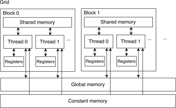
Simplified CUDA memory hierarchy.
However, registers and shared memory are owned by each streaming multiprocessor. Each block running on a streaming multiprocessor has a private space of the shared memory, which is only accessible to the threads in that block, whereas each thread running on the streaming multiprocessor has private registers, which are not accessible to other threads. Because shared memory and registers are scarce resources for each streaming multiprocessor, they limit the number of threads and blocks running on a streaming multiprocessor.
Related work
Most research published regarding the optimization of GATK HC focused on increasing the performance of PFA. Intel and IBM researchers adopt vector instructions on their respective processors8,9 to decrease the execution time by exploiting the inherent parallelism of PFA. There are also a couple of reports and publications on FPGA-based and GPU-based hardware acceleration of PFA.
Research on acceleration of PFA on FPGAs can be found in previous works.10–14 Ren et al10 used a systolic array to implement PFA on FPGAs, which exploits the inherent parallelism of PFA. Ito and Ohara11 proposed pipelined processing elements within a systolic array. Peltenburg et al12 reduced the overhead in the systolic array to improve the performance of the FPGA-based implementation of PFA. Altera13 mapped the algorithm to a 2-dimensional systolic array, whereas Huang et al14 mapped the algorithm to a ring-based systolic array.
Carneiro15 and Ren et al16 exploited GPU to accelerate PFA. Carneiro15 implemented PFA on several NVIDIA GPUs and reported the runtime of their implementations, without describing the implementation details. Ren et al16 proposed various GPU-based implementations of PFA by investigating 2 different acceleration approaches: intertask and intratask parallelization. In intertask parallelization, PFA is mapped to a single thread, such that each thread implements PFA independently. In intratask parallelization, PFA is mapped on multiple threads in a single block, instead of a single thread. It exploits the inherent parallelism of PFA, reducing the computational complexity of the algorithm to . However, it decreases the number of instances of PFA running in parallel on GPUs.
In this article, we analyze these 2 acceleration approaches in detail and compare the performance of several implementations of each approach using various data sets. Compared with the GPU-based implementation on NVIDIA Tesla K40 reported by Huang et al,14 our implementations are up to 5.47× faster. Moreover, one GPU-based implementation of PFA is selected to integrate into GATK HC.
Methods
First, we present the general design of the GPU-based GATK HC implementation. We then focus on the 2 GPU acceleration approaches and describe their implementations in detail.
General design
Figure 2 shows a block diagram of the GPU-based GATK HC. On the host PC, data sets of read-haplotype pairs are produced during the execution of GATK HC. The size of the data sets is variable, ranging from a couple to 100 000s of pairs depending on the input DNA data. When a data set is produced, the host preprocesses the data set, copies the data set to GPU, launches the GPU kernel to execute PFA, and then copies the results back.
Figure 2.
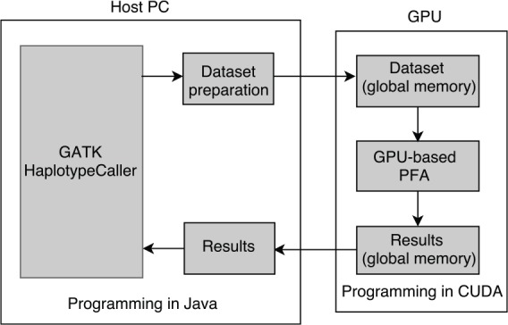
Block diagram of the GPU-based GATK HC implementation. GATK HC indicates GATK HaplotypeCaller; GPU, graphics processing unit.
On the GPU, threads load the data set from the global memory, execute PFA independently or cooperatively, and write the results to the global memory.
In addition, as CUDA is not able to communicate with JAVA directly, JCUDA is used to connect the JAVA and CUDA code.
Intertask implementations
In the intertask approach, each thread implements PFA independently. The execution trace of each thread is similar to that described in Algorithm 1. However, extra operations are added to take advantage of the CUDA memory hierarchy.
We first present the naive implementation of the intertask approach, the pseudocode of which is illustrated in Algorithm 2. As shown in Algorithm 2, each thread exploits a 2-level loop to calculate the elements of the matrices.
| Algorithm 2. Pseudocode of the naive implementation of the intertask approach. |
|---|
| procedure PFA(, , , , , , , ) |
| for do |
| for do |
| if then |
| else |
| end if |
| if then |
| else |
| end if |
| if then |
| end if |
| end for |
| end for |
| return |
| end procedure |
Due to the limitations of the shared memory and registers size on the GPU, each thread cannot load the input data into the shared memory and registers in advance. All of the input data are loaded into the shared memory and registers when they are being processed. To decrease the number of global memory accesses required by the input data, the outer loop of the 2-level loop iterates through the read bases and the inner loop iterates through the haplotype bases. In this way, the base quality score and the transmission probabilities (, , and ) of the read are loaded only once. Otherwise, these data are loaded many times.
Because each element is decided by the left, top-left, and top neighbor elements of the matrices, the intermediate results of PFA do not need to be stored for the entire duration of the execution time. As such, each thread uses 3 registers (, and ) to store the left neighbor elements, a register to store the result of a series of calculations of the top-left neighbor elements, and 3 vectors (, , and ) in the global memory to store the top neighbor elements. Using avoids loading the top neighbor elements from the global memory twice.
As shown in Algorithm 2, each iteration of the inner loop loads and stores 3 values from/into the 3 vectors, which requires global memory accesses. Because the latency of global memory access is very high, it is necessary to decrease the global memory accesses required by the intermediate results. Hence, the tiling technique17 is employed. The size of a tile is the number of the successive elements in one column covered by the tile.
The differences between the naive implementation and the tile-based implementation are as follows (the tile size is k): (1) the iteration times of the outer loop of the tile-based implementation is m/k and (2) each iteration of the inner loop of the tile-based implementation calculates a tile, which stands for k successive elements in a column, instead of one element. Figures 3 and 4 show the execution trace of the naive implementation and the tile-based implementation (the tile size is 2), which explain these 2 differences. In Figure 4, the iteration time of the outer loop is and each iteration of the inner loop calculates 2 elements.
Figure 3.
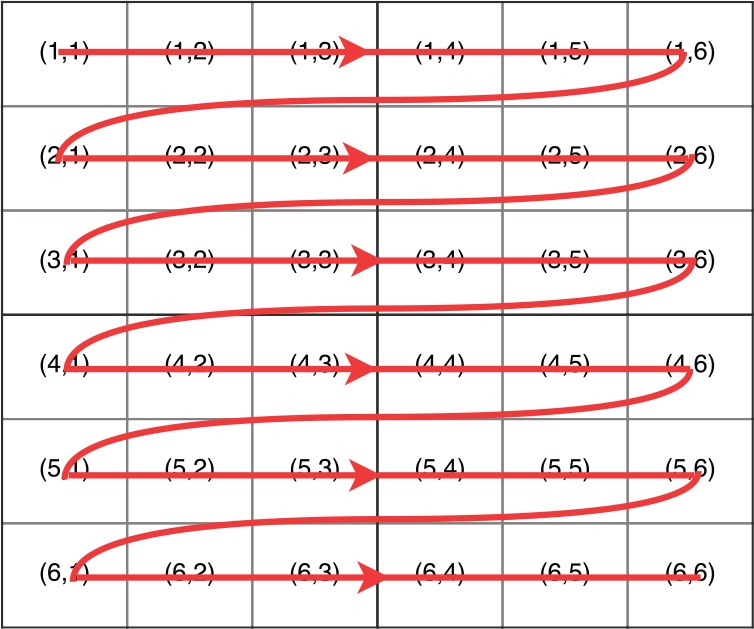
Execution trace of the naive implementation of the intertask approach.
Figure 4.
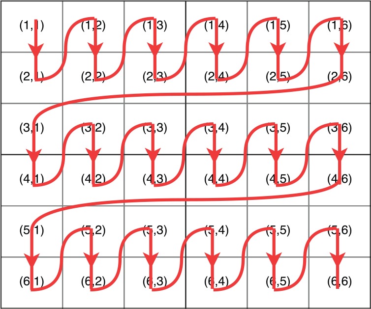
Execution trace of the tile-based implementation of the intertask approach (the tile size is 2).
In the inner loop of the tile-based implementation, 3 values from the 3 vectors are loaded to calculate the first element of a tile and 3 values of the last element of a tile are stored in the 3 vectors. Thus, the number of global memory accesses required by the intermediate results is using tiling technique.
However, the cost of reducing the global memory accesses required by the intermediate results is that each thread uses more shared memory and registers to store left neighbor elements of each tile.
Data set preparation
To better use the GPU computation capabilities, the data sets need to be converted before transferring them to the GPU.
Although for the intertask approach all threads implement PFA independently, if the iteration numbers of the outer loop and the inner loop of each PFA are not the same, threads in a warp need to wait for each other because of the SIMT execution model. Thus, the data sets are sorted first according to the length of reads and then according to the length of haplotypes.
After sorting, 32 read-haplotype pairs are processed by 32 threads in the same warp. To coalesce global memory accesses of the input data, each group of 32 read-haplotype pairs is stored in an interlaced fashion.
Figure 5 shows how the read bases and haplotype bases are stored. Take haplotypes for example. We write the first 4 characters of the first haplotype, after which write the first 4 characters of the second haplotype, and so on. This way, the first 4 characters of 32 haplotypes make up 128 bytes, which could be loaded by one coalesced global memory access. For haplotypes shorter than the longest haplotype in the group, they are padded with dummy characters.
Figure 5.
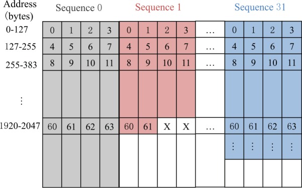
Writing bases of reads and haplotypes in an interlaced fashion.
The transmission probabilities and base quality score of 32 reads in each group are also written in an interlaced fashion. As they are single-precision floating point numbers, for each 128 bytes, we only write 1 number instead of 4 numbers. For reads shorter than the longest read in the group, the transmission probabilities and base quality score are padded with dummy numbers.
Intermediate results
For each thread, each iteration includes 6 global memory accesses required by the intermediate results. If these global memory accesses of 32 threads in a warp are noncoalesced, there will be global memory accesses in the worst-case situation.
As mentioned before, the intermediate results of each thread are stored in 3 vectors. To reduce global memory accesses, we use 3 big vectors to store the intermediate results of 32 threads in a warp, which are stored in an interlaced fashion. This way, each thread loads/writes the intermediate results from neighboring addresses. Because the intermediate results are single floating point numbers, 1 global memory access is able to satisfy the load/write requirements of 32 threads. Thus, there are global memory accesses for 32 threads in a warp instead of of each iteration.
Intratask implementations
In the intratask approach, threads in a block implement PFA cooperatively. The execute trace of each thread is different from that described in Algorithm 1.
We first present the naive implementation of the intratask approach. Depending on the number of threads in a block and the length of the read, there are 3 cases to analyze. We start with the simplest case, in which the number of threads in a block is equal to the length of the read. The execution trace of this case is shown in Figure 6A, in which the number of threads in a block and the length of the read is 4. As shown in Figure 6A, each thread calculates the elements in one column. For example, thread 0 (T0) calculates the elements in the first column. At each step, threads calculate the elements on an antidiagonal. For example, at step 3, T0 calculates , , and ; T1 calculates , , and ; and T2 calculates , , and . Because there are antidiagonals in the matrices, the computational complexity of the naive implementation is .
Figure 6.
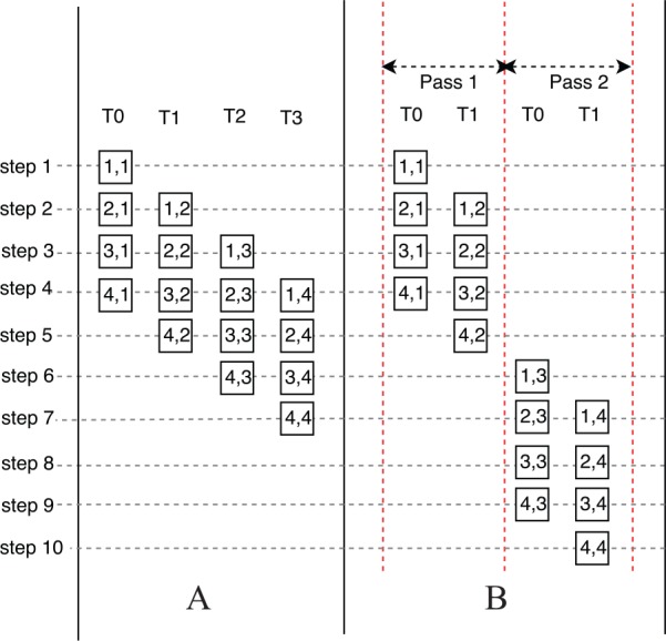
Execution trace of the naive implementation of the intratask approach (A) without passes (B) with passes.
The second case is that the number of threads in a block is bigger than the length of the read. The execution trace of the second case is similar to Figure 6A. However, there are some threads that remain idle during the whole execution period as the number of threads is bigger than the number of columns to be calculated.
The third case is that the number of threads in a block is smaller than the length of the read. The calculation is divided into several passes, which is shown in Figure 6B. The number of threads in a block is 2 and the length of the read is 4. Hence, there are in total 2 passes. In each pass, the execution trace is similar to Figure 6A.
For the intertask approach, because each block calculates one PFA, the input data of one PFA are able to be stored in the shared memory and registers in advance. Each read base and its corresponding base quality score and transmission probabilities are stored in the registers of each thread, whereas the haplotype bases are stored in the shared memory. The intermediate results produced by each thread are stored in 3 vectors in the shared memory. In addition, for the third case, 3 vectors in the global memory are used to store the intermediate results produced by the last thread of each pass, which will be used in the next pass.
For the intratask approach, the synchronization function is called to ensure that all the threads in the same block are synchronized and finish reading/writing the intermediate results in the shared memory. In each step, the synchronization function is called twice. Thus, the synchronization call will be called times in total. However, the cost of synchronization call is high because it makes threads in a block stall to wait for each other. There are 2 solutions to decrease the number of the synchronization function calls.
One solution is to exploit the tiling technique. In the tile-based implementation (the tile size is k), each thread calculates k elements in a column before a synchronization function is called. Figure 7 shows the execution trace of the tile-based implementation (the tile size is 2). As shown in Figure 7, each thread calculates 2 elements in each column every 2 steps and thus the synchronization function is called every 2 steps. In this way, there are only synchronization function calls in the tile-based implementation (the tile size is k). However, more shared memory and registers are used to store the intermediate results. Moreover, the number of execution steps of the tile-based implementation is more than that of the naive implementation. As shown in Figure 7, the execution steps of the tile-based implementation are 12, whereas the execution steps of the naive implementation would be only 9.
Figure 7.
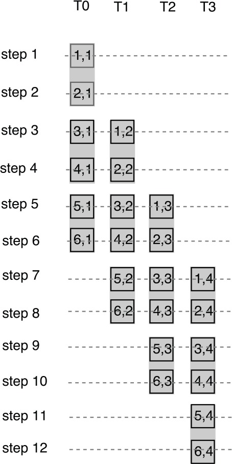
Execution trace of the tile-based implementation of the intratask approach (the tile size is 2).
The other solution is the warp-based implementation, in which the number of threads in a block is equal to the number of threads in a warp (32). In this way, threads in a warp implement PFA cooperatively. Because the threads in the same warp work in the SIMT execution model, there is no need to call synchronization function in the warp-based implementation. Moreover, because threads within a warp can use shuffle instructions to exchange data, the intermediate results produced by each thread are not stored in the shared memory. The only intermediate results stored in the shared memory are the intermediate results between passes for the third case.
However, the warp-based implementation cannot effectively use the resources on GPUs because the number of threads in a block is small. One method to solve this problem is to increase the number of warps in a block and make each warp implement PFA independently. For example, if the number of threads in a block is 256, there are 8 warps in the block and each warp implements PFA independently. In the improved warp-based implementation, the intermediate results between passes for the third case produced by each warp are stored in the global memory.
Data set preparation
In the intratask approach, the read bases, base score quality, and the transmission probabilities, which are loaded into the registers of each thread, are written into 6 vectors separately, whereas the haplotype bases, which are loaded into the shared memory, are written into char4 to reduce the global memory accesses.
Intermediate results
The intermediate results inside one pass are stored in the shared memory using 3 vectors, except for the (improved) warp-based implementations (which use shuffle instructions to exchange data), whereas the intermediate results between passes are stored in the global memory using 3 vectors, except for the warp-based implementation (which stores intermediate data in the shared memory).
Results and Discussion
Experimental setup
IBM Power System S823L (82478-42L) is used to perform all the experiments. This system has 2 IBM Power8 processors, each of which has 10 cores running at 3.6 GHz, 256 GB of DDR3 memory, and an NVIDIA Tesla K40 card. The NVIDIA Tesla K40 card has 2880 cores that run at up to 745 MHz and has a CUDA compute capability of 3.5.
We first compare the performance of these GPU-based PFA implementations with the synthetic and real data sets and then integrate the GPU-based PFA implementations into GATK HC 3.7 and compare the overall performance.
To evaluate these GPU-based PFA implementations, throughput is a key performance metric, which is measured by giga cell updates per second (GCUPS). For a data set of read-haplotype pairs, equation (5) defines how to calculate the value of GCUPS:
| (5) |
where is the runtime in seconds, is the number of the read-haplotype pairs in the data set, and are the length of read and haplotype, respectively. The runtime is the computation time of PFA on GPUs.
Implementations of intertask approach
For the tile-based implementations of the intertask approach, the length of reads would slightly affect the performance if it is not a multiple of the tile size. To be fair and find the maximum achievable speedup of every implementations, 6 types of synthetic data sets are used and the length of read and haplotype in each data set are different, as shown in Table 1. In addition, the number of the read-haplotype pairs of each data set is .
Table 1.
Synthetic data sets of the intertask implementations.
| 1 | 2 | 3 | 4 | 5 | 6 | |
|---|---|---|---|---|---|---|
| Read length | 24 | 48 | 72 | 96 | 120 | 144 |
| Haplotype length | 24 | 48 | 72 | 96 | 120 | 144 |
Figure 8 shows the throughput of 5 implementations of the intertask approach: naive, tile = 2, tile = 4, tile = 6, and tile = 8. As shown in Figure 8, the throughput of the naive implementation is the lowest over all the implementations. In addition, the throughput of the implementation with tile = 6 is the highest over all the implementations.
Figure 8.
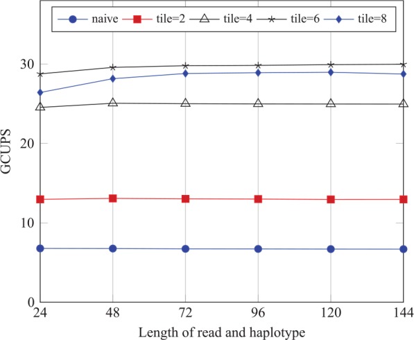
Performance comparison of the intertask implementation on the synthetic data sets.
We use NVIDIA profiling tools (NVVP) to find the performance bottleneck of these implementations. We run the implementations with data set 6. The profiling results are shown in Table 2. Table 2 shows that the global memory bandwidth reduces when the tile size increases. However, the registers per thread and shared memory per block increase when the tile size increases, which reduces the theoretical occupancy. In addition, the naive, tile = 2, and tile = 4 implementations are bounded by the global memory bandwidth; whereas the other 2 are bounded by the instruction and memory latency, which is caused by the low occupancy.
Table 2.
Profiling results of the intertask implementations on synthetic data set 8.
| Performance limitation | Global memory bandwidth, GB/s | Registers per thread | Shared memory per block, bytes | Theoretical occupancy, % | Achieved occupancy, % | |
|---|---|---|---|---|---|---|
| Naive | Memory bandwidth | 207 | 48 | 0 | 62.5 | 62.1 |
| Tile = 2 | Memory bandwidth | 201 | 72 | 4096 | 43.8 | 43.3 |
| Tile = 4 | Memory bandwidth | 193 | 73 | 8192 | 37.5 | 37.1 |
| Tile = 6 | Instruction and memory latency | 154 | 104 | 12 288 | 25 | 24.9 |
| Tile = 8 | Instruction and memory latency | 101 | 142 | 16 384 | 18.8 | 18.2 |
Table 2 shows that the implementation with tile = 6 strikes a trade-off between the decreasing global memory bandwidth requirements as tile size increases, on the one hand, and between the increasing requirements of the instruction and memory latency, on the other hand. This explains the reason why the throughput of the implementation with tile = 6 is the highest on the synthetic data sets.
Implementations of intratask approach
This section compares the performance of the naive, tile = 2, warp-based, and improved warp-based implementations of the intratask approach. Here, the block size of the naive and tile = 2 implementations is 128. Table 3 shows 26 types of synthetic data sets and the length of read and haplotype in each data set are different. Data sets 1 to 21 make no thread idle during each pass for the (improved) warp-based implementations, whereas data sets 22 to 26 make no thread idle during each pass for all the implementations.
Table 3.
Synthetic data sets of the intratask implementations (R and H stand for length of read and haplotype, respectively).
| 1 | 2 | 3 | 4 | 5 | 6 | 7 | 8 | 9 | |
|---|---|---|---|---|---|---|---|---|---|
| R | 32 | 32 | 32 | 32 | 32 | 32 | 32 | 32 | 64 |
| H | 32 | 64 | 96 | 128 | 160 | 192 | 224 | 256 | 64 |
| 10 | 11 | 12 | 13 | 14 | 15 | 16 | 17 | 18 | |
| R | 64 | 64 | 64 | 64 | 64 | 64 | 96 | 96 | 96 |
| H | 96 | 128 | 160 | 192 | 224 | 256 | 96 | 128 | 160 |
| 19 | 20 | 21 | 22 | 23 | 24 | 25 | 26 | ||
| R | 96 | 96 | 96 | 128 | 128 | 128 | 128 | 128 | |
| H | 192 | 224 | 256 | 128 | 160 | 192 | 224 | 256 |
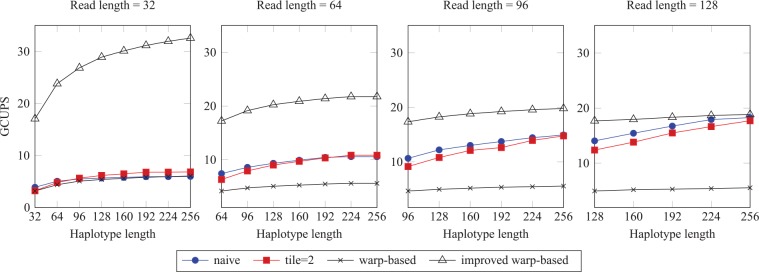
Figure 9 shows the throughput of 3 implementations of the intratask approach when the number of the read-haplotype pairs of each data set is . For the warp-based and improved warp-based implementations, if the length of read is the same, the throughput increases with the increase in the haplotype length. In contrast, if the haplotype length is the same, the throughput decreases with the increase in the read length, which is caused by the increased number of costly global memory accesses. In addition, the improved warp-based implementation achieves higher throughput than the warp-based implementation.
Figure 9.
Performance comparison of the intratask implementations on the synthetic data sets (size: ). GCUPS indicates giga cell updates per second.
As shown in Figure 9, the throughput of the naive and tile = 2 implementations increases with the increase in the read/haplotype length, which is not the case for the (improved) warp-based implementations. Compared with tile = 2 implementation, the naive implementation achieves higher throughput.
Table 4 shows the NVVP profiling results of the 4 implementations running with data set 26. As shown in Table 4, the shared memory bandwidth of the naive implementation is higher than that of the tile = 2 implementation, which is because that the tiling technique reduces shared memory accesses. However, because the tile = 2 implementation has more shared memory and registers to store the intermediate results, its theoretical occupancy is smaller than that of the naive implementation. As shown in Figure 9, the throughput of the tile = 2 implementation is smaller than that of the naive implementation, which indicates that the decrease in the occupancy outweighs the reduction in the number of synchronization calls. If the tile size continues to increase, the theoretical/achieved occupancy will continue to reduce, which results in the decreasing throughput.
Table 4.
Profiling results of the intratask implementations with synthetic data set 26 (warp* stands for the improved warp based).
| Performance limitation | Shared memory bandwidth, GB/s | Registers per thread | Shared memory per block, bytes | Theoretical occupancy, % | Achieved occupancy, % | |
|---|---|---|---|---|---|---|
| Naive | Memory bandwidth | 2213 | 32 | 2124 | 100 | 99.8 |
| Tile = 2 | Memory bandwidth | 2005 | 39 | 3660 | 75 | 74.9 |
| Warp | Instruction and memory latency | 362 | 32 | 6540 | 10.9 | 10.9 |
| Warp* | Compute | 262 | 44 | 2000 | 62.5 | 62.5 |
As shown in Table 4, the theoretical/achieved occupancy of the improved warp-based implementation is much bigger than that of the warp-based implementation, which is caused by the low GPU resources utilization of the warp-based implementation. Hence, the throughput of the improved warp-based implementation is higher than that of the warp-based implementation, as shown in Figure 9.
In Figure 8, the throughput of the intertask implementations is comparable when the length of the haplotype or read increases, whereas in Figure 9, the throughput of the intratask implementations increases when the length of the haplotype or read increases.
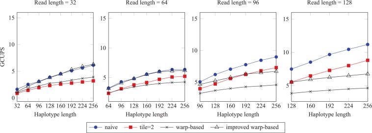
Figure 10 shows the throughput of the intratask implementations when the number of the read-haplotype pairs of each data set is reduced to only (instead of pairs used for Figure 9). In this figure, the naive implementation achieves the highest throughput for most of the data sets. This is because when the size of data set is small, the improved warp-based implementation does not have enough computation to fully use the GPU resources.
Figure 10.
Performance comparison of the intratask implementations on the synthetic data sets (size: 200).
Comparison with other implementations
We compared our GPU-based implementation with other implementations proposed in the previous works.13-15 The data set used is the “10s” data set.18 Despite its small size, this data set has published runtime baseline comparisons for different implementations and platforms.
Table 5 shows the performance of various implementations, including CPU, GPUs, multicores, and FPGAs. The runtime includes the data set preparation time, the computation time on GPU, and the data transfer time between host and GPU. As shown in Table 5, all the GPU-based implementations proposed in this article are faster than the Intel Xeon single core AVX implementation. Moreover, except for the naive intertask implementation, all the implementations proposed in this article are faster than the NVIDIA K40 GPU implementation proposed in the work by Huang et al.14
Table 5.
Performance comparison of various implementations on a “10s” data set.
| Implementations | Runtime, ms | Speedup |
|---|---|---|
| Java on CPU14 | 10 800 | 1× |
| C++ Baseline14 | 1267 | 9× |
| Inter Xeon AVX 1 Core14 | 138 | 78× |
| Intel Xeon 24 Cores14 | 15 | 720× |
| Alter OpenCL (Arria 10)13 | 2.8 | 3857× |
| PE Ring (Arria 10)14 | 2.6 | 4154× |
| NVIDIA Tesla K40 GPU14 | 70 | 154× |
| Naive intratask | 14.2 | 761× |
| Tile = 2 intratask | 15.5 | 696× |
| Warp based | 20.6 | 524× |
| Improved warp based | 12.8 | 843× |
| Naive intertask | 76.6 | 141× |
| Tile = 2 intertask | 45.1 | 239× |
| Tile = 4 intertask | 29.6 | 365× |
| Tile = 6 intertask | 26.4 | 409× |
| Tile = 8 intertask | 24.9 | 433.7× |
Our best case performance is the improved warp-based implementation. It is 5.47× faster than the K40 GPU implementation, 1.17× faster than the Intel Xeon 24 cores AVX implementation, and 843× faster than the original JAVA implementation. The table also shows that the FPGA-based implementations have the potential to achieve higher performance, albeit at the expense of long development time and the corresponding high design complexity and cost.
Real data set
In this section, 5 intertask implementations (naive, tile = 2, tile = 4, tile = 6, and tile = 8) and 4 intratask implementations (naive, tile = 2, warp-based, and improved warp-based) are compared using a real data set. To produce the real data set, we modified the source code of GATK HC 3.7 to output the read-haplotype pairs of each active region in the third step of the program “Determine likelihoods of the haplotypes”. For the modified GATK HC 3.7, chromosome 10 of the whole human data set G15512.HCC1954.1 is used to produce the real data set, which is divided into small chunks with each chunk containing the read-haplotype pairs of one active region. The size of each chunk ranges from 4 to 38 912.
In addition, 2 software-based implementations of PFA are provided for performance comparison: Power8 single core implementation and Power8 20 cores implementation. Both of them are written in the C++ programming language, optimized with the vector instructions and compiled with gcc O3 optimization. Moreover, the Power8 20 cores implementation exploits OpenMP to run on 20 cores.
In Table 6, for the GPU-based implementation, T1 includes the computation time on GPU and the data transfer time between CPU and GPU, T2 is the data set preparation time, and T3 is the total time, which is the sum of T1 and T2. For the software implementations, T3 is the total time and there is no data set preparation. In this section, T3 is the runtime t in equation (5) to calculate GCUPS.
Table 6.
Performance comparison of implementations on a real data set.
| Implementations | T1, s | T2, s | T3, s | Throughput (GCUPS) |
|---|---|---|---|---|
| Naive intratask | 46 | 53 | 99 | 2.60 |
| Tile = 2 intratask | 47 | 53 | 100 | 2.52 |
| Warp based | 81 | 51 | 132 | 1.91 |
| Improved warp based | 48 | 57 | 105 | 2.40 |
| Naive intertask | 701 | 73 | 774 | 0.33 |
| Tile = 2 intertask | 382 | 73 | 455 | 0.56 |
| Tile = 4 intertask | 238 | 75 | 312 | 0.81 |
| Tile = 6 intertask | 213 | 75 | 288 | 0.88 |
| Tile = 8 intertask | 217 | 73 | 290 | 0.87 |
| Power8 single core | — | — | 1161 | 0.22 |
| Power8 20 cores | — | — | 95 | 2.65 |
Abbreviation: GCUPS, giga cell updates per second.
Table 6 shows the performance of 11 implementations on the real data set. The naive intratask implementation is the fastest over all the GPU-based implementations. In addition, the 4 intratask implementations are faster than the 5 intertask implementations. It is mainly because when the number of the read-haplotype pairs in each chunk is small, the intertask implementations cannot use the GPU resources efficiently.
As shown in Table 6, the naive intratask implementation is faster than the improved warp-based implementation. This is because 82% of chunks in the real data include less than 200 read-haplotype pairs. Moreover, Figure 10 shows that when the size of the data set is reduced to 200 pairs, the naive implementation of the intratask approach is faster than the improved warp-based implementation for most of the synthetic data sets.
For the total time (T3), all the GPU-based implementations are faster than the Power8 single core implementation. Specifically, the naive intratask implementation is 11.73× faster than the Power8 single core implementation. However, the Power8 20 cores implementation is faster than all the GPU-based implementations. Regardless of the data set preparation time, the naive intratask implementation (46 s) is much faster than the Power8 20 cores implementation (95 s).
Integration into GATK HC
The GPU-based implementation of PFA with the highest performance for the real data set (which is the naive implementation of the intratask approach) is integrated into GATK 3.7. There are other 2 GATK HC implementations to be compared with: (1) GATK HC with the PFA implemented with JAVA (referred to as baseline), which is download from the GATK Web site and (2) GATK HC with the PFA running on the CPU optimized using vector instructions (referred to as Vector), the library of which is implemented by IBM.9 The data set is chromosome 10 of the whole human genome data set G15512.HCC1954.1.
Although GATK HC is able to run in single-thread and multithread mode, it usually runs in single-thread mode while executing several instances of GATK HC at the same time due to the inefficiency of the multithread mode of the program. Thus, we will only compare the performance of GATK HC running in single-thread mode.
As shown in Table 7, the baseline is slower than the other 2 implementations. Compared with the baseline, the vectorized GATK HC achieves 1.42× speedup and the GPU-based GATK HC achieves 1.71× speedup. In addition, the GPU-based GATK HC is 1.2× faster than the vectorized GATK HC.
Table 7.
Results of the GATK HC implementations.
| GATK HC | Total time, s | Speedup |
|---|---|---|
| Baseline | 8034.05 | — |
| Vector | 5655.96 | 1.42× |
| GPU | 4687.08 | 1.71× |
Abbreviations: GATK HC, GATK HaplotypeCaller; GPU, graphics processing unit.
Conclusions
In GATK HC, PFA accounts for a large percentage of the total execution time. This article proposes to accelerate PFA on GPUs to improve the performance of GATK HC. Due to the characteristics of PFA, there are 2 approaches to implement it on GPUs: intertask and intratask. This article first presented several GPU-based implementations of PFA for each approach. We executed all the implementations on an NVIDIA Tesla K40 card and compared their performance using different synthetic and real data sets. Experimental results show that our solution achieves a speedup up to 5.47× over other GPU-based implementations. In addition, the naive implementation of the intratask approach is integrated into GATK HC, resulting in an overall speedup of 1.71× over the baseline implementation and 1.2× over the vectorized GATK HC on a single core.
Acknowledgments
The authors wish to thank the Texas Advanced Computing Center (TACC) at the University of Texas at Austin and IBM for the giving access to the IBM Power8 machines used in this paper.
Footnotes
Funding:The author(s) received no financial support for the research, authorship, and/or publication of this article.
Declaration of Conflicting Interests:The author(s) declared no potential conflicts of interest with respect to the research, authorship, and/or publication of this article.
Author Contributions: SR designed and performed the experiments, analyzed the data, and wrote the manuscript. All the authors jointly developed the structure and arguments for the paper, made critical revisions and approved final version.
References
- 1. Shendure J, Ji H. Next-generation DNA sequencing. Nat Biotech. 2008;26:1135–1145. [DOI] [PubMed] [Google Scholar]
- 2. McKenna A, Hanna M, Banks E, et al. The genome analysis toolkit: a MapReduce framework for analyzing next-generation DNA sequencing data. Genome Res. 2010;20:1297–1303. [DOI] [PMC free article] [PubMed] [Google Scholar]
- 3. DePristo M, Banks E, Poplin R, et al. A framework for variation discovery and genotyping using next-generation DNA sequencing data. Nature Genet. 2011;43:491–498. [DOI] [PMC free article] [PubMed] [Google Scholar]
- 4. Lu M, Zhao J, Luo Q, et al. GSNP: a DNA single-nucleotide polymorphism detection system with GPU acceleration. Paper presented at: 2011 International Conference on Parallel Processing; September 13–16, 2011; Taipei, Taiwan. [Google Scholar]
- 5. Liu CM, Wong T, Wu E, et al. Soap3: ultra-fast GPU-based parallel alignment tool for short reads. Bioinformatics. 2012;28:878. [DOI] [PubMed] [Google Scholar]
- 6.HaplotypeCaller call germline SNPs and Indels via local re-assembly of haplotypes. https://software.broadinstitute.org/gatk/documentation/tooldocs/current/org_broadinstitute_hellbender_tools_walkers_haplotypecaller_HaplotypeCaller.php. Accessed February 22, 2018.
- 7. Carneiro M, Poplin R, Biagioli E, et al. Enabling high throughput haplotype analysis through hardware acceleration. https://github.com/MauricioCarneiro/PairHMM/tree/master/doc. Accessed May 15, 2017.
- 8. Proffitt A. Broad, Intel announce speed improvements to GATK powered by Intel optimizations. http://www.bio-itworld.com/2014/3/20/broad-intel-announce-speed-improvements-gatk-powered-by-intel-optimizations.html. Accessed February 22, 2018.
- 9. VdAuwera G. Speed up HaplotypeCaller on IBM Power8 systems. https://software.broadinstitute.org/gatk/blog?id=4833. Accessed March 15, 2017.
- 10. Ren S, Sima VM, Al-Ars Z. FPGA acceleration of the pair-HMMs forward algorithm for DNA sequence analysis. Paper presented at: 2015 IEEE International Conference on Bioinformatics and Biomedicine (BIBM); November 9–12, 2015; Washington, DC, pp. 1465-1470. New York, NY: IEEE. [Google Scholar]
- 11. Ito M, Ohara M. A power-efficient FPGA accelerator: systolic array with cache-coherent interface for pair-HMM algorithm. Paper presented at: 2016 IEEE Symposium in Low-Power and High-Speed Chips (COOL CHIPS XIX); July 7, 2016; Yokohama, Japan, pp. 1–3. New York, NY: IEEE. [Google Scholar]
- 12. Peltenburg J, Ren S, Al-Ars Z. Maximizing systolic array efficiency to accelerate the PairHMM forward algorithm. Paper presented at: 2016 IEEE International Conference on Bioinformatics and Biomedicine (BIBM); December 15-18, 2016; Shenzhen, China, pp. 758–762. New York, NY: IEEE. [Google Scholar]
- 13. Altera. Accelerating genomics research with OpenCL and FPGAs. https://www.altera.com/content/dam/altera-www/global/en_US/pdfs/literature/wp/wp-01262-accelerating-genomics-research-with-opencl-and-fpgas.pdf. Accessed February 22, 2018.
- 14. Huang S, Manikandan GJ, Ramachandran A, et al. Hardware acceleration of the pair-HMM algorithm for DNA variant calling. Paper presented at: Proceedings of the 2017 ACM/SIGDA International Symposium on Field-Programmable Gate Arrays, FPGA ’17; February 22-24, 2017; Monterey, CA, pp. 275–284. New York, NY: ACM. [Google Scholar]
- 15. Carneiro M. Accelerating variant calling. https://hpc.mssm.edu/files/Carneiro_workshop.pdf. Accessed March 15, 2017.
- 16. Ren S, Bertel K, Al-Ars Z. Exploration of alternative GPU implementations of the pair-HMMs forward algorithm. Paper presented at: 2016 IEEE International Conference on Bioinformatics and Biomedicine (BIBM); December 15-18, 2016; Shenzhen, China, pp. 902–909. New York, NY: IEEE. [Google Scholar]
- 17. Hains D, Cashero Z, Ottenberg M, Bohm W, Rajopadhye S. Improving CUDASW++, a parallelization of Smith-Waterman for CUDA enabled devices. Paper presented at: 2011 IEEE International Symposium on Parallel and Distributed Processing Workshops and Phd Forum; September 1, 2011; Shanghai, China, pp. 490–501. New York, NY: IEEE. [Google Scholar]
- 18.Pair-HMMs forward algorithm test data. https://github.com/MauricioCarneiro/PairHMM/tree/master/test_data. Accessed May 15, 2017.


