Abstract.
Minimally invasive mitral valve repair procedures including MitraClip® are becoming increasingly common. For cases of complex or diseased anatomy, clinicians may benefit from using a patient-specific cardiac phantom for training, surgical planning, and the validation of devices or techniques. An imaging compatible cardiac phantom was developed to simulate a MitraClip® procedure. The phantom contained a patient-specific cardiac model manufactured using tissue mimicking materials. To evaluate accuracy, the patient-specific model was imaged using computed tomography (CT), segmented, and the resulting point cloud dataset was compared using absolute distance to the original patient data. The result, when comparing the molded model point cloud to the original dataset, resulted in a maximum Euclidean distance error of 7.7 mm, an average error of 0.98 mm, and a standard deviation of 0.91 mm. The phantom was validated using a MitraClip® device to ensure anatomical features and tools are identifiable under image guidance. Patient-specific cardiac phantoms may allow for surgical complications to be accounted for preoperative planning. The information gained by clinicians involved in planning and performing the procedure should lead to shorter procedural times and better outcomes for patients.
Keywords: patient-specific, 3-D printing, molding, atria, surgical planning, minimally invasive, cardiac
1. Introduction
Cardiac diseases are the leading cause of the death in the United States with one in four deaths attributed to cardiovascular issues, resulting in an economic impact totaling over $320.1 billion USD.1 To treat these diseases, clinicians historically employed invasive cardiac surgeries that use a cardiopulmonary bypass machine to keep the patient alive while the surgeon gains direct visual access to surgical targets. More recently, techniques have been developed to perform these surgeries while the heart is still beating using catheters that are inserted into the body and maneuvered under image guidance. These minimally invasive procedures offer patients faster recovery times but add complexity for the clinician. To plan and perform these procedures, clinicians rely on preoperative imaging to gain a comprehensive understanding of the patient’s anatomy and intraoperative imaging to navigate the catheter or tool to the surgical target and perform treatment.
Preoperative imaging for minimally invasive cardiac procedures is operation specific but will typically include a transesophageal echocardiogram (TEE) examination in addition to a computed tomography (CT) and/or magnetic resonance imaging (MRI) scan. In complex cases, in which the patient’s physiology cannot be easily interpreted, a high cognitive demand can be placed on the clinician while they are guiding the intervention.
To aid clinicians in developing a preoperative plan for cases of complex anatomy, there has been an increasing acceptance of the use of patient-specific models as a tool to better view and interpret the patient’s anatomy.2,3 These models typically come in two forms: as computational or physical models. Computational models are digital renderings that can be used for interpretation and finite-element modeling (FEM),4,5 whereas physical models are typically three-dimensionally (3-D) printed,6–8 allowing them to be held and examined. In both forms, the patient’s scan is segmented and used to generate a tessellated computer model that gives clinicians a three-dimensional perspective of the anatomy and pathology.
Patient-specific computational 3-D FEM models can be used to reproduce different surgical techniques and attempts to predict outcomes prior to the surgery.9,10 This allows clinicians to provide patients with individualized care, which could lead to more positive outcomes for patients. In addition to FEM models, the 3-D models can be used by clinicians to examine the potential areas and pathologies of interest, or 3-D print the digital model to view the anatomy in a physical form. This can be useful in preoperative planning for complex cases, such as choosing the correct size of a device in a procedure such as left atrial appendage closure.11
Many previous studies have examined the use of rigid 3-D printed models as a preoperative planning tool.12–14 These models are becoming increasingly popular as clinicians realize the value three-dimensional models can add in the preoperative phase for measuring, evaluating, and interacting with the anatomy. The current state-of-the-art allows for models to be printed using multiple materials, giving clinicians the ability to print anatomical features in a variety of colors or using materials of different properties, combining both flexible and rigid features.15,16 Varying colors allows anatomical features to be more easily identified, and by using materials with different properties, the models will have more realistic visual and haptic characteristics.
The use of flexible models instead of rigid 3-D printed models increases the number of potential applications for the user. Flexible models, like rigid models, can act as useful preprocedure tools to guide clinicians, make measurements, and aid in planning the procedure. Unlike rigid models, flexible models with imaging properties representative of human tissue can be used for surgical simulation, which offer great potential for the medical field. Specifically, surgical simulators that use patient-specific or realistic anatomy could offer a safe and comprehensive training experience for new or inexperienced clinicians.17–19 They can also be used to validate new surgical tools or image guidance techniques while in the development stage,20–22 helping to reduce the need for animal trials. Finally, they allow for the simulation of a surgical procedure preoperatively, using different tools and techniques to evaluate each method’s efficacy for the patient.16
Clinicians must learn the motor patterns, as well as specific methodologies that must be used to perform a procedure prior to operating on a patient. Currently, this is achieved using animal models and through the “see one, do one, teach one” method in which clinicians learn by observing the procedure performed by an experienced clinician. When the clinician then must perform the procedure themselves, they may be operating on a live patient while using the tools for the first time. This methodology does not offer comprehensive training, and a study found that 42% of new clinicians did not feel confident when performing a procedure without supervision.23
When learning bedside manner and skills for patient interaction, medical students use standardized patients to recreate real-life interactions and create clinical scenarios. These standardized patients allow students to work with real people and develop the skills needed to communicate and interact effectively with patients. To bring this level of training to minimally invasive procedures and expand on the “see one, do one, teach one” method, surgical simulators can be used. They can provide a realistic training environment based on patient-specific anatomy that can be designed to be compatible with various imaging modalities. Simulators like the LAP MENTOR™, from 3-D Systems (Rock Hill, South Carolina), can offer a repeatable and safe environment in which the clinicians can make errors and learn from mistakes. By using models of patient-specific anatomy, a clinician can be exposed to a variety of basic and complex anatomy and pathology that may occur infrequently within the operating room.
The use of models to simulate and plan a procedure is slowly becoming feasible and relies on the accuracy of highly validated surgical phantoms used with patient-specific models and the correct imaging modalities. As this field develops, there is the potential for complex anatomical cases that may currently be deemed too difficult to perform to be simulated using a patient-specific model that allows clinicians to practice or plan the procedure. By developing a system where clinicians can practice and plan on a surgical phantom, the risk to patients is reduced, as is the need for training on animals, and allows for patients with complex anatomy to receive treatment, which otherwise may not have been possible.
Surgical phantoms, in addition to creating a realistic training environment for clinicians, also act as tools for the validation of new image-guided techniques. To assist clinicians and reduce cognitive load during surgery, virtual and augmented reality systems are being developed.21 These systems require validation and testing using accurate anatomical models, for example, cadavers, animal studies, and, more recently, surgical phantoms. The latter offers an ideal environment for the validation of these techniques because the anatomy can be positioned and maneuvered with precision, this provides the ability to create a gold standard. In addition, a phantom is easily accessible and offers a solution that greatly reduces the cost and difficulty of performing validation studies throughout the development phase.
In our experience, the state-of-the-art flexible 3-D printed materials do not represent the speed of sound or attenuation of human cardiac tissue with sufficient accuracy to be used in a surgical simulation requiring ultrasound image guidance. This results in a need for alternative materials or methodologies to produce anatomical models. To meet the needs of clinicians and researchers, we have developed a cardiac phantom that employs patient-specific cardiac models to recreate minimally invasive cardiac procedures. The phantom is designed to use a patient’s anatomy held within an acrylic chamber, to allow clinicians to simulate cardiac procedures involving the femoral vein, the femoral artery, or the apex of the left ventricle as access points. The simulator is ultrasound compatible with access for a TEE probe to be inserted into the simulated esophagus, in addition to being fully compatible with MRI, CT, and fluoroscopy.
This phantom provides the opportunity to simulate a variety of minimally invasive cardiac procedures. These simulations can be used for testing difficult cases, training new clinicians on basic or complex pathologies, and acting as a validation tool for new medical devices or augmented reality guidance techniques.
2. Methods
The phantom was developed in three stages. First, patient-specific models were manufactured using silicone molding and tissue mimicking materials. Next, the valves were produced and adhered to the cardiac model. Finally, the phantom was designed and constructed to best simulate minimally invasive cardiac procedures.
We have previously developed a methodology for creating flexible patient-specific left and right atria models using materials compatible with various imaging modalities.24 Here, we expand on this methodology to include the anatomical features that are commonly used in a wide variety of cardiac interventions as access points, spatial identifiers, or potential areas of repair, in addition to adding the necessary features to allow for the model to function within the cylindrical chamber of the phantom.
2.1. Imaging
The patient-specific model was produced after research ethics board approval, using an anonymized patient’s CT data. The patient was scanned using the GE Discovery CT750 HD with 64 slices and a voxel size of . The CT scan was timed using ECG gating, performed while in diastole, and enhanced using a contrast agent.
2.2. Tissue Segmentation
To replicate the critical features within the heart, the internal blood pools inside the heart at the time of the CT scan were segmented using 3-D Slicer25 software. The segmented blood pools were limited to areas deemed relevant by clinicians for the simulation of a cardiac intervention. These regions included the atria, ventricles, appendages, and pulmonary veins. Areas outside of the required area were not included. The segmentations were performed using automatic threshold segmentation in combination with manual techniques to correct any errors on each slice. The resultant segmentation result and mask can be seen in Fig. 1: step 1. Geometric models, which enclosed all the segmented voxels, were then generated to allow for the data to be modified with computer-aided design (CAD) software. The geometric models were exported as a stereolithography (STL) file. The time required for segmentation was .
Fig. 1.
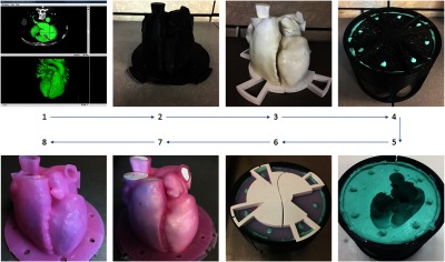
Workflow showing the manufacturing of a patient-specific cardiac model. Step 1 displaying the initial blood pool segmentation. Step 2 is the thickened 3-D printed blood pool model. Step 3 is the 3-D printed blood pool model. Step 4 is the silicone mold generation using the 3-D printed container. Step 5 is the completed silicone mold. Step 6 is the silicone mold with the blood pool model aligned within. Step 7 is the completed silicone model with the blood pool model inside. Step 8 is the completed hollow silicone model.
2.3. Computer-Aided Design Stereolithography Manipulations
Using the software MeshLab,26 the STL models were imported and corrected. To manage the size of the models, decimation was used to reduce the overall number of triangles, without affecting the overall geometry. The model was then smoothed using a Taubin Filter27 to remove any artifacts generated during the segmentation, decimation, and scanning processes. The corrected models were then imported into the CAD software, SpaceClaim,28 which allows an STL model to be edited. Using SpaceClaim, the model was cut crossing the left and right ventricles to allow for the model to be integrated into the heart phantom. Next, the model was uniformly offset by 3 mm to generate an artificial myocardium. Finally, a flange was added to the patient-specific model, allowing it to be connected to the phantom container in the correct orientation. The time required for CAD manipulations was .
2.4. 3-D Printing Technologies
The modified STL models were then printed using fused deposition modeling on the Ultimaker 3 Extended 3-D printer.29 Models were printed using Cura version 2.5.0. The settings used for the prints included a layer height of 0.1 mm, a shell thickness of 0.8 mm, a fill for the bottom/top thickness of 0.6 mm, an infill density of 20%, and an extruder nozzle diameter of 0.4 mm, with support material used everywhere as required. The models were printed using polylactic acid (PLA) filament. The settings chosen for these prints were used to produce high-quality parts and replicate the patient’s anatomy as closely as possible while using a simple, inexpensive printer. Printing time for the components: outer cardiac model (Fig. 1: step 2), inner cardiac model (Fig. 1: step 3), flange and mold container, was .
2.5. Postprocessing
After printing, the models were postprocessed to remove any artifacts generated during the 3-D printing process. The first step was to remove any support material used during the printing process. Next, the models were sanded using low grit sandpaper to remove any small artifacts, such as stepping in between layers and any material left connected after breaking away the support structure. The models were then coated with Smooth-On XTC-3D® to assist in sealing the components and remove any remaining stepping artifacts between layers. After allowing the XTC-3D® to cure, the models were then sanded again to remove any final artifacts and to ensure an even coating of the sealant. Postprocessing of the 3-D printed parts was .
2.6. Molding
Due to the complex nature of cardiac anatomy, we have chosen to use a flexible silicone mold (Fig. 1: step 4) that allows for the manufacture of complex organic shapes. To build the flexible mold, a custom housing was 3-D printed. The rigid model representing the 3-mm offset from the blood pool segmentation was aligned within the mold housing and used as a mold positive. The mold was created by pouring Smooth-On Mold Star® 16 Fast silicone around the 3-D printed model into the 3-D printed mold housing. The housing was designed to have alignment pins that ensured the blood pool model and 3 mm offset model could be aligned such that the production of all subsequent models would produce consistent results. By designing a custom container for molding, we produced a flexible, single part mold that can generate the patient-specific cardiac model.
Following curing of the silicone mold, the 3-D printed models were removed, resulting in the negative of the outer cardiac wall (Fig. 1: step 5). The 3-D printed models representing the internal blood pool were then inserted into the mold, utilizing the alignment features to ensure the models were in the correct orientation (Fig. 1: step 6). Tissue mimicking materials, either silicone or polyvinyl alcohol cryogel (PVA-C), were used to make the hollow patient-specific model. Building on previous work from our lab, the silicone material used was Smooth-On Ecoflex® 00-30, chosen for its high flexibility and durability. Ecoflex® 00-30 has a density of , a tensile strength of 1.38 MPa, and an elongation at break of 900%.30 To produce a part with optimal echogenicity, the two-part silicone is mixed and degassed in a degassing chamber to remove any air that has been mixed into the silicone. When all the trapped air bubbles have been removed, the material is poured into the mold and left to cure for 8 h.
To produce a PVA-C model, the PVA mixture was created by dissolving 10% by weight, Aldrich Chemistry PVA crystals in hot (95°C) water. When the mixture has cooled, it was poured into the mold and the material was allowed to sit, so that trapped air bubbles rise to the surface and escape. The mold was then placed into an environment chamber (Test Equity 1000) in which it goes through three freeze-thaw cycles. Each cycle ramped from room temperature to and held for 24 h, after which the chamber gradually warmed to room temperature and held for 12 h. As this cycle was repeated, the liquid PVA-C mixture gradually changed into a flexible material, which exhibits a speed of sound and attenuation coefficient like that of cardiac tissue while maintaining a realistic flexibility.31
The final step in the production of both a silicone and PVA-C model was to remove it from the mold (Fig. 1: step 7). Given the flexibility of both silicone and PVA-C, the rigid 3-D printed models can be removed by stretching the flexible model and pulling the rigid model out. With the 3-D printed models of the internal blood pool removed from the model, we are left with a hollow patient-specific cardiac model (Fig. 1: step 8). The total time for a silicone model to be produced is week and for a PVA-C version, weeks.
2.7. Valve Manufacturing
Given the thinness of mitral and tricuspid valve leaflet, 3 to 5 mm,32 and the high degree of rapid motion (), our clinical CT scan was unable to clearly identify valves. The valves act as important landmarks and guides during beating heart interventions, so it is important that the models still contain valves to aid clinicians in interpreting the patient’s anatomy and for guiding the catheter within the model. To overcome this, we have developed a methodology for creating both patient-specific33 and generalized valve models. As we did not have a TEE scan from this patient, a different patient’s TEE scan, acquired in systole, was used to generate a mitral valve model, with the only modification being scaling of the computational model to fit the other patient. In addition, we have also developed a generalized tricuspid valve using the same manufacturing methods that can be added to the patient-specific cardiac model.
These valves are constructed using a 3-D printed mold made of PLA (Fig. 2: step 1). Silicone is painted onto the mold and allowed to cure. The silicone chosen for these models is Smooth-On Ecoflex® 00-30, as it is highly durable and flexible, resulting in a realistic valve movement within a phantom. Chordae are simulated within the valve by including braided nylon strings at key locations during the molding process within the model. Once inside the phantom, the nylon strings are connected to the corresponding access point using a silicone plug that simulates the connection of the chordae to the heart wall and maintains the valve’s shape. Following curing of the silicone, the valve model can be removed from the mold by peeling the silicone off the 3-D printed part (Fig. 2: step 2). The valve flange was covered using Smooth-On Sil-Poxy to properly adhere the mitral and tricuspid valves to the patient-specific model. This is a single cure bonding silicone (Fig. 2: steps 3 and 4) that acts as an adhesive agent, bonding the silicone valves and heart models together. The final 3-D anatomical model contains the patient-specific cardiac wall, a patient-specific mitral valve, and a generalized tricuspid valve.
Fig. 2.

Workflow showing the manufacturing of a patient-specific valve model. Step 1 is the 3-D printed mitral valve model. Step 2 is the completed silicone mitral valve model. Step 3 is the silicone mitral valve adhered to the silicone heart model. Step 4 displayed both the mitral and tricuspid valves adhered to the heart model.
2.8. Phantom Design
The phantom container was designed to accommodate the 3-D anatomical model and allow for the simulation of minimally invasive cardiac procedures. For this to be accomplished, clinicians were consulted to develop the design specifications that would ensure the phantom would perform as required. This included tool access at common access points large enough for a variety of catheters and compatibility with TEE ultrasound, CT, and fluoroscopy to visualize tools and anatomical features within the model. To accomplish this, both the phantom chamber and the model were constructed using materials that would not cause unrealistic artifacts in ultrasound and x-ray imaging. The phantom is designed as a water-filled container, allowing for ultrasound as well as the ability to simulate fluid dynamics within the chambers and across the valves.
2.9. Phantom Materials and Shape
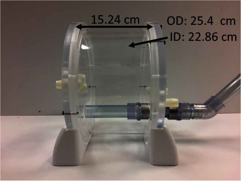
For the phantom to be compatible with the imaging modalities used throughout a minimally invasive cardiac procedure, it was designed to contain no metal and to use components that do not distort imaging of the 3-D anatomical model within the chamber. The outer cylindrical chamber and walls of the phantom were constructed using acrylic, as this material does not distort the 3-D anatomical model within the chamber. The stand used was 3-D printed using the Ultimaker 3 using PLA material, and all the fasteners used were nylon or silicone. The overall length of the phantom is 15.24 cm, the cylindrical container has an outer diameter of 25.4 cm, and an inner diameter of 22.86 cm, as shown in Fig. 3.
Fig. 3.
Cardiac phantom container dimensions.
2.10. Access Points
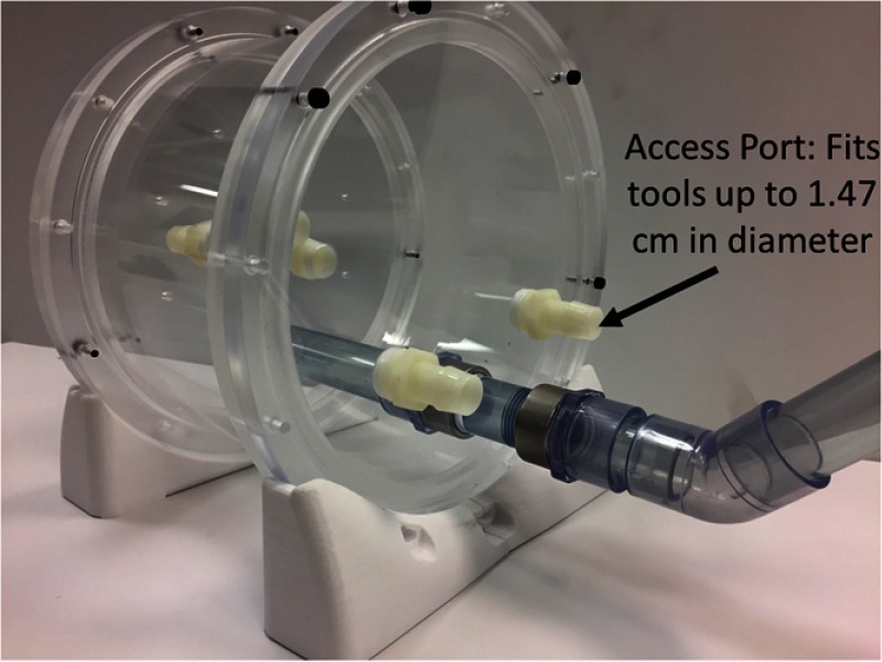
The phantom container has five access points into the cardiac model at strategic locations. The access points are located at the inferior and superior vena cava, right ventricle, left ventricle, and in line with the aortic arch. These locations can be used to simulate catheter insertion locations for cardiac procedures or as locations for flow to be added to the phantom. Each access point is capable of accommodating tools up to 1.47 cm in diameter and will fit all catheters up to and including 40 French. The phantom container also has access for a TEE probe to be inserted into a simulated esophagus. Within the phantom, there are two options for the esophagus, a rigid acrylic tube, or a flexible PVA-C model, which constrain the movement of the probe within the phantom and to provide realistic material properties to the esophagus (Fig. 4).
Fig. 4.
Cardiac phantom container access points.
2.11. Model Accommodation
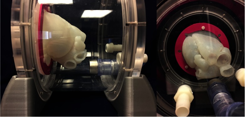
The 3-D anatomical model is held within the phantom using a series of eight nylon screws, each of which connects the flange of the model to the wall of the phantom, securing it in place. A 3-D printed interfacing component applies uniform pressure to the model flange, helping to maintain the position of the cardiac model throughout a simulated procedure (Fig. 5). The model itself is contained entirely within the phantom container. In use, the phantom is filled with water, which helps to prevent the model from sagging due to gravity, and maintains the anatomical position.
Fig. 5.
Phantom with the 3-D anatomical model and flange seal (pink) holding it in place.
3. Validation
3.1. Validation of the Model
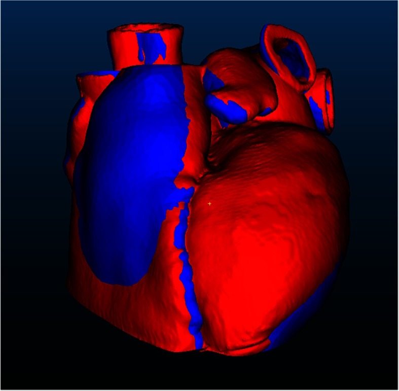
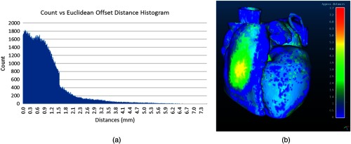
Validation of the final patient-specific model was performed using a CT scanner, a Medtronic O-Arm® with a voxel size of . The model was scanned within the phantom container, positioned as it would be for a simulated intervention. While not neutrally buoyant in water, the material properties of silicone were sufficiently stiff to keep the model from sagging noticeably and held it in a stable position. The completed high-resolution 3-D CT scan was then segmented and used to create a geometric model, which was subsequently exported as an STL file that was employed to compare the final model to the original patient data. Using the software program CloudCompare,34 the final model was registered to the original patient STL model using the original iterative closest point algorithm,35 as shown in Fig. 6, where the blue model is the original segmentation from patient data and the red is the scanned silicone model. The registered models were then used to measure absolute distance between point cloud datasets (Fig. 7) to determine the accuracy of the physical models.
Fig. 6.
Registered models. The blue model is the original segmentation from patient data and the red model is the scanned silicone model.
Fig. 7.
(a) The histogram shows the results of the Euclidean offset distance. (b) The results of the Euclidean distance comparison between the silicone and original patient model.
3.2. Validation by Simulating a Mitral Valve Repair
The phantom was validated to determine its ability to realistically display anatomical features and surgical instruments within the phantom. For the phantom to effectively simulate a cardiac procedure, the imaging parameters of the model, and the visualization of tools under fluoroscopy and ultrasound within the phantom need to be realistic. This was verified by replicating a MitraClip® procedure and positioning the tool at important landmarks.
The MitraClip® procedure is performed to repair a flailing mitral valve leaflet and mitigate mitral regurgitation. A catheter containing the Mitraclip® tool is inserted into the femoral vein and guided using fluoroscopy imaging through the venous system and into the heart. Once inside the patient’s heart, TEE ultrasound is used in addition to fluoroscopy to guide the tool and interpret anatomy. The device enters the right atrium within the heart through the inferior vena cava. The catheter then must pass through the atrial septal wall and enter the left atrium. The accuracy of the septal puncture is critical, as the catheter must have enough room within the left atrium to properly align the tool with the valve. Once inside the left atrium, the tool is navigated to the flailing mitral leaflet, where the tool is used to grasp and deploy the device. Once complete, the patient’s mitral regurgitation should be reduced.
We chose the MitraClip® procedure due to its reliance on both ultrasound and fluoroscopy when guiding the percutaneous tools within the patient. The procedure was simulated using a Medtronic O-Arm® scanner for both CT and fluoroscopy, and in addition, the model was viewed under TEE ultrasound guidance using the Phillips iE33 Ultrasound machine. Images were acquired by an experienced anesthetist, who simulated the standard views used during a MitraClip® procedure. The tool was manipulated by an Abbott Canada MitraClip® representative, who is experienced using and positioning the tool.
The simulation of the MitraClip® procedure was performed using the cardiac phantom in a static environment. The Mitraclip® device was navigated within the phantom, as would be performed in a normal procedure, where it entered through the inferior vena cava into the right atrium, passed through the atrial septal wall and was navigated to the mitral valve. Throughout the simulation, the tool was navigated under image guidance and positioned at the septal wall and within the left atrium of the model, simulating the critical locations of the procedure as deemed by our clinicians. In total, the duration of the simulation lasted 2 h, during which the tool was navigated within the phantom and the images were acquired. The resulting images were evaluated qualitatively and compared to patient images published in the Abbott Canada MitraClip® training guide.
4. Results
4.1. Results of the Model
To verify the accuracy of the cardiac model, the two point-cloud models were compared using Euclidean offset distance. For this single patient dataset trial, when comparing the point cloud of the physical silicone model to the original dataset, we observe a maximum deviation of 7.7 mm, between the two surfaces, an average of 0.98 mm, and a standard deviation of 0.91 mm. The full histogram of the results is shown in Fig. 7(a), and a color map of the absolute distances between the scanned model and the original patient is displayed in Fig. 7(b).
4.2. Results of Simulating a Mitral Valve Repair
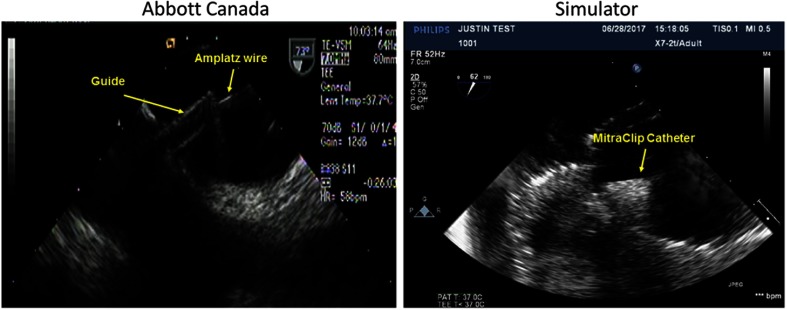
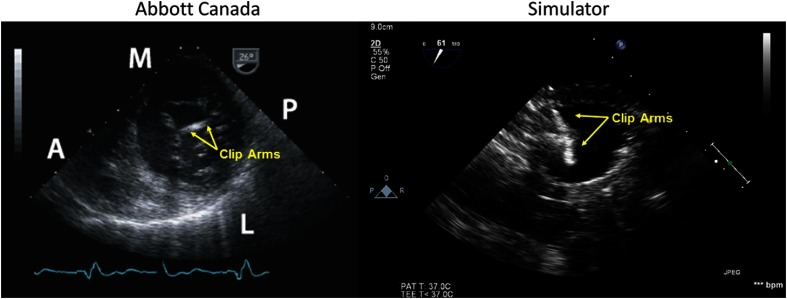
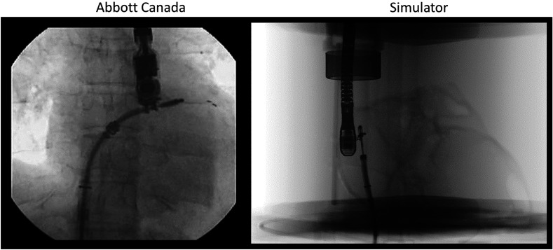
When comparing the ultrasound and fluoroscopy images of the cardiac model within the simulator to the training images from Abbott Canada, there are some key points worth noting. The tool is clearly visible within the cardiac model at the key points evaluated, across the septal wall, and within the left atrium, ensuring that it is visible during a simulated procedure and that it provides realistic visual feedback for the clinician.
As the tool is maneuvered through the femoral vein to the inferior vena cava and into the right atrium, the clinician begins to track the tool using ultrasound guidance. Upon entry into the right atrium, the tool is aligned with the fossa ovalis to puncture the atrial septal wall. In a MitraClip® procedure, the tool must puncture the septal wall at a targeted position to allow for sufficient space within the left atrium to bend the catheter and align the tool head with the mitral valve.
In a study from 2011, the average duration of a MitraClip® procedure was .36 This variation is significant since for cases of complex anatomy, the septal puncture can account for up to 50% of the surgery duration, much of which is accomplished under fluoroscopic guidance. The total time required and the variance are also indicators of the cognitive demand placed on clinicians to accurately interpret ultrasound and fluoroscopic images, and translate these data into the correct physical manipulation of the tool. It is then imperative that the tool and the fossa ovalis can be identified under ultrasound guidance at this stage to accurately simulate the puncture and crossing of the fossa ovalis.
The images were acquired without the use of a septal wall puncture catheter, the MitraClip® introducer, or sheath, resulting in some disparity in the images at the septal wall. Although the introducer and sheath are not present, the MitraClip® tool head and catheter are visible under image guidance across the septal wall (Fig. 8). This is useful for cases of septal wall puncture since a clinician would be able to both identify the fossa ovalis and a catheter under image guidance to perform a simulated septal puncture. The tool was visible under ultrasound guidance within the phantom on both sides of the septal wall. This results in sufficiently realistic imaging and catheter guidance within the phantom for replication of a septal puncture from an imaging perspective.
Fig. 8.
Comparison of MitraClip® under ultrasound guidance crossing septal wall (silicone phantom).
Once across the septal wall, the clinician maneuvers the tool to position it in line with the valve. To accomplish this, they must be able to see the tool within the left atrium and identify the location of the tool’s graspers, enabling them to align the tool with the flailing leaflet. When evaluating the phantom, the tool was placed within the left atrium and the graspers of the tool were opened. Both arms of the MitraClip® are visible and identifiable under ultrasound (Fig. 9) and fluoroscopy imaging (Fig. 10).
Fig. 9.
Comparison of MitraClip® under ultrasound guidance in the left atrium (silicone phantom).
Fig. 10.
Comparison of MitraClip® under fluoroscopy guidance in the left atrium (silicone phantom).
Because the MitraClip® instrument is single use (and only one was available), the procedure ended just prior to deploying the clip onto the valve. The results of this study demonstrate the ability of this methodology to accurately replicate a patient’s cardiac anatomy with a high degree of accuracy and to simulate a minimally invasive cardiac procedure under image guidance. According to the clinicians involved, the surgical phantom creates a realistic training environment for the MitraClip procedure. Using this methodology, a 3-D anatomical cardiac model can be generated as a tool for preprocedure surgical planning, which can also act as an accurate static replica of what the clinician could expect to see during the surgery. It also demonstrates the ability to replicate the stages of the procedure with the greatest cognitive demand (traversing the septal wall). According to our clinical collaborators, the phantom provides the ability for them to train the motor patterns required to manipulate the tool and perform the image guidance in an anatomically correct environment.
5. Discussion
We have demonstrated a methodology to accurately build 3-D anatomical models of cardiac anatomy that can be used within a surgical phantom for simulation of minimally invasive cardiac procedures. The cardiac model recreates important anatomical features as seen in the patient’s CT scan in a physical, flexible form. These models can be made from tissue mimicking materials, such as PVA-C and silicone, allowing the user to control the material properties of the model by selecting different silicone brands and products or varying the number of freeze-thaw cycles for PVA-C.31 In the simulated procedure utilizing a MitraClip® tool, we have shown the ability to display anatomical features that are compatible with ultrasound and fluoroscopy imaging using a silicone cardiac model. This allows the phantom to be used as a simulator with 3-D anatomical models, a training tool for clinicians, and as a means for validating new image-guided techniques.
Silicone was chosen over PVA-C for the simulation as valves can be adhered to the silicone model, and silicone remains stable in both air and water, whereas the PVA-C model will shrink over if not maintained in a proper hydrated state, making the size of the model unpredictable. When both models are imaged using fluoroscopy, silicone is more easily identified than normal cardiac tissue, whereas PVA-C has little contrast with respect to water. Without other anatomy, such as the ribs to act as spatial identifiers, the PVA-C model becomes very difficult to use under fluoroscopic guidance. While silicone is more easily seen than normal cardiac tissue, this characteristic could be a beneficial characteristic for new trainees.
3-D anatomical models made from tissue mimicking materials could make it possible for clinicians to gain insight into areas of concern due to diseased or complicated anatomy, for example, by selecting the optimal size for a left atrial appendage closure device or assessing septal puncture locations for MitraClip® delivery prior to a surgery. Clinicians have the ability to fully examine, plan, and test fit devices within the models prior to performing a procedure. Furthermore, employing these models in combination with a surgical phantom allows clinicians to simulate and practice the procedure. Used as a surgical planning tool, these models may allow for a more informed surgical plan, which could lead to shorter surgical times and better patient outcomes.
The model was scanned and validated within the chamber to evaluate the efficacy of the phantom to accurately support and maintain the model’s functionality during use. To fully demonstrate the accuracy of the manufactured model, it could be scanned with the 3-D printed blood pool inside the flexible silicone. While this would ensure that the model was being supported as effectively as possible, it would not demonstrate the accuracy of the model within the phantom. We report a maximum error of 7.7 mm; however, this offset distance is primarily found in areas, where the model was sagging, since the model was not uniformly supported during the CT scan.
The use of surgical phantoms in replicating minimally invasive cardiac procedures is a developing field that aims to provide the opportunity to recreate the experience of a minimally invasive procedure outside of the operating room. This ability will allow clinicians to learn or maintain their skill level to work on a phantom and hone their skills without any risk to patients or the need to employ animal models. This approach also allows for a measure of quality control between hospitals, where the number of procedures performed may be drastically different. There is evidence that the frequency with which a clinician performs a procedure can directly impact the outcome for a patient.37 Allowing clinicians to train using a realistic surgical phantom may help to bridge the skill gap between institutions and help to provide better and more consistent care for patients.
As surgical phantoms are increasingly used as simulators and training tools, the number of patient-specific models will increase, resulting in a range of models with varying anatomy and pathologies. Ultimately, surgical phantoms could provide clinicians with a training environment that allows them to experience complex surgical scenarios with no risk to patients.
In our work, the model container was made to accommodate a wide range of cardiac sizes, allowing it to be compatible with a range of pathologies and models. Thus, to prepare a model for simulation, training, or validation, the limiting factor is the manufacturing time of the silicone or PVA-C model. Using the current workflow, the time required to manufacture the 3-D anatomical cardiac model requires upward of 2 weeks from the time we receive the patient’s scan. For surgical planning, the current workflow of 2 weeks is within the standard typical time frame between a patient’s scan and the surgery. Using the current workflow, for procedures where the time from the initial scan and the procedure is less than 2 weeks, using this methodology would not be feasible. Although labor intensive, developing these models for patients with complex pathologies may provide clinicians with the information they need to reduce the risk of potential complications when performing the procedure. For clinical training and validation, the time required to construct a model is less critical, and the 2 weeks required is acceptable. Using the current workflow, multiple different models can be created simultaneously, and once a mold has been completed, models can be built with as little as an additional hour of labor.
Future integrations with tool tracking and augmented reality could provide clinicians with feedback regarding the tool’s location within the phantom and the optimal tool path to follow. Also with tool tracking, the clinician’s tool path, puncture location, or device placement could be evaluated against the ideal location. Providing this feedback to the user would allow them to learn and improve their skills. Other future work includes the adaptation of the static cardiac model to a dynamic one. The current phantom is designed to allow for flow to be added to the system using a reciprocating pump, which connects at key locations within the model creating realistic mitral and tricuspid valve motion. The valves within the system currently act as spatial identifiers for clinicians. As the valves move, they become more easily located under ultrasound guidance and aid clinicians in interpreting anatomical features within the heart.
In evaluating our surgical phantom in comparison to the state–of-the-art in the literature, there are few key distinctions that can be made. Currently, there are a number of groups developing very accurate preoperative surgical models using 3-D printing.38,39 These models allow clinicians to evaluate anatomically correct models, which can be imaged using fluoroscopy and CT. The limitation of building models using 3-D printing is the lack of control on the material properties of the final product. By employing silicone or PVA-C for the molding of our anatomical model, we were able to produce an accurate model, which was not only suitable for evaluation of a patient’s anatomy but also appeared anatomically correct when viewed with both fluoroscopy and ultrasound. This is a defining characteristic of our approach since TEE ultrasound is a commonly used imaging technique for many cardiac interventions. In addition, previous work has been reported by our lab and others to develop flexible anatomical models that can both be used to visualize anatomical features and interact with the models.24,40 These models have been anatomical representations of just the left and right atria and did not represent valves or ventricular anatomy. In our surgical phantom, we were not only able to accurately represent a patient’s cardiac anatomy, including the atria, septal wall, the mitral and tricuspid valves, in addition to a partial left and right ventricle, but also we were able to incorporate the model into a surgical phantom that could be used for surgical simulation and training. Performing simulations using the 3-D anatomical model not only increases the realism for the user but also increases the phantoms potential as a training simulator, ultimately differentiating the phantom from previous work that used generalized models for simulation.41 The completeness of the 3-D anatomical model also provides the potential for other cardiac inventions, such as left atrial appendage closure, ventricular septal defect closure, atrial septal defect closure, or atrial ablation or be simulated.
Despite the advantages previously outlined, there are limitations to this work. One drawback is the time required to build these flexible models. When compared to directly 3-D printing the models, the added manufacturing steps of building molds, molding, and the curing of materials increase the total time of production. In addition, there are accuracy drawbacks of molding when compared to 3-D printing. Because of the flexible nature of molding, error on the part of the individual building the model, and additional 3-D printing steps that can cumulatively add error, direct 3-D printing can produce more accurate models than molding.
6. Conclusion
We have developed a methodology for building 3-D anatomical cardiac models from preoperative CT scans and incorporating them into a cardiac phantom. Using this approach, we have demonstrated the ability to simulate a minimally invasive cardiac procedure by performing a MitraClip® intervention using a 3-D anatomical cardiac model. The phantom is capable of visualizing surgical instruments within the cardiac model, in addition to providing a simulation environment sufficient to train for minimally invasive procedures and surgical planning. It is our hope that this cardiac simulation system will provide new clinicians with the opportunity to train using surgical tools in a realistic surgical environment, with both basic and complex models. In addition, the simulator can be used by researchers to test and validate new image-guided techniques and augmented reality systems. Finally, we hope to see the simulator used in preprocedure planning for cases, where a patient would not be eligible to receive treatment due to their complex anatomy or pathology.
Biography
Biographies for the authors are not available.
Disclosures
No conflicts of interest, financial or otherwise, are declared by the authors.
References
- 1.Mozaffarian D., et al. , “Heart disease and stroke statistics-2015 update: a report from the American Heart Association,” Circulation 131(4), e29–e322 (2015).https://doi.org/10.1161/CIR.0000000000000152 [DOI] [PubMed] [Google Scholar]
- 2.Shafiee A., Atala A., “Printing technologies for medical applications,” Trends Mol. Med. 22(3), 254–265 (2016).https://doi.org/10.1016/j.molmed.2016.01.003 [DOI] [PubMed] [Google Scholar]
- 3.Martelli N., et al. , “Advantages and disadvantages of 3-dimensional printing in surgery: a systematic review,” Surgery 159(6), 1485–1500 (2016).https://doi.org/10.1016/j.surg.2015.12.017 [DOI] [PubMed] [Google Scholar]
- 4.Chen S., et al. , “3-D finite element modelling of facial soft tissue and preliminary application in orthodontics,” Comput. Methods Biomech. Biomed. Eng. 15(3), 255–261 (2012).https://doi.org/10.1080/10255842.2010.522188 [DOI] [PubMed] [Google Scholar]
- 5.Jernigan S. R., et al. , “Finite element modeling of the left atrium to facilitate the design of an endoscopic atrial retractor,” J. Biomech. Eng. 129(6), 825–837 (2007).https://doi.org/10.1115/1.2801650 [DOI] [PubMed] [Google Scholar]
- 6.Cantinotti M., Valverde I., Kutty S., “Three-dimensional printed models in congenital heart disease,” Int. J. Cardiovasc. Imaging 33(1), 137–144 (2016).https://doi.org/10.1007/s10554-016-0981-2 [DOI] [PubMed] [Google Scholar]
- 7.Giannopoulos A. A., et al. , “Cardiothoracic applications of 3-dimensional Printing,” J. Thorac. Imaging 31(5), 253–272 (2016).https://doi.org/10.1097/RTI.0000000000000217 [DOI] [PMC free article] [PubMed] [Google Scholar]
- 8.Giannopoulos A. A., et al. , “Applications of 3D printing in cardiovascular diseases,” Nat. Rev. Cardiol. 13(12), 701–718 (2016).https://doi.org/10.1038/nrcardio.2016.170 [DOI] [PubMed] [Google Scholar]
- 9.Sturla F., et al. , “Is it possible to assess the best mitral valve repair in the individual patient? Preliminary results of a finite element study from magnetic resonance imaging data,” J. Thorac. Cardiovasc. Surg. 148(3), 1025–1034; discussion 1034 (2014).https://doi.org/10.1016/j.jtcvs.2014.05.071 [DOI] [PubMed] [Google Scholar]
- 10.Stevanella M., et al. , “Mitral valve patient-specific finite element modeling from cardiac MRI: application to an annuloplasty procedure,” Cardiovasc. Eng. Technol. 2(2), 66–76 (2011).https://doi.org/10.1007/s13239-010-0032-4 [Google Scholar]
- 11.Pellegrino P. L., et al. , “Left atrial appendage closure guided by 3D printed cardiac reconstruction: emerging directions and future trends,” J. Cardiovasc. Electrophysiol. 27(6), 768–771 (2016).https://doi.org/10.1111/jce.12960 [DOI] [PubMed] [Google Scholar]
- 12.Sodian R., et al. , “Stereolithographic models for surgical planning in congenital heart surgery,” Ann. Thorac. Surg. 83(5), 1854–1857 (2007).https://doi.org/10.1016/j.athoracsur.2006.12.004 [DOI] [PubMed] [Google Scholar]
- 13.Schmauss D., et al. , “Three-dimensional printing of models for preoperative planning and simulation of transcatheter valve replacement,” Ann. Thorac. Surg. 93(2), e31–e33 (2012).https://doi.org/10.1016/j.athoracsur.2011.09.031 [DOI] [PubMed] [Google Scholar]
- 14.Schmauss D., et al. , “Three-dimensional printing in cardiac surgery and interventional cardiology: a single-centre experience,” Eur. J. Cardiothorac. Surg. 47(6), 1044–1052 (2015).https://doi.org/10.1093/ejcts/ezu310 [DOI] [PubMed] [Google Scholar]
- 15.Vukicevic M., et al. , “3D printed modeling of the mitral valve for catheter-based structural interventions,” Ann. Biomed. Eng. 45(2), 508–519 (2016).https://doi.org/10.1007/s10439-016-1676-5 [DOI] [PubMed] [Google Scholar]
- 16.Sardari Nia P., et al. , “Preoperative planning with three-dimensional reconstruction of patient’s anatomy, rapid prototyping and simulation for endoscopic mitral valve repair,” Interact. Cardiovasc. Thorac. Surg. 24(2), 163–168 (2016).https://doi.org/10.1093/icvts/ivw308 [DOI] [PubMed] [Google Scholar]
- 17.McGaghie W. C., et al. , “Does simulation-based medical education with deliberate practice yield better results than traditional clinical education? A meta-analytic comparative review of the evidence,” Acad. Med. J. Assoc. Am. Med. Coll. 86(6), 706–711 (2011).https://doi.org/10.1097/ACM.0b013e318217e119 [DOI] [PMC free article] [PubMed] [Google Scholar]
- 18.Kneebone R., “Simulation in surgical training: educational issues and practical implications,” Med. Educ. 37(3), 267–277 (2003).https://doi.org/10.1046/j.1365-2923.2003.01440.x [DOI] [PubMed] [Google Scholar]
- 19.Okuda Y., Quinones J., “The use of simulation in the education of emergency care providers for cardiac emergencies,” Int. J. Emerg. Med. 1(2), 73–77 (2008).https://doi.org/10.1007/s12245-008-0034-2 [DOI] [PMC free article] [PubMed] [Google Scholar]
- 20.Li F. P., et al. , “A mitral annulus tracking approach for navigation of off-pump beating heart mitral valve repair,” Med. Phys. 42(1), 456–468 (2015).https://doi.org/10.1118/1.4904022 [DOI] [PubMed] [Google Scholar]
- 21.McLeod A. J., Moore J. T., Peters T. M., “Beating heart mitral valve repair with integrated ultrasound imaging,” Proc. SPIE 9415, 941504 (2015).https://doi.org/10.1117/12.2082414 [Google Scholar]
- 22.McLeod A. J., et al. , “Phantom study of an ultrasound guidance system for transcatheter aortic valve implantation,” Comput. Med. Imaging Graph 50, 24–30 (2014).https://doi.org/10.1016/j.compmedimag.2014.12.001 [DOI] [PubMed] [Google Scholar]
- 23.Mason W. T. M., Strike P. W., “Short CommunicationSee one, do one, teach one—is this still how it works? A comparison of the medical and nursing professions in the teaching of practical procedures,” Med. Teach. 25(6), 664–666 (2003).https://doi.org/10.1080/01421590310001605705 [DOI] [PubMed] [Google Scholar]
- 24.Laing J., et al. , “Patient-specific atrium models for training and pre-procedure surgical planning,” Proc. SPIE 10135, 101351A (2017).https://doi.org/10.1117/12.2249693 [Google Scholar]
- 25.Fedorov A., et al. , “3D slicer as an image computing platform for the quantitative imaging network,” Magn. Reson. Imaging 30(9), 1323–1341 (2012).https://doi.org/10.1016/j.mri.2012.05.001 [DOI] [PMC free article] [PubMed] [Google Scholar]
- 26.Cignoni P., et al. , MeshLab: An Open-Source Mesh Processing Tool, Eurographics Association, Italy: (2008). [Google Scholar]
- 27.Taubin G., “A signal processing approach to fair surface design,” in Proc. of the 22nd Annual Conf. on Computer Graphics and Interactive Techniques, pp. 351–358, ACM, New York, NY: (1995). [Google Scholar]
- 28.“3D modeling software for engineering SpaceClaim,” http://www.spaceclaim.com/en/default.aspx (6 May 2017).
- 29.“Ultimaker 3 | Ultimaker,” https://ultimaker.com/en/products/ultimaker-3 (7 June 2017).
- 30.Smooth- Inc., “Ecoflex® 00-30 Product Information,” https://www.smooth-on.com/products/ecoflex-00-30/ (4 January 2018).
- 31.Surry K. J. M., et al. , “Poly(vinyl alcohol) cryogel phantoms for use in ultrasound and MR imaging,” Phys. Med. Biol. 49(24), 5529–5546 (2004).https://doi.org/10.1088/0031-9155/49/24/009 [DOI] [PubMed] [Google Scholar]
- 32.Omran A. S., Arifi A. A., Mohamed A. A., “Echocardiography of the mitral valve,” J. Saudi Heart Assoc. 22(3), 165–170 (2010).https://doi.org/10.1016/j.jsha.2010.04.001 [DOI] [PMC free article] [PubMed] [Google Scholar]
- 33.Ginty O., et al. , “Patient-specific indirectly 3D printed mitral valves for pre-operative surgical modelling,” Proc. SPIE 10135, 1013517 (2017).https://doi.org/10.1117/12.2255567 [Google Scholar]
- 34.Girardeau-Montaut D., “CloudCompare—open source project,” [CloudCompare], GPL Software, http://www.cloudcompare.org/ (10 July 2017).
- 35.Besl P. J., McKay H. D., “A method for registration of 3-D shapes,” IEEE Trans. Pattern Anal. Mach. Intell. 14(2), 239–256 (1992).https://doi.org/10.1109/34.121791 [Google Scholar]
- 36.Auricchio A., et al. , “Correction of mitral regurgitation in nonresponders to cardiac resynchronization therapy by MitraClip improves symptoms and promotes reverse remodeling,” J. Am. Coll. Cardiol. 58(21), 2183–2189 (2011).https://doi.org/10.1016/j.jacc.2011.06.061 [DOI] [PubMed] [Google Scholar]
- 37.Birkmeyer J. D., et al. , “Surgeon volume and operative mortality in the United States,” N. Engl. J. Med. 349(22), 2117–2127 (2003).https://doi.org/10.1056/NEJMsa035205 [DOI] [PubMed] [Google Scholar]
- 38.Rettmann M. E., et al. , “Quantitative modeling of the accuracy in registering preoperative patient-specific anatomic models into left atrial cardiac ablation procedures,” Med. Phys. 41(2), 021909 (2014).https://doi.org/10.1118/1.4861712 [DOI] [PMC free article] [PubMed] [Google Scholar]
- 39.Izzo R. L., et al. , “3D printed cardiac phantom for procedural planning of a transcatheter native mitral valve replacement,” Proc. SPIE 9789, 978908 (2016).https://doi.org/10.1117/12.2216952 [DOI] [PMC free article] [PubMed] [Google Scholar]
- 40.Morais P., et al. , “Development of a patient-specific atrial phantom model for planning and training of inter-atrial interventions,” Med. Phys. 44(11), 5638–5649 (2017).https://doi.org/10.1002/mp.2017.44.issue-11 [DOI] [PubMed] [Google Scholar]
- 41.Lesniak-Plewinska B., et al. , “A dual-chamber, thick-walled cardiac phantom for use in cardiac motion and deformation imaging by ultrasound,” Ultrasound Med. Biol. 36(7), 1145–1156 (2010).https://doi.org/10.1016/j.ultrasmedbio.2010.04.008 [DOI] [PubMed] [Google Scholar]


