Abstract
We introduce a family of fast ordered upwind methods for approximating solutions to a wide class of static Hamilton–Jacobi equations with Dirichlet boundary conditions. Standard techniques often rely on iteration to converge to the solution of a discretized version of the partial differential equation. Our fast methods avoid iteration through a careful use of information about the characteristic directions of the underlying partial differential equation. These techniques are of complexity O(M log M), where M is the total number of points in the domain. We consider anisotropic test problems in optimal control, seismology, and paths on surfaces.
Introduction
Equations and Discretizations.
Consider the first-order nonlinear partial differential equation (PDE)†
 |
1 |
with the boundary condition u(x) = q(x) given on ∂Ω. Smoothness in boundary data does not guarantee that a smooth solution exists. For the class of Hamilton–Jacobi equations, weak solutions can be formally introduced; a unique viscosity solution can be defined by using conditions on smooth test functions (1, 2).
In this paper, we develop fast methods for approximating the solution to equations of this form. Start with a mesh X covering the domain Ω. Let Ui be the numerical solution value at the mesh point xi ∈ X. Denote the set of mesh points adjacent to xi as N(xi) and the set of values adjacent to Ui as NU(xi) = {Uj|xj ∈ N(xi)}. Let H̄ be a consistent discretization of H, such that one can write
 |
2 |
If M is the total number of mesh points, then one needs to solve M coupled nonlinear equations simultaneously. One approach is to solve this nonlinear system iteratively. For example, iterative techniques for some equations arising in control theoretic problems are given in refs. 3, 11, and 23; an iterative technique for the Eikonal equation based on an upwind finite difference formulation is given in ref. 4.
Our goal in this work is to introduce a set of “single-pass” algorithms. By this term, we mean that each Ui is recalculated at most r times, where r depends only on Eq. 1 and the mesh structure but not on the diameter of the mesh.
Characteristics and Ordering Updates.
To construct single-pass algorithms with efficient update orderings, we utilize the fact that the value of u(x) for the first-order PDE depends only on the value of u along the characteristic(s) passing through the point x. If xi1, xi2 ∈ N(xi) are such that the characteristic for the mesh point xi lies in the simplex xixi1xi2, then it is useful to consider an upwind discretization of the PDE:
 |
3 |
This reduces the coupling in the system: Ui depends only on Ui1 and Ui2 and not on all of the NU(xi). A recursive construction allows one to build the entire dependency graph for xi.
If two or more characteristics collide at a point x, the solution loses smoothness. The entropy condition does not allow characteristics to be created at these collision points; hence, if xi is far enough from these collision points, its dependency graph is actually a tree.
If the characteristic directions of the PDE were known in advance, then the dependency ordering of the grid points would be known as well, leading to a fully decoupled system. Formally, this construction would lead to an O(M) method.
In general, characteristic directions are not known in advance. Nonetheless, a family of algorithms can be devised in which information about characteristic directions is computed as the solution is constructed. We refer to this class of methods as “ordered upwind methods;” the computational complexity is O(M log M), where M is the number of mesh points, and the log M term results from the ordering process.
Previous Work
Dijkstra's Method.
Dijkstra's method (5) is the classic single-pass algorithm for computing the minimal cost of reaching any node on a network. For simplicity, consider a rectangular grid of size h, where the cost Cij > 0 is given for passing through each grid point xij = (ih, jh). Given a starting point, the minimal total cost Uij of arriving at the node xij can be written in terms of the minimal total cost of arriving at its neighbors:
 |
4 |
To find the minimal total cost, Dijkstra's method works as follows. All mesh points are divided into three classes: Far (no information about the correct value of U is known), Accepted (the correct value of U has been computed), and Considered (adjacent to Accepted).
- (i)
Start with all mesh points in Far (Uij = ∞).
- (ii)
Move boundary mesh points (xij ∈ δΩ) to Accepted (Uij = q(xij)).
- (iii)
Move all mesh points xij adjacent to the boundary into Considered and evaluate the tentative value of Uij by using the values at the adjacent Accepted mesh points according to formula 4.
- (iv)
Find the mesh point xr with the smallest value of U among all the Considered.
- (v)
Move xr to Accepted.
- (vi)
Move Far mesh points adjacent to xr into Considered.
- (vii)
Re-evaluate the value for all Considered xij adjacent to xr. If the new computed value is less than the previous tentative value for xij, then update Uij.
- (viii)
If Considered is not empty, then go to iv.
The described algorithm has the computational complexity of O(M log(M)); the factor of log(M) reflects the necessity of maintaining a sorted list of the Considered values Uj to determine the next Accepted mesh point. An efficient implementation of the algorithm can be built by using heap–sort data structures.
Dijkstra's method can be viewed as an algorithm for computing the solution to the “discrete” optimal trajectory problem on a specified network. As pointed out in ref. 6, the Uij obtained through Dijkstra's method on the Cartesian grid is formally a first-order approximation to the solution u(x, y) of the differential equation
 |
5 |
provided the link costs are Cij = hC(x). This equation, however, is different from the Eikonal equation, which describes the isotropic optimal trajectory (and front propagation) problems in the continuous case.
The Eikonal Equation.
Two different Dijkstra-like single-pass methods have been developed in recent years for the Eikonal equation:
 |
6 |
Eq. 6 is a simple example of static Hamilton–Jacobi PDEs with convex Hamiltonian. Eikonal equations are found in a variety of application domains, including robotic navigation, computational geometry, photolithography, computer vision, and seismology (see ref. 6). These equations can be interpreted in the framework of:
Isotropic front propagation problems.
Isotropic min-time optimal trajectory problems.
The connections between these two perspectives are explored in detail in ref. 7. In the control–theoretic context, the characteristic lines of Eq. 6 can also be interpreted as the optimal trajectories.
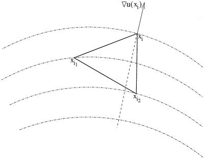
A key feature of Eikonal equations is that their characteristic lines coincide with the gradient lines of the viscosity solution u(x); this allows the construction of single-pass algorithms. This property guarantees that if xi1, xi2 ∈ N(xi) are such that the characteristic for the mesh point xi lies in the acute simplex xixi1xi2, and if that simplex is sufficiently small, then u(xi) ≥ max(u(xi1), u(xi2)) (see Fig. 1, for example).
Figure 1.
The characteristics and the gradient lines are the same for the Eikonal equation. If the characteristic lies in the simplex xixi1xi2, then the gradient ∇u(xi) points from that simplex.
This observation has been used to build two different fast Dijkstra-like methods for the Eikonal equation: Tsitsiklis' Algorithm (8) and Sethian's Fast Marching Method (9). By using different upwinding discretizations H̄(Ui, Ui1, Ui2, xi) = 1 of the Eikonal equation, Tsitsiklis (8) and Sethian (10) have shown that the following causality property holds, namely:
If xixi1xi2 is an acute simplex containing the characteristic for xi then the computed Ui ≥ max(Ui1, Ui2), regardless of the size of that simplex.(*)
A control–theoretic single-pass algorithm for the Eikonal equation.
Tsitsiklis' algorithm evolved from studying isotropic min-time optimal trajectory problems. Tsitsiklis has shown that Property (*) holds for the first-order control–theoretic upwinding discretization‡
 |
7 |
where τ(θ) = ∥θxi1 + (1 − θ)xi2 − xi∥. If θ0 is the minimizer, then the direction (θ0xi1 + (1 − θ0)xi2 − xi) is the approximation of the characteristic direction for xi. The dynamic programming motivation and further details can be found in ref. 8.
A finite-difference single-pass algorithm for the Eikonal equation.
The Fast Marching Method evolved from studying isotropic front propagation problems. Sethian has shown that the Property (*) holds for the following finite-difference upwinding discretization.§ Let P1 = (xi − xi1)/∥xi − xi1∥ and P2 = (xi − xi2)/∥xi − xi2∥. If P is the matrix with rows P1 and P2, then Eq. 6 can be rewritten as
 |
8 |
This quadratic equation is solved for Ui, and the additional upwinding requirement is verified (see ref. 13 for details).
The causality property guarantees that the discretized equations can be solved one by one (i.e., not simultaneously) if one solves them in the order of increasing values of U; thus, each of the two presented fast Eikonal solvers can be considered as a decoupling of a particular coupled discretization.
If the ascending ordering of the mesh points based on U were a priori known, these methods would have a computational complexity of O(M). Since the ordering has to be determined in the process of computation, both methods resolve this problem in the manner similar to Dijkstra's method, and the resulting complexity is O(M log M).
Higher-order versions of the Fast Marching Method together with numerical convergence tests are presented in ref. 6. Extensions to triangulated manifolds are derived in refs. 12, 13. Some early applications of the methodology include photolithography in ref. 9, a comparison of a similar approach with volume-of-fluid techniques in ref. 14, and a fast algorithm for image segmentation in ref. 15.
Static Hamilton–Jacobi Equations
We now introduce a family of single-pass methods for a much more general class of PDEs, namely
 |
9 |
where q and H are assumed to be Lipschitz-continuous, and the Hamiltonian H is also assumed to be convex and homogeneous of degree one in the first argument: H(∇u, x) = ∥∇u∥F((∇u/∥∇u∥), x) for some function F. We will further assume that 0 < F1 ≤ F(p, x) ≤ F2 < ∞ for all p and x.
This equation can also be viewed in different frameworks:
- Anisotropic front expansion (contraction) problems, in which the speed of the front F in the normal direction depends not only on the position but also on the current orientation of the front, provided that the resulting Hamiltonian is convex. For example, consider the front propagation problem
where the speed F((∇u/∥∇u∥), x) = ((∇u/∥∇u∥)⋅v)2 + 1, with a given vector v. This corresponds to anisotropic front motion, in which the fastest speed occurs when the normal to the front is pointing in the direction ±v.
10
- Anisotropic min-time optimal trajectory problems, in which the speed of motion depends not only on position but also on direction. The value function u for such problems is the viscosity solution of the static Hamilton–Jacobi–Bellman equation
• In this formulation, a is the unit vector determining the direction of motion, f(a, x) is the speed of motion in the direction a starting from the point x ∈ Ω, and q(x) is the time penalty for exiting the domain at the point x ∈ ∂Ω. The maximizer a corresponds to the characteristic direction for the point x. If f does not depend on a, Eq. 11 reduces to the Eikonal equation (see ref. 16). For background discussion of control theory, see refs. 3, 7, 11, 16, or 17.
11
In refs. 17 and 22, we explore the connections between these two application domains.¶
Characteristics vs. Gradients.
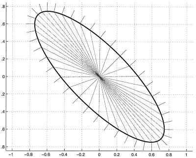
Building a single-pass ordered upwind method for these anisotropic problems described by Eq. 9 is considerably more challenging than for the Eikonal case, because the characteristics no longer coincide with the gradient lines of the viscosity solution. As a result, the characteristics and gradient lines may in fact lie in different simplexes (see Fig. 2).
Figure 2.
The characteristics and gradient directions for the expanding ellipse.
In fact, even if the characteristic for x lies in the simplex xx1x2, it is still possible that u(x) is smaller than u(x1) or u(x2). This is precisely why both the Fast Marching Method and Tsitsiklis' Algorithm cannot be directly applied in the anisotropic (non-Eikonal) case: it is no longer possible to decouple the system by computing/accepting the mesh points in ascending order. Thus, we must devise a causality relationship more carefully.
Ordered Upwind Methods.
In order to build single-pass methods for this more general equation, we capitalize on the more fundamental properties of the Hamilton–Jacobi–Bellman PDEs, namely, that the viscosity solution u of Eq. 9 is monotone increasing along the characteristic.
Even though the gradient lines and characteristics are not the same, our assumptions about F being bounded and bounded away from zero allow computation of a local bound on the difference between the characteristic and the gradient direction. In refs. 17 and 22, we prove the following three lemmas about the viscosity solution u:
- Lemma 1. Let a be the characteristic direction for x ∈ Ω. If ∇u(x) is well defined and γ is the angle between the vectors a and (−∇u(x)), then

12
- Lemma 2. Consider the characteristic passing through a point x̄ ∈ Ω and a level curve u(x) = C, where qmax < C < u(x̄). The characteristic intersects that level set at some point x̃. If x̄ is distance d away from the level set, then

13
- Lemma 3. Consider an unstructured mesh X of diameter h on Ω. Consider a simple closed curve Γ lying inside Ω with the property that, for any point x on Γ, there exists a mesh point y inside Γ such that ∥x − y∥ < h. Suppose the mesh point x̄i has the smallest value u(x̄i) of all of the mesh points inside the curve. If the characteristic passing through x̄i intersects that curve at some point x̃i, then
Building on these results, we construct the following fast ordered upwind method. As before, mesh points are divided into three classes (Far, Considered, Accepted). The AcceptedFront is defined as a set of Accepted mesh points, which are adjacent to some not-yet-accepted mesh points. Define the set AF of the line segments xjxk, where xj and xk are adjacent mesh points on the AcceptedFront, such that there exists a Considered mesh point xi adjacent to both xj and xk. For each Considered mesh point xi, we define the part of AF “relevant to xi”:
14
We will further assume that some consistent upwinding update formula is available: if the characteristic for xi lies in the simplex xixjxk, then Ui = G(Uj, Uk, xi, xj, xk). For the sake of notational simplicity, we will refer to this value as Gj,k.
- (i)
- Start with all mesh points in Far (Ui = ∞).
- (ii)
- Move the boundary mesh points (xi ∈ δΩ) to Accepted (Ui = q(xi)).
- (iii)
- Move all mesh points xi adjacent to the boundary into Considered and evaluate the tentative value of Ui = min(xj, xk)NF(xi) Gj,k.
- (iv)
- Find the mesh point xr with the smallest value of U among all the Considered.
- (v)
- Move xr to Accepted and update the AcceptedFront.
- (vi)
- Move Far mesh points adjacent to xr into Considered.
- (vii)
- Recompute the value for all the Considered xi within the distance h(F2/F1) from xr. If the new computed value is less than the previous tentative value for xi, then update Ui.
- (viii)
- If Considered is not empty, then go to iv.
Efficiency: This results in a “single-pass” method, because the maximum number of times each mesh point can be re-evaluated is bounded by the number of mesh points in the h(F2/F1) neighborhood of that point. Thus, this method formally has the computational complexity of
 Moreover, because the AcceptedFront is approximating the
level set of the viscosity solution u, as the mesh is
refined, the complexity will behave as

- Convergence: Convergence of the method depends on the upwinding update formula Ui = G(Uj, Uk, xi, xj, xk). In refs. 17 and 22, we prove the convergence to the viscosity solution of PDE 11 by using the particular update formula
where τ(θ) = ∥θxj + (1 − θ)xk − xi∥ and a = (θxj + (1 − θ)xk − xi)/τ(θ). This upwinding formula is the anisotropic generalization of update formula 7 for the Eikonal equation; it is also used as a building block for the general numerical scheme described in refs. 11 and 3. That scheme computes Ui on the basis of NU(xi), i.e., all xj, xk immediately adjacent to xi are considered. Unfortunately, that scheme also leads to the coupled system of M nonlinear equations, which cannot be directly decoupled due to the difference between the gradient and characteristic directions. Thus, our method can be considered as an indirect decoupling of the scheme described in refs. 11 and 3.
15
Numerical Results
In this section, we consider three different test problems, each of which can be described by a non-Eikonal (anisotropic) Hamilton–Jacobi PDE. In each case, the speed function is assumed to be known from the characterization of a particular application domain. For example, in the optimal trajectory test problem, f(x, a) reflects assumptions about the speed of the controlled vehicle, whereas in the seismic imaging test problem, the front expansion speed F is derived using assumptions about the elliptical nature of the “impulse-response surface” for the anisotropic medium.
Geodesic Distances on Manifolds.
The first test problem is to find the geodesic distance on the manifold z = g(x, y). As described in refs. 6 and 12, this can be accomplished by approximating the manifold with a triangulated mesh and then solving the distance equation ∥∇u∥ = 1 on that mesh. Since the latter equation is Eikonal, the Fast Marching Method can be used to solve it efficiently. However, if one desires to formulate the problem in the x-y plane instead of the intrinsic manifold coordinates, then the corresponding equation for u is not Eikonal. Indeed, the geodesic distance function u has to satisfy Eq. 9 with the speed function F defined as:
 |
16 |
where ω is the angle between ∇u(x, y) and the positive direction of the x axis. The degree of anisotropy in this equation is substantial, because the dependence of F on ω can be pronounced when ∇g is relatively large.‖
As noted in Static Hamilton–Jacobi Equations, u can also be considered as a value function for the corresponding min-time optimal trajectory problem and must, therefore, satisfy Eq. 11. Using the homogeneous Legendre transform on F, we obtain the speed function f(a, x, y) for the optimal trajectory problem:
 |
17 |
where a is a vector of unit length, and f is the control-theoretic speed of motion in the direction a (see ref. 17 and an unpublished work for details).
As an example, we consider the manifold
 |
and compute the geodesic distance on it from the origin (see Fig. 3). The “anisotropy coefficient” for this problem is
 |
We have performed the calculations using the first-order discretization 15 on a regular mesh with 292 × 292 mesh points.
Figure 3.
The geodesic distance from the origin on the manifold z = 0.75 sin(3πx) sin(3πy) computed on the square [−0.5, 0.5] × [−0.5, 0.5] in the x-y plane.
Min-Time Optimal Trajectory.
Our second example is a particular min-time optimal trajectory problem. Suppose that a vehicle's dynamics z(t) in the square [−0.5, 0.5] × [−0.5, 0.5] is described by
 |
18 |
 |
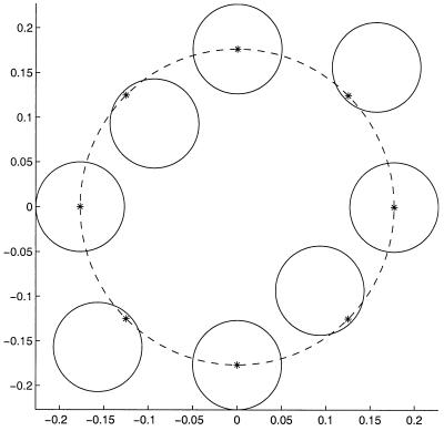
where the advection velocity b : R2 → R2 is known and ã : R+,0 → S1 is the control. We further assume that ∥b(x, y)∥ < 1 for all (x, y) ∈ [−0.5, 0.5] × [−0.5, 0.5]. The optimal control ã(⋅) will minimize the time it takes for the vehicle to reach the origin from the point x. The value function u(x) corresponding to that minimal time is the viscosity solution of the Hamilton–Jacobi–Bellman Eq. 11 with the boundary condition u(0, 0) = 0. The speed profile for the point x is a unit circle displaced by vector b(x, y) (see Fig. 4, for example). The corresponding speed function is
 |
19 |
where the direction of motion is 
Figure 4.
The vehicle's speed profiles for eight different points on the circle.
If b(x, y) =
 then we can rewrite the Hamilton–Jacobi PDE satisfied by
u(x, y) as follows:
 |
20 |
 |
As an example, we consider a particular advection velocity
b(x, y) =
 (see Fig. 5). The “anisotropy
coefficient” for this problem is
 |
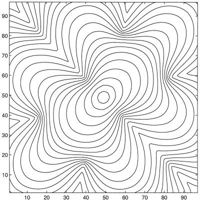
We have performed the calculations using the first-order discretization 15 on a regular mesh with 96 × 96 mesh points.
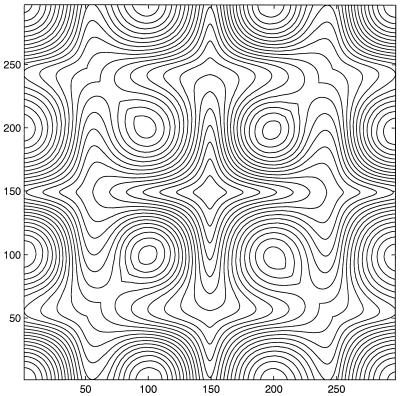
Figure 5.
The value function for the min-time optimal trajectory problem. The
vehicle's speed profile at every point (x, y) is the unit
circle displaced by the vector b(x, y) =
(−0.9sin(4πx)sin(4πy)/ )(x, y).
First Arrivals in Inhomogeneous Anisotropic Medium.
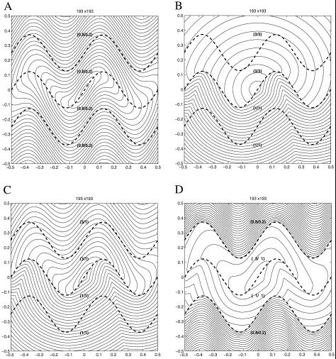
Finally, we include an example of first arrival travel times with applications to seismic imaging. We start with a computational domain that suggests material layering under a sinusoidal profile. The computational domain is the square [−a, a] × [−a, a], with layer shapes
 |
21 |
where A is the amplitude of the sinusoidal profile, m is the number of periods, and β is the phase offset. The domain is split into n layers by the curves yi(x) = C(x) + bi, where i = 1, … , (n − 1).
In each layer, the anisotropic speed at a point (x, y) is given by an ellipse with bigger axis (of length 2F2) tangential to the curve C(x) and the smaller axis (of length 2F1) normal to the curve. F1 and F2 are constants in each layer. Thus, the ellipse's orientation and shape depend on the local position.
This leads to an anisotropic Hamilton–Jacobi equation of the form:
 |
22 |
where the speed profile at any point (x, y) satisfies
 |
23 |
with
 |
Here, F1 and F2 are the ellipse semiaxes for the layer corresponding to the point (x, y).
The results are shown in Fig. 6. We take a = 0.5, A = 0.1225, m = 2, β = 0, and layer offsets bi = (−0.25, 0, 0.25). All calculations are on a 193 × 193 mesh. The (F2, F1) pair for each layer is given in Figs. 6 A–D.
Figure 6.
First arrivals in anisotropic media.
Acknowledgments
We thank L. C. Evans, M. Falcone, and O. Hald for valuable mathematical conversations and encouragement. This work was supported by the Applied Mathematical Sciences Office of Energy Research, U.S. Dept. of Energy (DE-AC03-76SF00098), Office of Naval Research (FDN00014-96-1-0381), and the Division of Mathematical Sciences, National Science Foundation.
Abbreviation
- PDE
partial differential equation
Footnotes
This paper was submitted directly (Track II) to the PNAS office.
See commentary on page 10992.
For the sake of notational clarity, we restrict our discussion to R2; all results can be restated for Rn and for meshes on manifolds.
In ref. 8, the property is proven for the discretization on a uniform Cartesian grid only; the corresponding lemma for triangulated acute meshes is proven in ref. 22. An iterative approach to the corresponding system of discretized equations was earlier used in refs. 3, 11, and 23.
In ref. 10, the property is proven for the first-order discretization on a uniform Cartesian grid; the property for triangulated acute meshes in R2 and Rn is proven in refs. 12 and 13. An iterative approach to the corresponding system of discretized equations on a uniform Cartesian grid was earlier used in ref. 4.
We show that all of the PDEs of the form (Eq. 9) can be produced as Hamilton–Jacobi–Bellman PDEs (Eq. 11) for min-time optimal trajectory problems. We show that the speed functions F and f are related by the homogeneous Legendre transform and that the function f generated from F will satisfy the same inequality 0 < F1 ≤ f(a, x) ≤ F2 < ∞ for all a and x. The geometric relationship between these two classes of problems is the basis for the alternative (anisotropic) Huyghens' construction using Wulff's shapes. This construction allows one to treat anisotropic front expansion/contraction problems by using the methods for the Hamilton–Jacobi–Bellman PDEs, provided the Hamiltonian H is convex. We note that aspects of these issues have been previously discussed in several specific contexts, including geometric optics (18), geophysics (19) and crystal growth (20).
The algorithm presented in ref. 12 on the manifold-approximating mesh is more efficient for this problem; here, it serves as a convenient test problem for the general anisotropic case: the numerical solution obtained by the Fast Marching Method on the manifold can then be compared to the solution obtained by the “general” method in the x-y plane. We note, of course, that only specific anisotropic problems can be converted into Eikonal equations on manifolds; see ref. 13 for details.
References
- 1.Crandall M G, Evans L C, Lions P-L. Trans AMS. 1984;277:487–502. [Google Scholar]
- 2.Crandall M G, Lions P-L. Trans AMS. 1983;277:1–43. [Google Scholar]
- 3.Gonzales R, Rofman E. SIAM J Control Optim. 1985;23:242–266. [Google Scholar]
- 4.Rouy E, Tourin A. SIAM J Num Anal. 1992;29:867–884. [Google Scholar]
- 5.Dijkstra E W. Numerische Mathematik. 1959;1:269–271. [Google Scholar]
- 6.Sethian J A. Level Set Methods and Fast Marching Methods: Evolving Interfaces in Computational Geometry, Fluid Mechanics, Computer Vision and Materials Sciences. Cambridge, U.K.: Cambridge Univ. Press; 1999. [Google Scholar]
- 7.Falcone M, Giorgi T, Loreti P. SIAM J Appl Math. 1994;54:1335–1354. [Google Scholar]
- 8.Tsitsiklis J N. IEEE Trans Automatic Control. 1995;40:1528–1538. [Google Scholar]
- 9.Sethian J A. Proceedings, SPIE 1996 International Symposium on Microlithography. Santa Clara, CA: SPIE; 1996. Fast Marching Level Set Methods for Three-Dimensional Photolithography Development. [Google Scholar]
- 10.Sethian J A. Proc Natl Acad Sci USA. 1996;93:1591–1595. doi: 10.1073/pnas.93.4.1591. [DOI] [PMC free article] [PubMed] [Google Scholar]
- 11.Kushner H J, Dupuis P G. Numerical Methods for Stochastic Control Problems in Continuous Time. New York: Springer; 1992. [Google Scholar]
- 12.Kimmel R, Sethian J A. Proc Natl Acad Sci USA. 1998;95:8431–8435. doi: 10.1073/pnas.95.15.8431. [DOI] [PMC free article] [PubMed] [Google Scholar]
- 13.Sethian J A, Vladimirsky A. Proc Natl Acad Sci USA. 2000;97:5699–5703. doi: 10.1073/pnas.090060097. (First Published May 16, 2000; 10.1073/pnas.090060097). [DOI] [PMC free article] [PubMed] [Google Scholar]
- 14.Helmsen J, Puckett E G, Colella P, Dorr M. SPIE 1996 International Symposium on Microlithography. Vol. 2726. Santa Clara, CA: SPIE; 1996. Two New Methods for Simulating Photolithography Development. [Google Scholar]
- 15.Malladi R, Sethian J A. Proc Natl Acad Sci USA. 1996;93:9389–9392. doi: 10.1073/pnas.93.18.9389. [DOI] [PMC free article] [PubMed] [Google Scholar]
- 16.Bellman R. Introduction to the Mathematical Theory of Control Processes. New York: Academic; 1967. [Google Scholar]
- 17.Vladimirsky A. Ph.D. thesis. Berkeley: Univ. of California; 2001. [Google Scholar]
- 18.McGulagh J. Trans Irish Acad. 1837;17:241–263. [Google Scholar]
- 19.Postma G W. Geophysics. 1955;20:780–806. [Google Scholar]
- 20.Schulze T P, Kohn R V. Phys Rev D. 1999;132:520–542. [Google Scholar]
- 21.Evans L C. Partial Differential Equations. Providence, RI: Am. Math. Soc.; 1998. [Google Scholar]
- 22.Sethian J A, Vladimirsky A. Center for Pure and Applied Mathematics Technical Report PAM-792. Berkeley: Univ. of California; 2001. [Google Scholar]
- 23.Kushner H J. Probability Methods for Approximations in Stochastic Control and for Elliptic Equations. New York: Academic; 1977. [Google Scholar]


