Abstract
A novel organic field effect transistor (OFET) -based biosensor is described for label-free glial fibrillary acidic protein (GFAP) detection. We report the first use of an extended solution gate structure where the sensing area and the organic semiconductor are separated, and a reference electrode is not needed. Different molecular weight polyethylene glycols (PEGs) are mixed into the bio-receptor layer to help extend the Debye screening length. The drain current change was significantly increased with the help of higher molecular weight PEGs, as they are known to reduce the dielectric constant. We also investigated the sensing performance under different gate voltage (Vg). The sensitivity increased after we decreased Vg from -5 V to -2 V, because the lower Vg is much closer to the OFET threshold voltage and the influence of attached negatively charged proteins become more apparent. Finally, the selectivity experiments toward different interferents were performed. The stability and selectivity are promising for clinical applications.
Keywords: OFET, biosensor, Debye screening length, Poly(ethylene glycol), GFAP detection
Graphical abstract
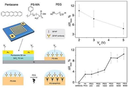
A novel organic field effect transistor-based biosensor is described for label-free glial fibrillary acidic protein detection. Different molecular weight polyethylene glycols were mixed into the bio-receptor layer to help extend the Debye screening length. The sensitivity increased while Vgdecreased since lower Vg is much closer to the OFET threshold voltage and the influence of attached proteins becomesmore apparent.
1. Introduction
Organic field effect transistors (OFETs) are an emerging alternative for sensing technology.[1-14] In the past two decades, these devices have garnered increasing interest for potential applications such as gas concentration and mechanical force sensing.[1, 9, 15] Also, because of inherent advantages including low cost, simple operation, large functional area and biocompatibility, FET based biosensors have been applied to detect many biological analytes.[8, 16-24]Since most of the bio-molecules influence electronic properties of liquids and/or their interfaces, label-free detection becomes possible by reading electrical signal changes. The analytes can be identified by either chemically binding specific receptors or modifying specific detection layers on the sensing area. Challenges in using this technology can include insufficient sensitivity, poor stability, and complicated fabrication processes.
Various possible mechanisms have been proposed for achieving better performance in OFET based biosensors. Most of the studies are based on the “bottom gate” and “solution gate” structure devices which put the solution sensing area upon the organic semiconductor and can exhibit relatively high sensitivities.[3, 5-6, 18, 20, 22] In order to protect the organic semiconductor from being influenced by water, several types of water-resistant layers have been attached or placed thereon. Unfortunately, these detectors can still have stability problems during prolonged detection times because most organic semiconductors are considerably sensitive to high humidity. In another approach, researchers have presented the “extended gate” structure device which can separate the sensing area from the transistor itself.[7, 25-28] In one promising example, Minami et al. developed a highly selective nitrate detector using one version of an extended gate geometry. This type of device shows improved stability, but almost all the devices in this architecture, including those from the Tokito group, need to add reference electrodes in the solution sensing area, bringing an additional degree of complication. Bonfiglio et al. proposed a concept of a remote floating gate influencing the current of the OFET, with the analyte solution capacitively coupled to the floating gate.[23-24] The detector functions as a label-free DNA sensor without a reference electrode, simultaneously having the advantages of simple structure and good stability. In Bonfiglio's architecture, a control capacitor separates the gate electrode from the surface of the substrate, and the floating gate connects this signal electrically to the base of the sensing area. In our work, we describe a novel extended “solution gate” structure device that differs from these aforementioned examples in a few key ways. Firstly, no reference electrode is required for our device functionality, simplifying the overall system. Secondly, the gate electrode is placed directly into the sensing solution electrolyte, altering the overall sensitivity of the device. The sensor can detect low-concentration, label-free protein analytes in solution in a stable manner.
The Debye screening length, beyond which voltage changes are not sensed in a solution, is a great challenge for FET based biosensors.[21, 29-30]To increase the length beyond bioanalyte/bioreceptor complex dimensions, sensors are often used in relatively low ionic strength solutions (i.e., 0.01X PBS, where PBS refers to the standard pH 7.4 “phosphate buffer solution” and X indicates dilution with water), that do not realistically represent biological fluids. It was reported that the polymer poly(ethylene glycol)(PEG) can substantially change the dielectric properties in aqueous solutions and thus serve to increase the sensing response seen at the calculated Debye length, thus increasing the “effective Debye screening length” for a given solution ionic strength, and the higher molecular weight PEG can decrease the dielectric constant more effectively than lower ones.[31] The Lieber group used PEG on the inorganic field effect transistor-based sensor for biodetection in high ionic strength solution (100 mM PBS).[30] Inspired by these previous studies, we further investigated the influences of different molecular weight polyethylene glycol (PEG)-containing bio-receptor layers to help overcome the Debye screening length.
Since one present clinical urgency is to investigate brain injuries as quickly as possible, we chose glial fibrillary acidic protein(GFAP) as a model analyte.[32-37] GFAP is a major protein associated with glial cells in the central nervous system, being released into human blood when brain injuries occur. The presence of 1.5 ng/ml GFAP in blood indicates that a patient has moderate brain damage.[37] The isoelectric points (pI points) for anti-GFAP antibody and GFAP are 5.7 and 5.4, respectively. According to our previous research, both GFAP and the corresponding antibody are negatively charged in pH=7.4 buffer solution.[38] Finally, we measured the sensitivity under different gate potential (Vg) for a further optimization. Dixon's Q tests on each group of data with removed outliers[39] was used to determine significant differences among bioreceptor material compositions.
2. Results and Discussion
2.1. Device Architecture and Chemical Characterization
Pentacene (Scheme 1a) was selected as the semiconductor material due to its high mobility and good stability. The OFET sensor consists of two major sections (shown in Scheme 1b): the drive unit (OFET) and the detection area (extended solution gate). For the drive unit, interdigitated Au electrodes were deposited on pentacene films to define a large active area (7 mm by 7 mm). It was found that interdigitated electrodes can yield increased absolute current changes due to increased surface area.[40] Therefore, the sensors can work under a low enough gate voltage (-2V) to maintain biological compatibility for proteins in aqueous solution. According to the typical transfer and output curves operated in air (shown in Figure 1), the devices show excellent linear and saturation regime characteristics with a hole mobility of 0.69 ± 0.07 cm2V-1s-1, an on/off ratio of 26.0 ±5.7 at Vg of -2 V and threshold voltage of 0.12 ± 0.1 V. The OFETs were working under Vds = -2 V and Vg = 0 to -2 V.
Scheme 1.
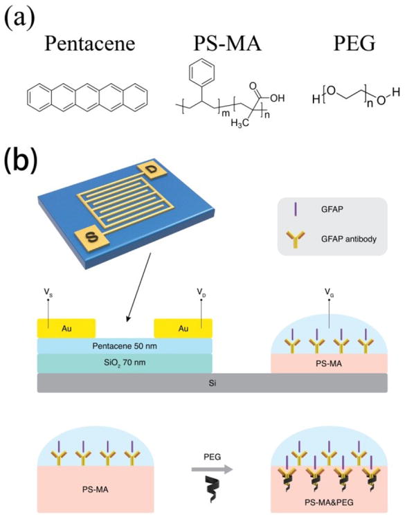
(a) Chemical structures of pentacene, PS-MA and PEG; (b) Device architecture of extended solution gate.
Figure 1.
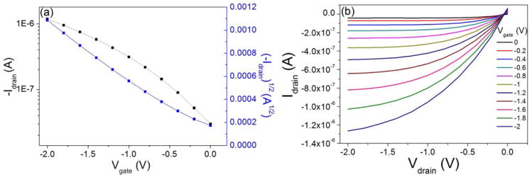
Typical (a) transfer curve and (b) output curve of a pentacene OFET tested in air.
On the extended solution gate, anti-GFAP was immobilized on the (1-Ethyl-3-(3-dimethylaminopropyl)carbodiimide) (EDC) /N-hydroxysuccinimide sodium (NHS) treated polystyrene-co-methacrylic acid (PS-MA) layer. The chemical structure of PS-MA is shown in Scheme 1a. EDC is soluble in water and most organic solvents, and is widely used in carboxylic group activation for dehydration-condensation reaction.[38] Since the EDC-derivatized compound is unstable, NHS is frequently used with EDC to increase coupling efficiency. The NHS-activated carboxyl groups of the polymer then react with a given antibody to immobilize it on the PS-MA layer. The chemical structure and reaction equation are shown in Figure S2. We use 1H-NMR to quantify the extent of carboxyl group as Figure S3. The 1H-NMR result shows that the styrene:methacrylic acid molar ratio is about 3:1. Before EDC/NHS treatment, the carboxylic acid 1H-NMR peak appears at 11.88 ppm. After EDC/NHS treatment, this peak completely disappears, indicating that 100% yield of carboxyl group activation was achieved. In addition, new proton peaks for NHS at 2.28 ppm and for EDC at 4 to 4.2 ppm were observed, indicating that the carboxylic acid groups were completely activated by EDC and NHS, desirable for high antibody surface coverage. Also, the morphology of the PS-MA film, EDC/NHS treated PS-MA film, and washed EDC/NHS treated PS-MA film were examined by optical microscopy, as shown in Figure S4. It can be observed that the PS-MA film provides a smooth surface. After treatment by EDC and NHS, the surface (Figure S4b) became rough because the concentrations of EDC and NHS are 3 times and 1.5 times higher than PS-MA in solution, respectively. The excess chemicals likely caused some aggregation of polymer and reactant, as visible from some small particulates forming in solution even after filtration through a 0.4-μm filter. These particulates were not observed when EDC and NHS were not added to solution. After washing the surface with DI water, the film surface (Figure S4c) regained some smoothness, as the DI water removed this unbound particles. Roughness measurements were taken of both substrates with and without 8000-MW PEG using an optical microscope and associated software (shown in Figure S4d and e). The images show no indication of obvious phase separation. Even though the roughness increased from 1.3μm to 3.1μm with the addition of PEG, the PEG-containing sample, if anything, showed more uniform morphology than the non-PEG sample and the feature shapes are similar in both samples. This indicates that there are not likely to be phase separated regions of predominantly polymer and predominantly PEG on the size scale of microns or larger. Also, the UV-vis transmission spectra of the two samples, corrected for thickness, are nearly identical (Figure S4f), indicating similar light-scattering features in both samples. Transfer curves for different molecular weight PEGs in liquid are shown in Figure S4g.
Furthermore, we put fluorescein isothiocyanate (FITC) labeled anti-GFAP on the bio-receptor layer to confirm the binding property between PS-MA and antibody. The images are shown in Figure 2. First, we put 100 μg/mL FITC labeled anti-GFAP directly on the bare substrate and PS-MA layer before activation by EDC/NHS (shown in Figure 2a and 2b). After 6 hours, the surfaces were washed by phosphate buffer solution (PBS) 5 times to remove any unbound anti-GFAP. We can see that hardly any antibody was immobilized on the substrate, indicating low non-specific binding. Figure 2c shows the result of the device modified by the EDC/NHS activated PS-MA layer. After FITC labeled anti-GFAP was applied to the device with the same procedure, visible florescence was observed. Compared to Figure 2b, we can see the antibody was immobilized on the PS-MA surface, indicating that the EDC/NHS activation is effective. Figure 2d shows the substrate with activated PS-MA with the addition of PEG (8000) which was added to the solution prior to spin coating. After we put FITC labeled anti-GFAP on it, the florescence intensity increased significantly compared with Figure 2c. An explanation for this is as follows. According to the previous report, PEG can help increase the light collection efficiency and enhance the florescence intensity.[41] Inspired by enzyme linked immunosorbent assay (ELISA) experiments, we used a “sandwich structure” method to further confirm that the native binding functionality of anti-GFAP antibody to the GFAP protein was not compromised; the results are shown in Figure S5 in supporting information. Hereon, we modified the normal anti-GFAP on the PS-MA layer with the same steps described in the experimental section, and then put 100 μg/mL GFAP on the device for 0.5 hour to let all the anti-GFAP binding with GFAP as thoroughly as possible. After washing 5 times with 0.05X PBS (Figure S6), we put 100 μg/mL FITC labeled anti-GFAP on the device for 0.5 hour and then again washed 5 times with 0.05X PBS (scheme shown in Figure S5a). The fluorescence microscope image is shown in Figure S5b, on which the green florescence is still apparent. As a control experiment, we used a readily available penicillin binding protein 2a (PBP2a) instead of GFAP keeping other steps the same. Based on the result shown in Figure. S5c, it is difficult to find any green florescence from FITC, indicating that anti-GFAP and GFAP bind together specifically.
Figure 2.
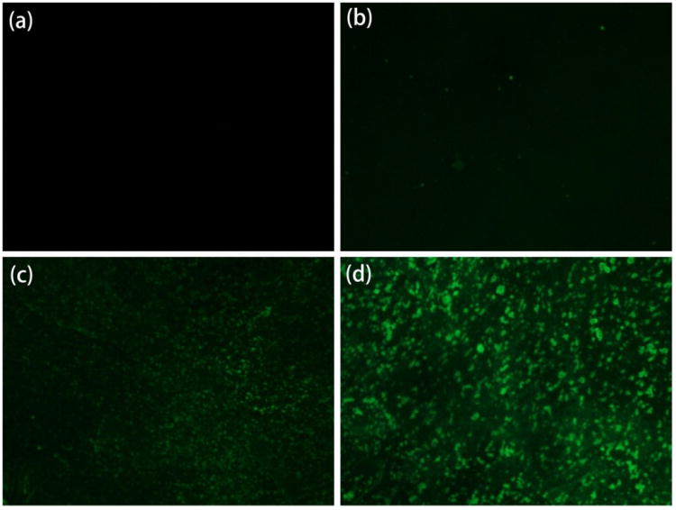
Fluorescence microscope images: (a) bare substrate; (b) PS-MA layer without activated by EDC/NHS; (c) PS-MA layer after activated by EDC/NHS; (d) activated PS-MA with PEG (8000) on exposure to 100 μg/mL FITClabeled anti-GFAP.
In an additional FITC experiment (Figure S6), biotin and FITC-marked streptavidin (known to form a very strong complex together) were used to show the quantity of binding that occurs on samples with and without the addition of PEG. Biotin was covalently bound to the surface of our substrate and subsequently exposed to FITC-streptavidin (simulating an antibody-protein complex). The presence of PEG had no effect on the overall fluorescence intensity in the streptavidin-exposed samples, indicating that the PEG is not responsible for increasing binding of protein to antibodies.
2.2. Sensing capabilities
The sensing capabilities of anti-GFAP modified OTFT devices with the help of different molecular weight PEGs (200, 400, 1000, 4000, 6000 and 8000, respectively) were first determined by measuring drain current changes on exposure to 100 ng/mL GFAP solution, the data is shown in Table S1 (Supporting Information). A schematic of the proposed sensing mechanism is shown in Figure 3a. GFAP is negatively charged in pH = 7.4 PBS, and it was tested by zeta potential measurement in our previous work which involve coating GFAP on a latex particle and measuring the resulting change in zeta potential.[38] After the protein was bound to anti-GFAP, the negatively charged species induced higher conductance in p-channel transistors. The negatively charged target proteins induce more negative potential in the extended gate and pull charge carriers (holes) close to the channel region of the p-channel semiconductor and thereby enhance the drain current. The data are shown in Figure 3b. Each data point was repeated five times and reported as an average, with error bars indicating one standard deviation. It is obvious that the three high molecular weight PEGs lead to significantly current change (p-value 1%), in which the low molecular weight PEGs were quite close to the “no PEG” control samples. As illustrated in Figure 3a, proteins can penetrate the PS-MA layer, having lower ion density because of the PEG, and bind to antibodies in an environment which has an increased sensing response, as if the Debye screening length were longer than it actually is in this analyte solution (calculated as approximately 0.7 nm in 1X PBS, to 7.3 nm in 0.01X PBS). The sensing properties for different analyte solutions (1X PBS to 0.05X PBS) were also recorded and are shown in Figure S7. According to a previous report,[31] high molecular weight PEGs can reduce the dielectric constant more effectively than lower ones, consistent with the result that high molecular weight PEG mixed devices can achieve larger current change using similar protein concentrations and device configurations. The drain current change of no antibody device was also recorded and shown in Figure S8. There is no obvious current change after the device was exposed to 100 ng/mL GFAP.
Figure 3.
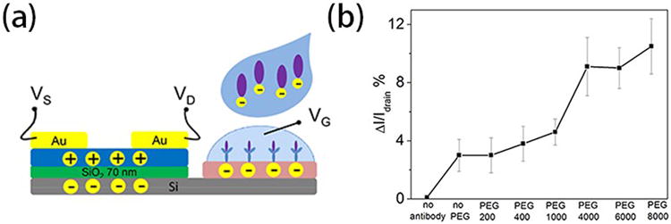
(a) Schematic of proposed sensing mechanism of the extended solution gate device. (b) Representative drain current changes of anti-GFAP modified extended solution gate devices on exposure to 100 ng/mL GFAP in 0.05X PBS. PS-MA films were mixed with different molecular weight PEGs. Gate voltage (Vg) and drain voltage (Vd)were set to -2 V relative to the source voltage(Vs).
Furthermore, we investigate the drain current changes on exposure to 100 ng/mL GFAP solution under different gate voltage (Vg), as we show in Figure 4, where again each data point was repeated at least five times. According to the results, the current changes increased significantly from 4.8% to 10.5% while Vg was decreased from -5 V to -2 V. The logical explanation is that the decreasing Vg set the device to a gate voltage which is much closer to the threshold voltage. When the negatively charged species were attached to the extended solution gate, the influence in drain current change was obvious. Because the lowest possible voltage increases compatibility with aqueous biomolecule solutions, we set Vg as -2 V for all the other tests in this paper.
Figure 4.
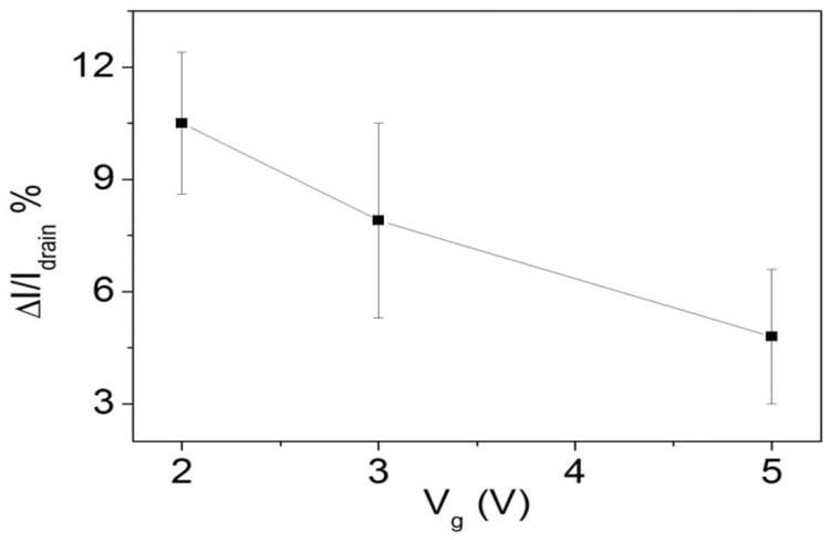
Drain current changes of anti-GFAP modified extended solution gate devices on exposure to 100 ng/mL GFAP solution with different Vg.
The responses of the sensors to different protein concentration were observed in a range of 0.5 to 100 ng/mL; the data are shown in Table S2 (Supporting Information). The detection limit of this sensor is calculated as 1.0 ng/mL based on a noise reading of 1.75 (calculation based on our blank samples), and the average current change for that concentration is 2.4% (shown in Figure 5). The continuous testing on one device indicates good stability of the GFAP sensor. In a related control experiment, devices lacking antibody were also measured by directly exposing PS-MA film to 100 ng/mL GFAP solution, and there is almost no current change (shown in Figure S8).
Figure 5.
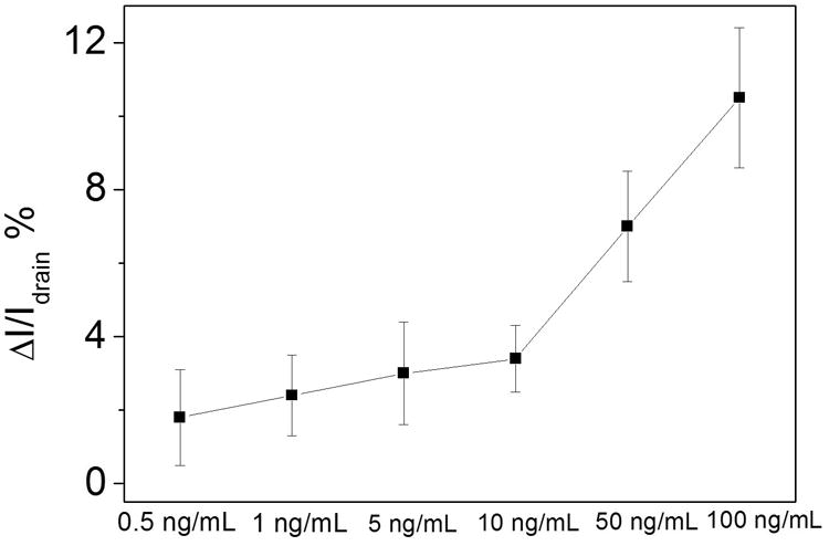
Drain current change of anti-GFAP modified devices.
To further portray the stability of the extended solution gate sensor, drain current changes were recorded every 2 minutes during a 30 minute period after 0.05X PBS was dropped on the device. The final drain current change was no more than 6% compared with Idrain0 (the first drain current of the device), as shown in Figure 6a. The slight drain current change, occurring over a much longer time than the responses to GFAP, can be attributed to the ions in PBS attaching to the PS-MA film.
Figure 6.
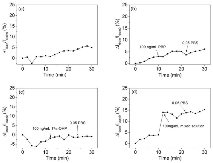
Drain current change of anti-GFAP modified devices (a) in 0.05X PBS for 30 min; (b) after 100 ng/mL PBP2a; (c) after 100 ng/mL 17α-OHP; (d) after the mixed solution (composed of 100 ng/mL PBP2a, 100 ng/mL 17α-OHP and 100 ng/mL GFAP) dropped on the anti-GFAP modified device.
We also performed selectivity experiments, as an initial investigation of whether this type of sensor could provide a GFAP response in the presence of other bioanalytes. We chose penicillin binding protein 2a (PBP2a), an appropriately sized protein with a similar negative charge at neutral pH,[42] and small molecule17α-hydroxyprogesterone (17α-OHP) of the physiologically relevant steroid hormone family as interferents,[43] both of them at 100 ng/mL in 0.05X PBS, the same concentration as used for GFAP. As shown in Figure 6b and c, the drain current changes were slight. Finally, to ensure that the GFAP signal was observable over signals from interfering analytes, we mixed PBP2a, 17α-OHP and GFAP together in 0.05X PBS. All the concentrations of these materials are 100 ng/mL, data from which are shown in Figure 6d. After the mixed solution was dropped on the device, a dramatic drain current change was observed. The current change ratio is 9.9% (after correcting for drift in the base line), which is similar to the pure GFAP current change we measured, and also on a faster time scale than current changes seen in drift and control experiments. This provides a preliminary indication that our device can signal the presence of GFAP in a more complex environment.
A plausible explanation for the increase of current change after PEG was mixed in the bio-receptor layer is as follows. The increased drain current change can be attributed to the presence of high molecular weight PEGs. Since high molecular weight PEGs can effectively reduce the dielectric constant and keep a low ion density environment for the binding proteins, the effective-Debye screening length increased, potentially leading to a larger drain current response. We also considered the possibility that the presence of the high molecular weight PEG promoted the penetration of analyte protein deeper into the receptor layer. However, in an addition fluorescence experiment shown in the supporting information (Figure S6) we saw that the attached protein concentration did not increase in the presence of PEG on the film. This supports the earlier explanation.
3. Conclusion
In summary, we described a novel OFET based biosensor with an extended solution gate structure for label-free GFAP detection with a limit of detection well within the concentration of interest. The extended solution gate structure separates the sensing area from the semiconductor and works without the help of the reference electrode, which combines stability and simplicity. The bio-receptor layers of our devices were mixed with different molecular weight PEGs to help overcome the Debye screening length limitations. As a result, we found that higher molecular weight PEGs can help the sensor achieve better sensitivity. Different Vg were also investigated from -5 V to -2 V, showing that the sensitivity is higher under a lower Vg. Finally, the stability and selectivity were observed by recording real-time drain current changes and putting different interferent solutions on the devices. The sensor could sense GFAP in the presence of the interferents. The results establish the use of the extended solution gate and moderately polar bioreceptor layer additives as synergistic strategies for improving protein biosensor performance.
3. Experimental Section
Materials and Devices Fabrication
All the chemical materials were purchased from Sigma-Aldrich without further purification. GFAP from human brain and polyclonal anti-GFAP (ab4674) were purchased from EMD Millipore. Buffer solution was purchased as10X concentrated PBS for bioreagent, “suitable for cell culture and molecular biology”. Highly n-doped <100> silicon wafers (as gate electrodes) with 70 nm SiO2 (as dielectric layers) were divided into 1 in. by 1 in. substrates. After cleaning by piranha solution (DANGER corrosive!), they were sonicated in water, acetone and isopropanol, and then dried by forced N2. Substrates were further cleaned by oxygen plasma (100 W, 3 min) and then annealed in a 100 °C vacuum oven with exposure to hexamethyldisilazane (HMDS) for 2 hours. Next, pentacene was thermally evaporated on half of each HMDS-treated substrate surface with a thickness of 50 nm at a rate of0.4Å/s. The chamber pressure during deposition was lower than 4×10⁻⁶ Torr. Then, gold electrodes (50 nm) were thermally evaporated through an interdigitation mask (shown in Fig. S1 in supporting information) and deposited on the pentacene film with a chamber pressure about 5×10⁻⁶ Torr. The rate was 0.4Å/s and the channel width/length was 28 (W = 7 mm, L = 0.25 mm).
Antibody immobilization
On the other half of each substrate, we manually etched 8 mm by 8 mm SiO2 to expose silicon for the extended solution gate sensing area. The carboxylic acid groups of PS-MA were activated by EDC and NHS. Normally, 10 mg PS-MA and 30 mg EDC were first dissolved in 0.5 mL anhydrous dichloromethane (DCM) and 0.5 mL anhydrous N,N′-dimethylformamide (DMF) mixed solvent. After stirring at room temperature for 1 hour, 15 mg NHS was then added into the mixture with stirring for another 2 hours. The resulting mixture was purified though a 0.45 μm filter and then mixed with 5 mg/mL of one of a series of different molecular weight PEG (200, 400, 1000, 4000, 6000 and 8000), with continued stirring at room temperature for half hour. The final mixture was spin-coated on the exposed silicon at a speed of 3000 rpm for 90 seconds. Then the device surface was carefully washed with DI water to remove excess EDC and NHS and dried in room temperature for antibody modification. Anti-GFAP (1 mg/mL in 0.05X PBS) was covalently attached to the activated PS-MA surface for 6 hours and then gently washed with PBS to remove any non-covalently bound antibodies. To avoid water evaporation and antibody contamination, the samples were maintained in a humid sealed vessel during the reactions. As control experiments: the devices without anti-GFAP were prepared by putting one drop of 0.05X PBS on the EDC/NHS activated PS-MA film for 6 hours; activated PS-MA without PEG was prepared to make devices with the same steps to compare the influence of PEG.
Apparatus
Electronic analysis of OFETs was conducted on an Agilent 4155C semiconductor parameter analyzer in air. 1H-NMR spectra were recorded on Bruker Avance (300 MHz/400 MHz) spectrometers. The oxygen plasma treatments were done on a Technics West Inc. (PE II A) plasma system. Florescence images were taken by the florescence microscope Olympus IX71.
Supplementary Material
Acknowledgments
We thank the National Institutes of Health for funding. Research reported in this publication was supported by the National Institute Of Biomedical Imaging And Bioengineering of the National Institutes of Health under Award Number R21EB018426. The content is solely the responsibility of the authors and does not necessarily represent the official views of the National Institutes of Health. J.D. thanks the National Science Foundation for a Predoctoral Fellowship. The authors appreciate Mr. Su-Chang Mun's graphical artworks.
Footnotes
Supporting Information: Supporting Information is available from the Wiley Online Library or from the author.
Contributor Information
Jian Song, Department of Materials Science and Engineering, Johns Hopkins University, 3400 North Charles Street, Baltimore, Maryland 21218, United States.
Jennifer Dailey, Department of Materials Science and Engineering, Johns Hopkins University, 3400 North Charles Street, Baltimore, Maryland 21218, United States.
Hui Li, Department of Materials Science and Engineering, Johns Hopkins University, 3400 North Charles Street, Baltimore, Maryland 21218, United States.
Hyun-June Jang, Department of Materials Science and Engineering, Johns Hopkins University, 3400 North Charles Street, Baltimore, Maryland 21218, United States.
Pengfei Zhang, Department of Materials Science and Engineering, Johns Hopkins University, 3400 North Charles Street, Baltimore, Maryland 21218, United States; Department of Biomedical Engineering, Johns Hopkins University, 3400 North Charles Street, Baltimore, Maryland 21218, United States.
Jeff Tza-Huei Wang, Department of Materials Science and Engineering, Johns Hopkins University, 3400 North Charles Street, Baltimore, Maryland 21218, United States; Department of Biomedical Engineering, Johns Hopkins University, 3400 North Charles Street, Baltimore, Maryland 21218, United States.
Allen D. Everett, Department of Materials Science and Engineering, Johns Hopkins University, 3400 North Charles Street, Baltimore, Maryland 21218, United States; Johns Hopkins Medical Institutes, Children's Center, 1800 Orleans Street, Baltimore, Maryland 21287, United States
Howard E Katz, Department of Materials Science and Engineering, Johns Hopkins University, 3400 North Charles Street, Baltimore, Maryland 21218, United States.
References
- 1.Zang Y, Zhang F, Huang D, Di CA, Zhu D. Adv Mater. 2015;27:7979. doi: 10.1002/adma.201503542. [DOI] [PubMed] [Google Scholar]
- 2.Minami T, Sasaki Y, Minamiki T, Wakida S, Kurita R, Niwa O, Tokito S. Biosens Bioelectron. 2016;81:87. doi: 10.1016/j.bios.2016.02.036. [DOI] [PubMed] [Google Scholar]
- 3.Shintani Y, Ibori S, Igarashi K, Naramura T, Inaba M, Kawarada H. Electrochim Acta. 2016;212:10. [Google Scholar]
- 4.Kaisti M, Zhang Q, Prabhu A, Lehmusvuori A, Rahman A, Levon K. IEEE Trans Electron Devices. 2015;62:2628. [Google Scholar]
- 5.Melzer K, Bhatt VD, Jaworska E, Mittermeier R, Maksymiuk K, Michalska A, Lugli P. Biosens Bioelectron. 2016;84:7. doi: 10.1016/j.bios.2016.04.077. [DOI] [PubMed] [Google Scholar]
- 6.Khim D, Shin EY, Xu Y, Park WT, Jin SH, Noh YY. ACS Appl Mater Interfaces. 2016;8:17416. doi: 10.1021/acsami.6b03671. [DOI] [PubMed] [Google Scholar]
- 7.Minamiki T, Minami T, Koutnik P, Anzenbacher P, Jr, Tokito S. Anal Chem. 2016;88:1092. doi: 10.1021/acs.analchem.5b04618. [DOI] [PubMed] [Google Scholar]
- 8.Magliulo M, Manoli K, Macchia E, Palazzo G, Torsi L. Adv Mater. 2015;27:7528. doi: 10.1002/adma.201403477. [DOI] [PubMed] [Google Scholar]
- 9.Zhang C, Chen P, Hu W. Chem Soc Rev. 2015;44:2087. doi: 10.1039/c4cs00326h. [DOI] [PubMed] [Google Scholar]
- 10.Martínez Hardigree JF, Katz HE. Accounts of Chem Res. 2014;47:1369. doi: 10.1021/ar5000049. [DOI] [PubMed] [Google Scholar]
- 11.Liao C, Yan F. Polym Rev. 2013;53:352. [Google Scholar]
- 12.Torsi L, Magliulo M, Manoli K, Palazzo G. Chem Soc Rev. 2013;42:8612. doi: 10.1039/c3cs60127g. [DOI] [PubMed] [Google Scholar]
- 13.Sokolov AN, Tee BCK, Bettinger CJ, Tok JBH, Bao Z. Accounts of Chem Res. 2012;45:361. doi: 10.1021/ar2001233. [DOI] [PubMed] [Google Scholar]
- 14.Operamolla A, Farinola GM. Eur J Org Chem. 2011;2011:423. [Google Scholar]
- 15.Huang W, Besar K, LeCover R, Rule AM, Breysse PN, Katz HE. J Am Chem Soc. 2012;134:14650. doi: 10.1021/ja305287p. [DOI] [PMC free article] [PubMed] [Google Scholar]
- 16.Manoli K, Magliulo M, Mulla MY, Singh M, Sabbatini L, Palazzo G, Torsi L. Angew Chem Int Edit. 2015;54:12562. doi: 10.1002/anie.201502615. [DOI] [PubMed] [Google Scholar]
- 17.Macchia E, Alberga D, Manoli K, Mangiatordi GF, Magliulo M, Palazzo G, Giordano F, Lattanzi G, Torsi L. Sci Rep. 2016;6:28085. doi: 10.1038/srep28085. [DOI] [PMC free article] [PubMed] [Google Scholar]
- 18.Magliulo M, De Tullio D, Vikholm-Lundin I, Albers WM, Munter T, Manoli K, Palazzo G, Torsi L. Anal Bioanal Chem. 2016;408:3943. doi: 10.1007/s00216-016-9502-3. [DOI] [PubMed] [Google Scholar]
- 19.Magliulo M, Mallardi A, Mulla MY, Cotrone S, Pistillo BR, Favia P, Vikholm-Lundin I, Palazzo G, Torsi L. Adv Mater. 2013;25:2090. doi: 10.1002/adma.201203587. [DOI] [PubMed] [Google Scholar]
- 20.Singh M, Mulla MY, Santacroce MV, Magliulo M, Di Franco C, Manoli K, Altamura D, Giannini C, Cioffi N, Palazzo G, Scamarcio G, Torsi L. J Phys D-Appl Phys. 2016;49:275101. [Google Scholar]
- 21.Palazzo G, De Tullio D, Magliulo M, Mallardi A, Intranuovo F, Mulla MY, Favia P, Vikholm-Lundin I, Torsi L. Adv Mater. 2015;27:911. doi: 10.1002/adma.201403541. [DOI] [PubMed] [Google Scholar]
- 22.Mulla MY, Tuccori E, Magliulo M, Lattanzi G, Palazzo G, Persaud K, Torsi L. Nat Commun. 2015;6:6010. doi: 10.1038/ncomms7010. [DOI] [PMC free article] [PubMed] [Google Scholar]
- 23.Lai S, Demelas M, Casula G, Cosseddu P, Barbaro M, Bonfiglio A. Adv Mater. 2013;25:103. doi: 10.1002/adma.201202996. [DOI] [PubMed] [Google Scholar]
- 24.Demelas M, Lai S, Casula G, Scavetta E, Barbaro M, Bonfiglio A. Sens Actuator B-Chem. 2012;171-172:198. [Google Scholar]
- 25.Tang W, Jiang C, Li Q, Hu W, Feng L, Huang Y, Zhao J, Chen S, Guo X. IEEE Electron Device Lett. 2016;37:1002. [Google Scholar]
- 26.Lin MY, Hsu WY, Yang YS, Huang JW, Chung YL, Chen H. Anal Bioanal Chem. 2016;408:4785. doi: 10.1007/s00216-016-9568-y. [DOI] [PubMed] [Google Scholar]
- 27.Al-Hardan NH, Abdul Hamid MA, Ahmed NM, Jalar A, Shamsudin R, Othman NK, Kar Keng L, Chiu W, Al-Rawi HN. Sensors. 2016;16:839. doi: 10.3390/s16060839. [DOI] [PMC free article] [PubMed] [Google Scholar]
- 28.Iskierko Z, Sosnowska M, Sharma PS, Benincori T, D'Souza F, Kaminska I, Fronc K, Noworyta K. Biosens Bioelectron. 2015;74:526. doi: 10.1016/j.bios.2015.06.073. [DOI] [PubMed] [Google Scholar]
- 29.Lemay SG, Laborde C, Renault C, Cossettini A, Selmi L, Widdershoven FP. Accounts of Chem Res. 2016;49:2355. doi: 10.1021/acs.accounts.6b00349. [DOI] [PubMed] [Google Scholar]
- 30.Gao N, Zhou W, Jiang X, Hong G, Fu TM, Lieber CM. Nano Lett. 2015;15:2143. doi: 10.1021/acs.nanolett.5b00133. [DOI] [PMC free article] [PubMed] [Google Scholar]
- 31.Arnold K, Herrmann A, Pratsch L, Gawrisch K. Biochim Biophys Acta-Biomembr. 1985;815:515. doi: 10.1016/0005-2736(85)90381-5. [DOI] [PubMed] [Google Scholar]
- 32.Hol EM, Pekny M. Curr Opin Cell Biol. 2015;32:121. doi: 10.1016/j.ceb.2015.02.004. [DOI] [PubMed] [Google Scholar]
- 33.Eng LF. J Neuroimmunol. 1985;8:203. doi: 10.1016/s0165-5728(85)80063-1. [DOI] [PubMed] [Google Scholar]
- 34.Ishida K, Kaneko K, Kubota T, Itoh Y, Miyatake T, Matsushita M, Yamada M. J Neurol Sci. 1997;151:41. doi: 10.1016/s0022-510x(97)00108-1. [DOI] [PubMed] [Google Scholar]
- 35.Mayer CA, Brunkhorst R, Niessner M, Pfeilschifter W, Steinmetz H, Foerch C. PLoS ONE. 2013;8:e62101. doi: 10.1371/journal.pone.0062101. [DOI] [PMC free article] [PubMed] [Google Scholar]
- 36.Kawata K, Liu CY, Merkel SF, Ramirez SH, Tierney RT, Langford D. Neurosci Biobehav Rev. 2016;68:460. doi: 10.1016/j.neubiorev.2016.05.009. [DOI] [PMC free article] [PubMed] [Google Scholar]
- 37.Korley FK, Diaz-Arrastia R, Wu A, Yue JK, Manley GT, Sair HI, Eyk JV, Everett AD. J Neurotrauma. 2016;33:215. doi: 10.1089/neu.2015.3949. [DOI] [PMC free article] [PubMed] [Google Scholar]
- 38.Huang W, Besar K, Le Cover R, Dulloor P, Sinha J, Martínez Hardigree JF, Pick C, Swavola J, Everett AD, Frechette J, Bevan M, Katz HE. Chem Sci. 2014;5:416. [Google Scholar]
- 39.Efstathiou CE. Talanta. 2006;69:1068. doi: 10.1016/j.talanta.2005.12.031. [DOI] [PubMed] [Google Scholar]
- 40.Frank A, Jr, Dorielle TP, Shekhar B. Journal of Physics: Conference Series. 2010;224:012134. [Google Scholar]
- 41.Gorocs Z, McLeod E, Ozcan A. Sci Rep. 2015;5:10999. doi: 10.1038/srep10999. [DOI] [PMC free article] [PubMed] [Google Scholar]
- 42.Helassa N, Vollmer W, Breukink E, Vernet T, Zapun A. FEBS J. 2012;279:2071. doi: 10.1111/j.1742-4658.2012.08592.x. [DOI] [PubMed] [Google Scholar]
- 43.Rebarber A, Fox NS, Klauser CK, Istwan NB, Rhea DJ, Stanziano GJ, Saltzman DH. J Matern-Fetal Neonatal Med. 2010;23:1139. doi: 10.3109/14767051003615418. [DOI] [PubMed] [Google Scholar]
Associated Data
This section collects any data citations, data availability statements, or supplementary materials included in this article.


