

Abstract
Purpose
The aim of this study was to find an optimized configuration of collimator angle, couch angle, and starting tracking phase to improve the delivery performance in terms of MLC position errors, maximal MLC leaf speed, and total beam‐on time of DCAT plans with motion tracking (4D DCAT).
Method and materials
Nontracking conformal arc plans were first created based on a single phase (maximal exhalation phase) of a respiratory motion phantom with a spherical target. An ideal model was used to simulate the target motion in superior‐inferior (SI), anterior‐posterior (AP), and left‐right (LR) dimensions. The motion was decomposed to the MLC leaf position coordinates for motion compensation and generating 4D DCAT plans. The plans were studied with collimator angle ranged from 0° to 90°; couch angle ranged from 350°(−10°) to 10°; and starting tracking phases at maximal inhalation () and exhalation () phases. Plan performance score (PPS) evaluates the plan complexity including the variability in MLC leaf positions, degree of irregularity in field shape and area. PPS ranges from 0 to 1, where low PPS indicates a plan with high complexity. The 4D DCAT plans with the maximal and the minimal PPS were selected and delivered on a Varian TrueBeam linear accelerator. Gafchromic‐EBT3 dosimetry films were used to measure the dose delivered to the target in the phantom. Gamma analysis for film measurements with 90% passing rate threshold using 3%/3 mm criteria and trajectory log files were analyzed for plan delivery accuracy evaluation.
Results
The maximal PPS of all the plans was 0.554, achieved with collimator angle at 87°, couch angle at 350°, and starting phase at maximal inhalation (). The maximal MLC leaf speed, MLC leaf errors, total leaf travel distance, and beam‐on time were 20 mm/s, 0.39 ± 0.16 mm, 1385 cm, and 157 s, respectively. The starting phase, whether at maximal inhalation or exhalation had a relatively small contribution to PPS (0.01 ± 0.05).
Conclusions
By selecting collimator angle, couch angle, and starting tracking phase, 4D DCAT plans with the maximal PPS demonstrated less MLC leaf position errors, lower maximal MLC leaf speed, and shorter beam‐on time which improved the performance of 4D motion‐tracking DCAT delivery.
Keywords: DCAT, MLC, motion tracking
1. INTRODUCTION
Dynamic conformal arc therapy (DCAT) technique has been implemented in linear accelerator (linac) based stereotactic body radiotherapy (SBRT) for patients with Stage I/II non‐small‐cell lung cancer (NSCLC).1, 2, 3, 4, 5, 6, 7, 8, 9 One advantage of DCAT technique is the robust and transferable treatment methodology in planning, which is capable of reproducing the same or similar optimized planning results on different planning systems.7, 8, 9, 10 Compared to three‐dimensional (3D) conformal radiation therapy (3DCRT), DCAT has been proven to achieve higher target dose conformity and normal tissue dose sparing as well as shorter beam‐on time for dose delivery.9, 10 Rauschenbach et al.10 stated that DCAT should remain an alternative to 3DCRT in facilities that do not have VMAT or IMRT. Shi et al.11 have successfully implemented DCAT technique into clinical use for lung SBRT. They reported that the plan quality of DCAT met the RTOG protocols. Ouyang et al.12 reported that combining flattening filter free beams and DCAT provides promising improvements in NSCLC SBRT treatment in both plan quality and treatment planning efficiency. In addition, unlike VMAT, tumor coverage is not affected by MLC interplay effect.
Although hypo‐fractionated radiotherapy has demonstrated capability of providing high local control rates (85%–98%) in several phase I/II trials,13, 14, 15, 16, 17, 18, 19 blurred dose caused by tumor motion entails an increased risk of normal tissue toxicity.20, 21 Shimizu et al.22 reported lung tumor motion in SI direction was up to 24 mm. Several studies reported over 10 mm tumor motion in AP and LR directions.23, 24, 25 Zhao and colleagues26 reported dose deviation with motion is larger for smaller lung tumor (i.e., gross target volume is less than 10 cm3 in their study). Therefore, it is especially important to manage respiratory motion in hypo‐fractionated lung SBRT to ensure more accurate dose delivery. Tumor motion tracking is a recent development toward improving dose delivery quality. Compared with the common techniques of motion management such as respiratory gating and forced shallow breathing, motion‐tracking technique provides shorter treatment delivery time and requires less patient co‐operation and causes less patient discomfort.27, 28, 29
The effects of plan parameters in motion tracking have not been fully studied. Several studies implemented motion tracking with dynamic MLC treatment delivery for either Varian or Elekta linac and reported improved target dose coverage without significantly increasing the total treatment time.30, 31, 32, 33, 34, 35 Sawant et al. developed lung tumor motion compensation method where target motion that is decomposed to the beam's eye view (BEV) is dependent on collimator, gantry, and couch angles.30 Different combinations of collimator and couch angles will result in different tracking complexity which affects the delivery performance. Therefore, optimization of collimator and couch trajectories may reduce the possibility of having plans running at the mechanical limits of the linac, which can improve the treatment efficiency and robustness.36, 37 In most published studies on VMAT plans with motion tracking, collimator, and couch angles for plans were set at 90° and 0°, respectively, which has been shown to be favorable for MLC tracking because the MLC leaf motion direction is parallel to target motion in superior‐inferior (SI) direction.30, 32, 34, 35 However, for (3D) motion tracking, this collimator angle may not be the optimal solution for motion tracking.
In this study, we investigated the effects of collimator angle and couch angle on the performance, including MLC leaf position errors, MLC leaf speed, and total beam‐on time of DCAT plans with motion tracking (i.e., 4D DCAT). In addition, we also evaluated the effect of different starting tracking phases on 4D DCAT performance.
2. METHODS
2.A. Respiratory three‐dimensional motion phantom and model
The QUASARTM respiratory motion phantom (Modus Medical Device Inc., Canada) and a Cedar cylindrical insert with a 30 mm off‐centered spherical target (22 mm diameter) for simulating 3D respiratory motion was used in this study (Fig. 1). A rotational stage hinged the insert with the phantom motor which allows the target to rotate with 60° of total motion range as it translates. As shown in Fig. 2, the target motion is the composite of reciprocating motion in the SI direction (z axis) and rotational motion in LR (left‐right, x axis) and AP (anterior‐posterior, y axis) plane. The target motion model is then given by
| (1) |
| (2) |
| (3) |
where = 20 mm was the peak‐to‐peak target motion amplitude, was the maximal rotational angle of the insert. The off‐center distance was 30 mm. is the breathing cycle period and was set to 6 s. , , and are the starting phase for motion tracking, and ranged from maximal exhalation phases () to maximal inhalation ().
Figure 1.

Respiratory motion phantom and setup. (a) Cedar insert with two off‐center hemispherical tumor phantoms. (b) The Cedar insert was hinged to the motor in the QUASAR phantom with a rotational stage to simulate 3D motion (photos were retrieved from http://modusqa.com/radiotherapy/phantoms/respiratory-motion, Modus Medical Device Inc., on October 22, 2016). (c) Two red markers were attached to the insert so that their positions could be tracked by two cameras.
Figure 2.
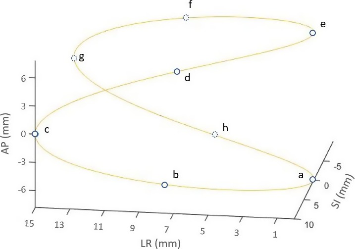
Illustration of spherical target motion according to the 3D rigid motion model. Blue circles represent the positions of target mass center at different time points. If the target starts to move from position “a,” then if follows the sequence of “a‐b‐c‐d‐e‐f‐g‐h‐a.”
2.B. Generating 4D DCAT plans
2.B.1. Nontracking DCAT Plans
All nontracking DCAT plans were generated based on CT images of a single respiratory phase (maximal exhalation phase), using EclipseTM treatment planning system (version 10.0, Varian Medical Systems, Inc., Palo Alto, USA), where collimator angle ranged from 0° to 90° with an increment of 1°, and couch angle ranged from 350° to 10° with an increment of 1°. Each plan was generated in the planning system with specific collimator and couch angle combination and exported as a DICOM plan file for motion compensation. Figure Figure A1A1 in Appendix A illustrates the collimator and couch angles in the treatment room setting. MLC leaves on both banks conformed to the contour of the stationary target during gantry rotation.
Each nontracking DCAT plan had 180 control points (CPs), with a full arc ranging from 181° to 179°. The collimator size (8 cm × 8 cm) was large enough to incorporate the target and its motion so that the collimator jaws would not block the beam during motion tracking. According to RTOG 0813, the prescription isodose surface for SBRT is normally chosen such that 95% of the PTV is conformably covered by the prescription isodose surface and 99% of the PTV receives a minimum of 90% of the prescription dose.38 For plans in this study, a simplified planning method was applied where 5 Gy (EBT3 film has high gradient response around 5 Gy) was prescribed to the isocenter set at the geometric center of the target with source to axis distance (SAD) of 100 cm.
2.B.2. Motion‐tracking plans
The 4D DCAT plans were generated by applying the lung tumor motion‐tracking algorithm. The motion‐tracking method was based on a priori known rigid sinusoidal motion model that was projected to the BEV and compensated by MLC leaves.
For motion parallel to the direction of leaf travel, , the position of leaf “m” of CP “n” in the nontracking DCAT plan was transformed using:
| (4) |
where the motion compensation along MLC leaf travel direction, , is described in Appendix A. For motion perpendicular to the direction of leaf travel, all in‐field MLC leaves would be shifted laterally according to the motion direction by the following equation:
| (5) |
where the motion compensation that is perpendicular to MLC leaf travel direction (), is described in Appendix A. MLC leaves of both 2.5 mm and 5.0 mm width were involved in target motion compensation.
An in‐house developed MATLAB program was used for generating 4D DCAT plans with constant dose rate. The tracking algorithm was based on the algorithm developed by Sawant et al. for motion compensation30 and studies on modifications of beam parameters to generate a linac deliverable plan.31, 33, 34, 35 All machine parameters such as MLC leaf speed, gantry speed, and gantry acceleration were within limits (Table 1) after MLC leaf modification. As illustrated in Fig. 3, when leaf positions were modified for each CP, the speed of each MLC leaf and gantry speed were calculated using the maximal allowable dose rate. If there was any leaf speed exceeded the limit, the maximal dose rate would be reduced to the next available one and the leaf compensations for all CPs would be recalculated. Then, leaf speed would be calculated again based on new leaf positions and dose rate. The maximal allowable dose rate would be iteratively adjusted until all leaf speed at any specific CP was within the limit. As a result, all the MLC leaves involved in tracking could have enough time to reach to the planned position for motion compensation with constant dose rate.
Table 1.
Machine constraints of the linear accelerator
| Machine parameter | Maximal valuea |
|---|---|
| Gantry speed (deg/s) | 6.0 |
| Gantry acceleration (deg/s2) | 0.75 |
| MLC leaf speed (mm/s) | 25.0 |
| Dose rate (MU/min) | 600 |
Reference: Varian Truebeam Datasheet.
Figure 3.

Flowchart of generating a deliverable 4D DCAT plan.
2.C. Plan Performance Score (PPS)
PPS was used to characterize the complexity degree of each 4D DCAT plan. PPS depends on the modulation complexity score (MCS),39 leaf travel index (LTI),39 and the maximal MLC leaf speed of a 4D DCAT plan with collimator angle at and couch angle at (eq. (6)). MCS focuses on the variability in MLC leaf positions, degree of irregularity in field shape, and area. These are related to the MLC aperture shape of each CP and leaf motion between adjacent CPs. As shown in Appendix A, motion projected to the BEV is dependent on collimator angle, couch angle, and starting phase. Therefore, PPS can be expressed as eq. (6).
| (6) |
MCS ranges from 0 to 1, and it approaches 0 for increasing degree of treatment plan complexity.39, 40, 41 LTI ranges from 0 to 1, and it approaches 0 for increasing total MLC leaf travel distance.39 PPS ranges from 0 to 1, a high PPS indicates that the plan of a specific configuration of collimator angle, couch angle, and starting phase has less degree of leaf position variability, aperture shape irregularity as well as low leaf speed.
A total of 3822 PPS values of 4D DCAT plans were calculated (91 collimator angles, 21 couch angles, and 2 starting tracking phases for 3D motion tracking). We selected the 4D DCAT plans with the minimal and the maximal PPS values, and corresponding nontracking DCAT plans for delivery experiments.
2.D. Experimental delivery of 4D DCAT Plans
In the simulation algorithm, we assumed that dose rate and MLC leaves of each CP could instantaneously reach to planned values without any fluctuations. However, in actual delivery, there is a finite time before dose rate reaches the planned value.31, 32, 35 By acquiring delivery parameters (e.g., MLC leaf position errors) of 4D DCAT plans, we could evaluate the discrepancy between plans generated by simulation algorithm and the actual delivered ones. 4D DCAT plans were delivered using Varian TrueBeamTM linac. TrueBeam trajectory log files were first analyzed for delivery parameter comparisons. The ArcCHECKTM diode array (Sun Nuclear Corporation, Melbourne, USA) was also used to evaluate the accuracy of dose delivered by 4D DCAT plans. By comparing measurements to the calculated doses from treatment planning system (TPS) using the standard 3%/3 mm absolute dose gamma analysis, passing rates greater than 90% would imply that plan parameters have been properly transferred from control console computer to linac for delivery. All ArcCHECKTM measurements were repeated on three consecutive days. The uncertainty was then obtained by evaluating the variation in repeated measurements.
All selected 4D DCAT plans were delivered to the QUASARTM respiratory motion phantom with the Cedar rotational insert. The rotational insert was able to provide rigid 3D target motion as demonstrated in eqs. (1), (2), (3). To ensure synchronization between target motion and 4D DCAT delivery, two high‐definition cameras were used to monitor the target position in real‐time. Two markers were attached to the insert for motion tracking [Fig. 1(c)]. An in‐house developed program was used to track the markers and display the positions of the markers in real‐time. Before each delivery, we calibrated the cameras and software to ensure the coordinates were consistent. When the tracking program was initiated, it focused on the markers and would change the tracking square color from yellow to red when the target reached to a specific breathing phase for beam initiation. In order to provide enough time for human response to manually turn on the beam, it would become yellow to green and remain for one‐second before it turned to red (i.e., the starting point for 4D DCAT delivery). During delivery, the verification system compared actual target position with the planned one. Once the discrepancy was higher than the tolerance (i.e., 1 mm), delivery would be paused in order to avoid significant de‐synchronization between MLC tracking and target motion.
Gafchromic EBT3 film was embedded in the target for dose measurement. All film pieces were cut in rectangular shapes congruent with the original sheet and scanned in landscape direction. In the scanned film image, the central axis on the film was first determined and a 3 cm by 3 cm square region of interest was selected (target diameter is 22 mm) to cover the whole measurement for gamma analysis. Planar dose of 4D DCAT plan delivered on the moving target phantom was compared to the nontracking DCAT plan delivered on the stationary target using gamma analysis using 3%/3 mm criteria. 4D DCAT plans were delivered three times for random error evaluation. By analyzing the exported data from trajectory log files, we compared MLC leaf speed, dose rate, root mean square error (RMSE) for MLC leaf deviations, and total beam‐on time between 4D DCAT plans.
where and were the actual and planned MLC leaf positions at CPi, respectively.
In an ideal motion‐tracking situation, dose delivered by 4D DCAT on the moving target should be the same as the dose delivered by the nontracking DCAT on the static target. MLC leaf position errors, which were recorded during 4D DCAT plan delivery, were applied to nontracking DCAT plan for dose calculation in order to evaluate its dosimetric effect on 4D DCAT delivery. Difference in minimal target dose () and maximal target dose () were calculated. Dose differences to normal organs such as spinal cord and lung were also evaluated.
3. RESULTS
3.A. Effects of collimator angle, couch angle, and starting phase on PPS
With the combinations of 91 collimator and 21 couch angles, the mean and standard deviation of PPS values of nontracking DCAT plans were 0.996 and 0.002, respectively. The small variation in PPS values demonstrated similar degrees of plan complexity for nontracking DCAT plans with different collimator and couch angles. Figure 4 demonstrates the effects of collimator and couch angle combination on the plan complexity for 4D DCAT with 3D motion tracking. The 4D DCAT plan with the maximal PPS (0.554) was acquired when collimator and couch were at 87° and 350° (−10°), respectively. The plan with the minimal PPS (0.197) was acquired when collimator and couch were at 15° and 0°, respectively. The difference in PPS between 4D DCAT with starting phase at maximal inhalation and those with starting phase at maximal exhalation was 0.01 ± 0.05.
Figure 4.

The effect of collimator and couch angle configuration on PPS of 4D DCAT plans. Each pixel value represents the PPS of a 4D DCAT plan with specific collimator and couch angles combination.
3.B. Quality of experimentally delivered 4D DCAT Plans
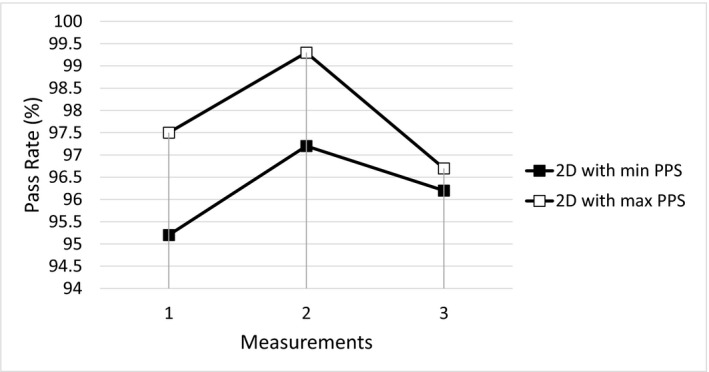
Figure 5 demonstrates the ArcCHECKTM measured passing rate (3%/3 mm criteria and global maximum dose normalization) of each arc in nontracking DCAT and 4D DCAT plans with the maximal and minimal PPS values, and the variation was evaluated based on repeated measurements on three consecutive days. The maximal variation found was 0.5% with respect to 94.6% average passing rate.
Figure 5.

Passing rates of ArcCHECK measurements of each arc in 4D DCAT plans and nontracking DCAT plans.
For 4D DCAT with the maximal PPS, the maximal MLC leaf speed, total leaf travel distance, MLC leaf RMSE, and total beam‐on time were 20 mm/s, 1385 cm, and 157 s, respectively. Compared to 4D DCAT with the minimal PPS, plan with the maximal PPS demonstrated improved motion‐tracking performance including smaller MLC leaf errors (Fig. 6), lower maximal MLC leaf speed, shorter total leaf travel distance, and shorter total beam‐on time (Table 2). The 4D DCAT with the maximal PPS also allowed higher dose rate (298.1 MU/min) for motion tracking. In addition, passing rates of film measurements for 4D DCAT plans with the maximal PPS demonstrated higher passing rates (97.7% ± 1.0%) as shown in Figs. 7 and 8.
Figure 6.
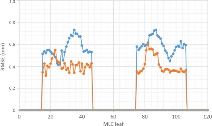
RMSE of MLC leaves (1–120) for 4D DCAT plans. Blue: 4D DCAT with the minimal PPS (0.197). Orange: 4D DCAT with the maximal PPS (0.554). Gray: nontracking DCAT plans (PPS≈1).
Table 2.
Parameters of 4D DCAT plans with the maximal and minimal PPS values
| Parameters | 4D DCAT Plans | |
|---|---|---|
| PPS value | 0.554 | 0.197 |
| Collimator (deg) | 87° | 15° |
| Couch (deg) | 350°(−10°) | 0° |
| Maximum leaf speed (mm/s) | 20 | 25 |
| MLC leaf errors (mm) | 0.39 ± 0.16 | 0.57 ± 0.11 |
| Total beam‐on time (s) | 157 | 239 |
| Total leaf travel distance (cm) | 1385 | 1713 |
| Average dose rate (MU/min) | 298.1 ± 0.4 | 196.1 ± 2.0 |
Figure 7.
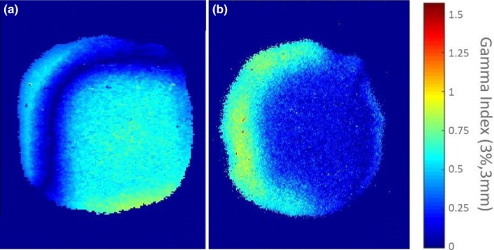
An example of gamma analyses for film measurements of 4D DCAT plans. (a) Passing rates of 4D DCAT plan with the maximal PPS: 99.1%. (b) Passing rates of 4D DCAT plan with the minimal PPS: 97.1%. Failed points are those pixels in the figure with gamma index >1.
Figure 8.
Gamma Passing rates of three repeated film measurements of 4D DCAT plans. Soft square: 4D with the maximal PPS; Solid square: 4D DCAT with the minimal PPS.
Dosimetric differences in Dmin and Dmax to the target between 4D DCAT and nontracking DCAT plans were 0.02 Gy and 0.04 Gy for 4D DCAT with the maximal PPS, and 0.11 Gy and 0.06 Gy for 4D DCAT with the minimal PPS, respectively (Fig. 9 and Table 3). Differences in dosimetric indices to the organs such as spinal cord and lung are also listed in Table 3. There was a minimal difference in heart doses between the two 4D DCAT plans.
Figure 9.
Evaluation of dosimetric effect caused by MLC errors during tracking. Circular: nontracking DCAT plan. Triangular: nontracking DCAT plan with MLC errors from 4D DCAT (PPS = 0.554) delivery; Square: nontracking DCAT plan with MLC errors from 4D DCAT (PPS = 0.197) delivery. Red lines: target. Blue lines: left lung. Green lines: spine. Purple lines: body. Orange lines: heart.
Table 3.
Dosimetric effect of MLC leaf position errors on 4D DCAT plans
| PPS | +∆Dmin (Gy) | +∆Dmax (Gy) | |||
|---|---|---|---|---|---|
| Target | Target | Spinal cord | Body | Lt. lung | |
| 0.554 | −0.02 | −0.04 | 0.00 | 0.00 | 0.00 |
| 0.197 | −0.11 | −0.06 | 0.03 | 0.01 | 0.01 |
+Positive value means the structure dose of a 4D DCAT plan with MLC errors is higher than that of the nontracking DCAT plan.
4. DISCUSSION
Ideally, for a nontracking DCAT plan, when the isocenter is at the target geometric center and the target shape is symmetrical, the target projection to the MLC coordinates at each CP should be identical. In this case, the ideal PPS for nontracking DCAT plans with different collimator and couch angles should be equal to one. In reality, since the target contour generated in the TPS was not a perfect sphere, it resulted in the variation in target projection at each CP (i.e., slight MLC shape variation at each CP). Therefore, PPS results were slightly less than one but also very close to one among different nontracking plans in the study. For the 4D DCAT plans, on the other hand, the PPS values were significantly smaller than one, with a best score of 0.554 in the study. It indicated an increased complexity when carrying out motion tracking using dynamic MLC technique. Compared to the optimization results using 1° gantry angle increment (maximal PPS: 0.554), when using 2° and 5° increments for optimizations, the maximal PPS of 4D DCAT plans were 0.554 and 0.543, respectively. Therefore, similar optimization results can be achieved with higher gantry angle increment (e.g., <5° in this study) which reduces the total optimization time.
The error bars in Fig. 5 show relatively small variation in measurement of delivered plans, which indicates that all plan parameters had been correctly transferred from control console computer to linac for delivery. High passing rates of film measurements and small RMS of MLC leaf position errors verified the accuracy of motion‐tracking simulation algorithm. Compared to 4D DCAT with the minimal PPS, plan with the maximal PPS showed higher average dose rate and less MLC leaf position errors which resulted in faster and more accurate motion tracking. Because of the ideal target shape and motion model, the leaf errors did not significantly affect the passing rates and target dose coverages of 4D DCAT plans with the maximal and minimal PPS. For an irregular shaped tumor with more complicated motion pattern, one would expect the beam aperture difference and target motion between adjacent CPs be larger. Therefore, plan with the minimal PPS will be expected to have more leaf errors during tracking since more leaves will be moving at the maximal speed.
Passing rates of all the film measurements are higher than 90% threshold when using 3%/3 mm criteria, which demonstrates the reliability of the synchronization method using manual beam initiation and cameras for target motion monitoring. Failed points (i.e., yellow and red points) in Fig. 7 indicate motion blurring caused by de‐synchronization during dose delivery.
Using lasers, phantom markers, and digital level for phantom alignment, the measurement setup was of high consistency. Since there is no external control for MLC leaves, motion tracking cannot be interrupted to correct for any discrepancy during delivery. The motion‐tracking accuracy is sensitive to the synchronization between beam initiation and target motion. There are several factors that affect synchronization during 4D DCAT delivery. First, for each 4D DCAT plan delivery, there was a difference in human reaction delay in beam initiation when the target reached to its planned position. Then, linac requires time to reach to the planned dose rate when beam is initiated. Thirdly, with the existence of MLC motor problems and friction between adjacent leaves, some leaves at specific CPs were unable to move at the maximal speed (25 mm/s) to catch up with the target motion. Therefore, linac had to reduce the dose rate in order to move those leaves to the planned position in time. In addition, during tracking, the linac demonstrated higher dose rate instability at lower dose rate level. Because of these effects, MLC leaves were unable to accurately catch the motion as predicted in the tracking simulation. One solution is to reduce the maximal leaf speed limit to a lower level in motion‐tracking algorithm so that MLC leaves can move more smoothly without affecting dose rate. One disadvantage of slowing down leaf speed is that the total delivery time will be longer.
In addition to de‐synchronization, motion‐tracking accuracy is affected by the tracking method for motion perpendicular to the leaf travel direction. Since the MLC leaf width in the central 8 cm field is 2.5 mm, the motion will not be compensated if the amplitude is less than 2.5 mm.
Falk and colleagues28 recently reported on the delivery efficiency of motion‐tracking plan. They pointed out an increased treatment time could potentially increase the risk of systematic drifts of the tumor position. In this study, total beam‐on time of 4D DCAT with the maximal PPS (157 s) was less than the plan with the minimal PPS (239 s), which potentially reduces the possibility of introducing tumor motion variability during delivery.
The main purpose of this study was, by introducing a PPS‐based motion‐tracking algorithm, one can improve the tracking performance of a 4D DCAT plan by optimizing the configuration of collimator and couch angles. All the results demonstrated are based on a phantom with an ideal rigid motion pattern. It is not intended as a report on the improvement of motion management ready for clinical treatment. Based on current work, future studies will involve using optimization algorithm to select the combination of collimator and couch angles for 4D DCAT plans with irregular shaped target and/or actual patient breathing motion.
5. CONCLUSION
In this study, by active selection of collimator angle and couch angle, one can achieve a 4D DCAT plan with the maximal PPS. The 4D DCAT with the maximal PPS demonstrated improved motion‐tracking performance including less MLC leaf position errors, lower maximal MLC leaf speed and shorter beam‐on time. Starting tracking phase has a small impact on the 4D DCAT plan performance.
ACKNOWLEDGMENTS
The authors thank Dr. Daryl Nazareth and Dr. Lalith Kumaraswamy from Roswell Park Cancer Insitute, Buffalo, NY, who provided expertise that greatly assisted the study.
CONFLICT OF INTEREST
None.
Appendix A.
Implementation of MLC Tracking
was the projected motion that is parallel to the MLC leaf travel direction.
| (A1) |
where motion elements in superior, anterior, and right directions are positive; motion elements in inferior, posterior, and left are negative. is the collimator angle, is the couch angle, and is the gantry angle at CP “n” (Fig. Figure A1A1), where n ranged from 0 to 180. is the time segment between adjacent CPs, given by
| (A2) |
where is the MU between two adjacent CPs.
Magnification caused by motion parallel to the beam axis is corrected by the M_factor.
| (A3) |
| (A4) |
where 100 cm is the SAD.
For motion that is perpendicular to the direction of leaf travel, all in‐field MLC leaves will be shifted laterally according to the motion direction by the following equation:
| (A5) |
is the projected motion perpendicular to the MLC leaf travel direction.
| (A6) |
Figure Figure A1.
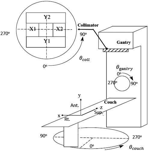
Illustration of room coordinates in motion tracking.
REFERENCES
- 1. Nagata Y, Negoro Y, Aoki T, et al. Clinical outcomes of 3D conformal hypofractionated single high‐dose radiotherapy for one or two lung tumors using a stereotactic body frame. Int J Radiat Oncol Biol Phys. 2002;52:1041–1046. [DOI] [PubMed] [Google Scholar]
- 2. Kavanagh B, Ding MS, Schefter T, Stuhr T, Newman F. The dosimetric effect of inhomogeneity correction in dynamic conformal arc stereotactic body radiation therapy of lung tumors. J Appl Clin Med Phys. 2006;7:58–63. [DOI] [PMC free article] [PubMed] [Google Scholar]
- 3. Bral S, Parijs HV, Soete G, et al. A feasibility study of image‐guided hypofractionated conformal arc therapy for inoperable patients with localized non‐small cell lung cancer. Radiother Oncol. 2007;84:252–256. [DOI] [PubMed] [Google Scholar]
- 4. Matsuo Y, Takayama K, Nagata Y, et al. Interinstitutional variations in planning for stereotactic body radiation therapy for lung cancer. Int J Radiat Oncol Biol Phys. 2007;68:416–425. [DOI] [PubMed] [Google Scholar]
- 5. Piermattei A, Stimato G, Gaudino D, et al. Dynamic conformal arc therapy: Transmitted signal in vivo dosimetry. Med Phys. 2008;35:1830–1839. [DOI] [PubMed] [Google Scholar]
- 6. Takeda A, Sanuki N, Kunieda E, Ohashi T, Oku Y, Takeda T. Stereotactic body radiotherapy for primary lung cancer at a dose of 50 Gy total in five fractions to the periphery of the planning target volume calculated using a superposition algorithm. Int J Radiat Oncol Biol Phys. 2009;73:442–448. [DOI] [PubMed] [Google Scholar]
- 7. Takeda A, Kunieda E, Sanuki N, et al. Dose distribution analysis in stereotactic body radiotherapy using dynamic conformal multiple arc therapy. Int J Radiat Oncol Biol Phys. 2009;74:363–369. [DOI] [PubMed] [Google Scholar]
- 8. Ross CC, Kim JJ, Chen ZJ, et al. A novel modified dynamic conformal arc technique for treatment of peripheral lung tumors using stereotactic body radiation therapy. Pract Radiat Oncol. 2011;1:126–134. [DOI] [PubMed] [Google Scholar]
- 9. Ong CL, Verbakel W, Cuijpers JP, Slotman BJ, Lagerwaard FJ, Senan S. Stereotactic radiotherapy for peripheral lung tumors: A comparison of volumetric modulated arc therapy with 3 other delivery techniques. Radiother Oncol. 2010;97:437–442. [DOI] [PubMed] [Google Scholar]
- 10. Rauschenbach BM, Mackowiak L, Malhotra H. A dosimetric comparison of three‐dimensional conformal radiotherapy, volumetric modulated arc therapy, and dynamic conformal arc therapy in the treatment of non‐small cell lung cancer using stereotactic body radiotherapy. J Appl Clin Med Phys. 2014;15:147–161. [DOI] [PMC free article] [PubMed] [Google Scholar]
- 11. Shi C, Tazi A, Fang DX, Iannuzzi C. Implementation and evaluation of modified dynamic conformal arc (MDCA) technique for lung SBRT patients following RTOG protocols. Med Dosi. 2013;38:287–290. [DOI] [PubMed] [Google Scholar]
- 12. Ouyang L, Lee H, Pompos A, Yan Y, Jiang S, Foster R. Evaluation of flattening‐filter‐free arcs for lung SBRT. Med Phys. 2015;42:3423–3423. [Google Scholar]
- 13. Baumann P, Nyman J, Hoyer M, et al. Outcome in a prospective phase II trial of medically inoperable stage I non–small‐cell lung cancer patients treated with stereotactic body radiotherapy. J Clin Oncol. 2009;27:3290–3296. [DOI] [PubMed] [Google Scholar]
- 14. Chang JY, Balter PA, Dong L, et al. Stereotactic body radiation therapy in centrally and superiorly located stage i or isolated recurrent non–small‐cell lung cancer. Int J Radiat Oncol. 2008;72:967–971. [DOI] [PMC free article] [PubMed] [Google Scholar]
- 15. Fakiris AJ, McGarry RC, Yiannoutsos CT, et al. Stereotactic body radiation therapy for early‐stage non–small‐cell lung carcinoma: Four‐year results of a prospective phase II study. Int J Radiat Oncol. 2009;75:677–682. [DOI] [PubMed] [Google Scholar]
- 16. McGarry RC, Papiez L, Williams M, Whitford T, Timmerman RD. Stereotactic body radiation therapy of early‐stage non–small‐cell lung carcinoma: Phase I study. Int J Radiat Oncol. 2005;63:1010–1015. [DOI] [PubMed] [Google Scholar]
- 17. Nagata Y, Takayama K, Matsuo Y, et al. Clinical outcomes of a phase I/II study of 48 Gy of stereotactic body radiotherapy in 4 fractions for primary lung cancer using a stereotactic body frame. Int J Radiat Oncol. 2005;63:1427–1431. [DOI] [PubMed] [Google Scholar]
- 18. Timmerman R, McGarry R, Yiannoutsos C, et al. Excessive toxicity when treating central tumors in a phase II study of stereotactic body radiation therapy for medically inoperable early‐stage lung cancer. J Clin Oncol. 2006;24:4833–4839. [DOI] [PubMed] [Google Scholar]
- 19. Timmerman R, Paulus R, Galvin J, et al. Stereotactic body radiation therapy for inoperable early stage lung cancer. JAMA. 2010;303:1070–1076. [DOI] [PMC free article] [PubMed] [Google Scholar]
- 20. Li W, Purdie TG, Taremi M, et al. Effect of immobilization and performance status on intrafraction motion for stereotactic lung radiotherapy: Analysis of 133 patients. Int J Radiat Oncol Biol Phys. 2010;81:1568–1575. [DOI] [PubMed] [Google Scholar]
- 21. Seco J, Sharp GC, Wu Z, Gierga D, Buettner F, Paganetti H. Dosimetric impact of motion in free‐breathing and gated lung radiotherapy: A 4D Monte Carlo study of intrafraction and interfraction effects. Med Phys. 2008;35:356–366. [DOI] [PMC free article] [PubMed] [Google Scholar]
- 22. Shimizu S, Shirato H, Ogura S, et al. Detection of lung tumor movement in real‐time tumor‐tracking radiotherapy”. Int J Radiat Oncol Biol Phys. 2001;51:304–310. [DOI] [PubMed] [Google Scholar]
- 23. Erridge SC, Seppenwoolde Y, Muller SH, et al. Portal imaging to assess set‐up errors, tumor motion and tumor shrinkage during conformal radiotherapy of non‐small cell lung cancer. Radiother Oncol. 2003;66:75–85. [DOI] [PubMed] [Google Scholar]
- 24. Ross CS, Hussey DH, Pennington EC, Stanford W, Doornbos JF. Analysis of movement of intrathoracic neoplasms using ultrafast computerized tomography. Int J Radiat Oncol Biol Phys. 1990;18:671–677. [DOI] [PubMed] [Google Scholar]
- 25. Plathow C, Ley S, Fink C, et al. Analysis of intrathoracic tumor mobility during whole breathing cycle by dynamic MRI. Int J Radiat Oncol Biol Phys. 2004;59:952–959. [DOI] [PubMed] [Google Scholar]
- 26. Zhao B, Yang Y, Li T, Li X, Heron DE, Huq MS. Dosimetric effect of intrafraction tumor motion in phase gated lung stereotactic body radiotherapy. Med Phys. 2012;39:6629–6637. [DOI] [PubMed] [Google Scholar]
- 27. Falk M, Rosenschold PM, Keal P, et al. Real‐time dynamic MLC tracking for inversely optimized arc radiotherapy. Radiother Oncol. 2010;94:218–223. [DOI] [PMC free article] [PubMed] [Google Scholar]
- 28. Falk M, Pommer T, Keall P, et al. Motion management during IMAT treatment of mobile lung tumors—A comparison of MLC tracking and gated delivery. Med Phys 2014;41:101707. [DOI] [PMC free article] [PubMed] [Google Scholar]
- 29. Booth JT, Caillet V, Hardcastle N, et al. The first patient treatment of electromagnetic‐guided real time adaptive radiotherapy using MLC tracking for lung SABR. Radiother Oncol. 2016;121:19–25. [DOI] [PubMed] [Google Scholar]
- 30. Sawant A, Venkat R, Srivastava V, et al. Management of three‐dimensional intrafraction motion through real‐time DMLC tracking. Med Phys. 2007;35:2050–2061. [DOI] [PMC free article] [PubMed] [Google Scholar]
- 31. Sun B, Papiez L, Oddiraju S, Yang D, Li H. Target tracking using DMLC for volumetric modulated arc therapy: A simulation study. Med Phys. 2010;37:6116–6124. [DOI] [PMC free article] [PubMed] [Google Scholar]
- 32. McQuaid D, Partridge M, Symonds‐Tayler JR, Evans PM, Webb S. Target tracking deliveries on an Elekta linac: A feasibility study. Phys Med Biol 2009;54:3563–3578. [DOI] [PubMed] [Google Scholar]
- 33. Davies GA, Clowes P, Bedford JL, Evans PM, Webb S, Poludniowski G. An experimental evaluation of the Agility MLC for motion‐compensated VMAT delivery. Phys Med Biol. 2013;58:4643–4657. [DOI] [PubMed] [Google Scholar]
- 34. Davies GA, Clowes P, McQuaid D, Evans PM, Webb S, Poludniowski G. An experimental comparison of conventional two‐bank and novel four‐bank dynamic MLC tracking. Phys Med Biol. 2013;58:1635–1648. [DOI] [PubMed] [Google Scholar]
- 35. Davies GA, Poludniowski G, Webb S. MLC tracking for Elekta VMAT: A modelling study. Phys Med Biol. 2011;56:7541–7554. [DOI] [PubMed] [Google Scholar]
- 36. Yang Y, Zhang P, Happersett L, et al. Choreographing couch and collimator in volumetric modulated arc therapy. Int J Radiat Oncol Biol Phys. 2011;80:1238–1247. [DOI] [PubMed] [Google Scholar]
- 37. Zhang P, Happersett L, Yang Y, Yamada Y, Mageras G, et al. Optimization of collimator trajectory in volumetric modulated arc therapy: Development and evaluation for paraspinal SBRT. Med Phys. 2010;77:591–599. [DOI] [PubMed] [Google Scholar]
- 38. Radiation Therapy Oncology Group . RTOG 0813: Seamless phase I/II study of stereotactic lung radiotherapy (SBRT) for early stage, centrally located, non‐small cell lung cancer (NSCLC) in medically inoperable patients. Philadelphia (PA): RTOG; 2009. [Google Scholar]
- 39. Masi L, Doro R, Favuzzaet V, Cipressi S, Livi L. Impact of plan parameters on the dosimetric accuracy of volumetric modulated arc therapy. Med Phys. 2013;40:071718. [DOI] [PubMed] [Google Scholar]
- 40. Crijns W, Defraene G, Van Herck H, Depuyde T, Haustermans K, Maes F. Online adaptation and verification of VMAT. Med Phys. 2015;42:3877–3891. [DOI] [PubMed] [Google Scholar]
- 41. McGarry CK, Agnew CE, Hussein M, Tsang Y, McWilliam A, Hounsell AR. The role of complexity metrics in a multi‐institutional dosimetry audit of VMAT. Br J Radiol. 1057;2015:20150445. [DOI] [PMC free article] [PubMed] [Google Scholar]