Abstract
Clinical laboratories are recognizing the importance of implementing sensitive and specific molecular diagnostic tests. However, widespread adoption of these tests requires simplified workflows without requiring expensive supporting instrumentation. To enable microarray-based analysis to meet these requirements, we describe a valveless flow cell for disposable use that supports PCR coupled with microarray hybridization in the same chamber. The flow cell assembly consists simply of double-faced tape, a plastic microarray substrate, an absorbent, and a commercially-available hydrophilic thin film. The simple construction lends itself to low-cost and ease of manufacturing, yet several features reduces the complexity of the standard microarray workflow. First, there is no requirement for custom instrumentation. Second, the hydrophilic thin film allows uniform filling of a microfluidic chamber. Third, a geometric capillary stop design confines liquid to the microarray chamber during PCR, and thus eliminates the need for a valve or hydrophobic surface treatment. And fourth, imbibition drives the uniform removal of liquid reagents from the array chamber. Three hundred genomic copies of methicillin-resistant Staphylococcus aureus (MRSA) are detected in a flow cell with gel drop microarrays printed on an unmodified plastic substrate. This sensitivity is shown to be comparable to conventional methods (i.e., PCR in a tube, with separate hybridization in a microarray chamber, where amplicon is exposed to the workspace before and after hybridization). However, the flow cell combines these multiple steps into a simple, compact workflow without the need for complex valves or custom instrumentation and is less susceptible to contamination of the workspace than conventional methods because the amplicon is confined to the device.
Keywords: Microfluidics, microarray, PCR, valveless, imbibition
Introduction
Microfluidic valves are one of the most widely-investigated components of lab-on-a-chip devices because they allow multiple reactions to be processed on a single chip [1]. Confining solutions to reaction chambers are important for a number of reasons. For example, microfluidic valves are used to isolate serial and parallel reactions and enable uniform heat distribution within the solution. They also prevent liquid from flowing in unwanted directions due to the compression and expansion of air bubbles, and they limit the loss of liquid due to imbibition, vaporization, and/or aerosolization. Chemistries that include a washing protocol warrant attention to these considerations when attempting to integrate them into a lab-on-a-chip format.
DNA microarrays, one such chemistry that is used to identify many genetic sequences from a single sample, traditionally include the following steps: polymerase chain reaction (PCR) in a tube, mix the product with a hybridization buffer, transfer the mixture to a square adhesive chamber that contains the microarray slide, apply a cover film to seal the chamber, incubate the chamber, disassemble the chamber assembly, wash the array, rinse with water, dry the slide with air, and analyze the microarray image. This conventional approach can be susceptible to: (1) the introduction of air bubbles when applying a cover film to these square chambers (2) contamination due to the transfer of amplified product to the microarray chamber (3) contamination due to overflow of the amplified product out of the chamber as the cover is applied, and (4) contamination when the chamber is disassembled prior to the washing step. Thus, sealed lab-on-a-chip devices that fill without introducing air bubbles and avoid disassembly, and therefore exposure of liquids (e.g., amplified product), offer the advantage of greatly reducing the risk of contamination compared with conventional methods. However, a shortcoming with many lab-on-a-chip devices is that, although the device is small, the instrumentation is often large and complex. An approach that does not require custom instrumentation, but rather makes use of equipment already present in molecular biology laboratories, offers the potential for wider adoption because there is no need for up front capital investment or technical training for a novel instrument. Additionally, a disposable that can be manufactured at a low cost, requires minimal training, and offers sensitivities that rival conventional techniques increases the likelihood of adoption.
There are many different approaches to microvalves such as those that make use of shape memory alloys, phase changes, pneumatics, and microelectromechanical systems (MEMS). Shape memory alloys are shown to open and close valves by changing shape of a metal such as nitinol in response to heating [2.3]. Phase changes of materials such as hydrogels [4], paraffin [5–6], sol-gels [7], and ice[8,9] from a solid to a liquid are used to open flow paths. Pneumatics are used to deform a compliant membrane and allow reagent flow, and have been most notably used in high density microvalve formats [10]. MEMS are typically fabricated by deep reactive ion etching (DRIE) of semiconductors that can change state in response to electrical excitation, and can be designed to be implantable [11–13]. A thorough review of approaches to valves in microfluidics can be found in the article by Zhang et al. [1]. Whereas these valves all have virtues and niche applications, they require custom instrumentation and/or multi-step manufacturing methods.
Valveless fluidic control is intriguing because it does not require external actuation. One approach to valveless fluidic control is the use of hydrophobic stops, which are abrupt decreases in surface energy used to prevent the advance of a liquid-air interface up to a specified pressure [14–16]. The drawback is that the surfaces must be patterned so that only the region of interest is treated with a hydrophobic coating. This process adds cost to manufacturing because of the fine-featured patterning step and the difficulty to rapidly inspect for quality in a production line to determine whether or not the device meets the desired specifications.
Mark et al. [17] describe a valveless design that does not require multi-step manufacturing. The design is based on contact line pinning to confine reagents to a specific region on a centrifugal microfluidic disk with a positive back pressure arising from the compression of a downstream air pocket, which increases the force required for depinning. The contact line of the advancing front is pinned at the corners of a smaller chamber that opens to a larger chamber until centrifugation forces the liquid beyond the pinned region. Their approach, which uses a specialized instrument, makes use of a commonly-observed pinning effect in horizontally-oriented capillary tubes where the advancing liquid front gets pinned at the capillary tube outlet.
We describe a novel, inexpensive valveless PCR-microarray flow cell that uses a “staircase” geometry in which sequentially smaller channel widths are designed to withstand thermocycling by pinning the advancing contact line to the corners of the reaction chamber. The steps required for a result are to introduce master mix with purified sample into the flow cell, place the flow cell on a conventional slide block thermocycler, wash by pipetting buffer through the flow cell, and image on a conventional microarray imager. This is the first report of a lab-on-a-chip PCR-microarray device that does not require custom instrumentation, eliminates the manufacturing steps required for valves, and confines the amplified product to the device. The top film is hydrophilic to allow capillary action to fill the entire reaction chamber and promote imbibition of the wash solution. We apply this approach to the identification of methicillin resistant Staphyloccocus aureus (MRSA).
Materials and Methods
Flow cell Assembly
Flow cell assemblies, shown in Figure 1, consist of a microarray substrate, a spacer tape, a hydrophilic top film, a waste chamber with an absorbent, an inlet port, and a vent hole. The microarray substrates are either glass (Erie Scientific, Portsmouth, NH) or injection molded using a blend of polyester and polycarbonate plastic (Polylinks, Asheville, NC). Unmodified plastic slides are molded to dimensions of 25.4 mm × 76.2 mm × 1 mm. The flow cells are constructed by laser cutting double-sided tape with cutouts for the inlet channel, reaction chamber, connecting channel, and waste chamber. A top film (Vistex, Thin Film Specialties) covers the array chamber and the waste chamber respectively. An absorbent (Whatman 31 ET CHR chromatography paper) resides in the waste chamber. The top film has a 1 mm hole for the inlet and a 1 mm hole for the vent, which is positioned at the distal edge of the waste chamber. Frame-Seals (BioRad, Hercules, CA) serve as control microarray chambers. The flow cell assemblies and Frame-Seals are prepared at least one hour prior to use.
Figure 1.
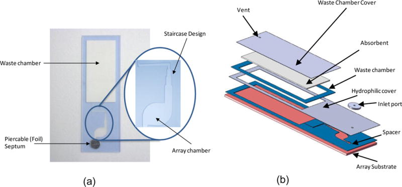
(a) Photograph of the flow cell with a close-up view of the “staircase” design (b) components of the flow cell assembly. The assembly consists of a substrate for the array of gel elements, a spacer tape that provides the fluidic pathway for the reagents, a hydrophilic film that allows the reagents to fill by capillary action, an inlet port that accommodates a pierceable foil tape, and a waste chamber. An additional spacer around the waste chamber accommodates an absorbent that is thicker than the bottom spacer tape in order to allow additional wash volumes.
Microarray and Labeling Method
The microarray consists of a polymer matrix that is printed on blank slides as a gel drop, similar to the methods described elsewhere [18,19], with coordinates that position the array in the reaction chamber of the flow cell once the spacer tape is applied. This printing method consists of a co-polymerization and oligonucleotide probe mixture that is printed on the slide and UV cross-linked. Gel elements are 150 μm in diameter with a 300 μm center-to-center spacing. Probes with target specific sequences are tethered to a polymer backbone at the 3′ end. Nonsense probes (dN20) are twenty-mers with random sequence, used for background correction. Cy3-labeled probes, labeled at the 5′ end with a Cy3 fluorophore, serve as positive controls. Purified target amplification and labeling occurs in an asymmetric PCR master mix containing Cy3-labeled reverse primers in 10-fold excess over unlabeled forward primers. This strategy generates predominantly single-stranded product with a single Cy3 label on their 5′ end. During a final hybridization step, these single stranded products hybridize to their complementary probes, crosslinked in the gel element.
Two microarray designs are investigated. There is a Wound v2.0 array, which has probes for mecA gene, Staphylococcus aureus, Staphylococcus epidermidis, Staphylococcus genus, Staphylococcus saprophyticus, Staphylococcus haemolyticus, Streptococcus genus, Streptococcus pyogenes, and Streptococcus agalactiae. And, there is a MRSA v4.0 array, which has probes for MecA gene, tufA gene, open reading frame: orfX1, Staphylococcus genus, and Staphylococcus aureus.
Sample Preparation
Methicillin-resistant Staphylococcus aureus (MRSA) organisms are obtained in culture form from ATCC and then purified with Akonni’s TruTip (Cat No. 300‐10206). The four-minute TruTip protocol consists of cycling five times up and down with an electronic pipettor for each of the following steps: binding, washing, drying, and eluting. The quantity of DNA is determined with a NanoDrop 3300 Fluorospectrometer (Wilmington, DE).
Frame-Seal Hybridization (PCR is performed in a tube, and hybridization in a Frame-Seal)
A 15 μL master mix is prepared using the Phusion Flash PCR kit (Finnzymes, Finland) and amplified according to the following protocol on a Piko thermocycler (Finnzymes, Finland): 98°C for 10 seconds, 35 cycles of 98°C for 1 sec, 54°C for 10 sec, and 72°C for 10 sec, and a final step of 72°C for 1 minute. A 30 μL reaction, which consists of 20 μL of hybridization mix (containing 1.5 M guanidine thiocyanate, 75 mM HEPES, pH 7.5, 7.5 mM EDTA, 5 mg/mL BSA, and 3.7 fmol/μL hybridization control oligonucleotide) and 10 μL of amplified product, is prepared for addition to the Frame-Seal. The master mix solutions are incubated in a tube for 5 minutes at 95°C to denature double stranded DNA prior to the hybridization protocol. Of this 30 μL, 28 μl is added to the Frame- Seal chamber and covered with Parafilm. All the slides are placed on the MJ Research PTC-200 DNA Engine thermocycler with attached alpha unit slide tower and hybridized for three hours at 55°C.
On-Chip Hybridization (PCR is performed in a tube, and hybridization in a flow cell)
A 15 μL reaction volume, which consists of 10 μL of hybridization master mix (see the subsection Frame Seal Hybridization) and 5μL of amplified product (see the subsection Frame-Seal Hybridization), is prepared for addition to the flow cell. The sample inlet port is covered with silicone tape that was laser cut into a 6.35 mm diameter circle and the waste chamber vent is left open. The master mix solutions are incubated in a tube for 5 minutes at 95°C to denature double stranded DNA prior to the hybridization protocol.
On-Chip PCR (PCR and hybridization performed in the flow cell)
On-chip PCR in this context refers to a single step protocol that consists of solution phase PCR in the reaction chamber followed by hybridization to the microarray. A 15 μL master mix is prepared containing final concentrations of 1X PCR buffer (HotstarTaq Plus, Qiagen), 2 mM MgCl2, 1.2 mg/mL BSA, 200 μM dNTPs, 10% (w/v) formamide, 2.4U Taq DNA Polymerase, and 0.03-1 μM of each primer set. The sample inlet port is covered with a pierceable foil adhesive and the waste chamber vent is left open to reduce the operational burden of having to remove the vent. All the slides are placed on the MJ Research PTC-225 DNA Engine thermocycler with alpha unit slide tower and samples are amplified and hybridized with the following thermocycling protocol: 86.5°C for 2 min, and 35 cycles of 86.5°C for 45 sec, 50°C for 1 min 30 sec, and final steps of 65°C for 5 min, 85°C for 2 min and 40°C for 45 min.
Washing
Frame-Seals
The Frame-Seals are removed and the slides are washed for 3 minutes in a Telechem ArrayIt™ Brand High Throughput Wash Station containing 250 mL of 1X SSPE and 0.01% Triton X-100, rinsed in two separate 250 mL baths of water, and dried with filtered, compressed air.
Flow cells
After hybridization or on-chip amplification, the foil tape covering the sample inlet port is pierced with a pipettor and the array is washed with volumes of 1X SSPE that range from 35 to 200μL. In some cases the wash step is followed by pipetting 25μL of water to mimic the water rinse performed on frame seals, and then 15 μL or 75 μL of acetone into the flow cell. To ensure the acetone is completely removed from the array chamber, the flow cell is inverted for 3 minutes to allow residual acetone to drain into the waste chamber. (The flow cells are thoroughly dried using this acetone procedure to be compatible with an Aurora PortArray 5000). All the materials including the plastic substrate, described in the flow cell assembly section, are found to be compatible with this acetone wash procedure, which reduces the time of the heat drying step. The slides are then dried on a custom heat block, designed for a ThermoFisher 2001FSQ digital controlled heater, for 15 minutes at 50°C. This drying procedure is referred to as an “on-chip drying protocol” because the flow cell is not disassembled as opposed to the Frame-Seal protocol, which requires the removal of adhesives prior to washing and air drying.
Detection and Analysis
The arrays are imaged using either an Aurora PortArray 5000, GenePix 4000B or Akonni’s DX2000 microarray imager. The Akonni DX2000 uses an oblique angle laser-illumination technique and a non-cooled CCD camera for detection. Unbinned output (12-bit, offset=0, gain=1) from all imagers are saved in 16-bit, grayscale, tagged image file format (TIFF), Revision 6.0 standard [20]. The .tif images are analyzed using the Spotfinder open-source application (Windows version 3.1.1, “Spotfinder3.1.1.exe”) from The Institute for Genomic Research [21]. Image segmentation is performed with the Otsu thresholding algorithm [22] within Spotfinder, and (median) background-corrected integral intensities for all spots are saved along with other derived statistics, related quality indices, and array location indicators, in a tab-delimited flat file (.mev) format. Subsequent data analysis is performed with Microsoft Office Excel 2003 Service Pack 3, where the average integral intensity of the replicate spots for each probe is compared to either the standard deviation of the background or the average intensity of spots containing the dN20 nonsense oligonucleotide (a model for biological noise due to nonspecific hybridization events).
Results and discussion
Flow cells are constructed using the design shown in Figure 1 to evaluate the following features: a geometric “staircase” as a means of liquid confinement during stringent temperature conditions such as thermocycling, the inclusion of a hydrophilic surface as a means of uniformly filling reaction chambers, and the addition of an absorbent to the waste chamber in order to imbibe wash solutions. The utility and functionality of these flow cell features are evaluated by comparing the fluorescence of gel drop microarrays following PCR and hybridization to that of conventional microarray protocols.
Figure 2 shows comparable microarray images for the following three cases: PCR in a tube followed by hybridization in the flow cell, simultaneous PCR and hybridization in the flow cell, and PCR in a tube followed by hybridization in a Frame-Seal. For the second case (simultaneous PCR and hybridization in the flow cell) the liquid remains confined to the reaction chamber throughout thermocycling. The protocols are performed as described in the materials and methods section with wash buffer volumes of 175 μL of 1X SSPE, 25 μL of water, and 15 μL of acetone for both the on-chip amplification and the flow cell hybridization. The amplification master mix does not contain hybridization markers, and thus the hybridization spots in Figure 2b do not fluoresce.
Figure 2.
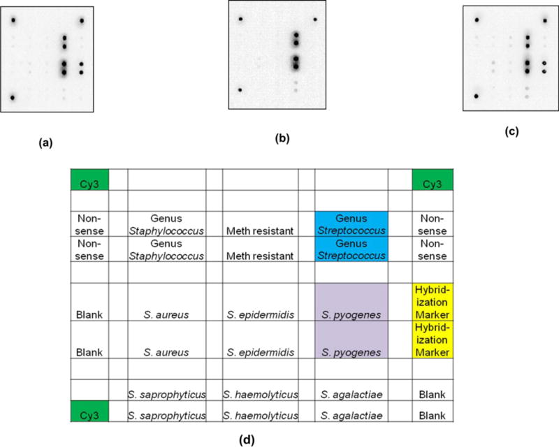
Inverse images of Wound v2.0 arrays challenged with 104 genomic copies of S. pyogenes under the following conditions (a) amplification in a tube, hybridization in a flow cell, washing with a pipettor, on-chip drying, and imaging of the intact flow cell (b) PCR amplification in a flow cell, washing with a pipettor, on-chip drying, and imaging of an intact flow cell (c) amplification in a tube, hybridization on the array in a Frame Seal, removal of the Frame Seal, washing in a bath and air drying. (d) Array map corresponding to images where dN20 corresponds to nonsense probes. Note the hybridization markers are only visible in images (a) and (c) because the on-chip amplification in (b) does not have hybridization markers in the master mix.
Figure 3 shows the signal-to-noise ratio of S. pyogenes and Staphylococcus genus in replicates of 3 for each condition with error bars that represent minimum and maximum values. The starting genomic copy number for each condition is approximately 104. Additional studies over a wide dynamic range and various hybridization conditions are necessary to thoroughly compare the three conditions. However, this data suggests that the on-chip amplification for the flow cell gives comparable performance to amplification in a tube followed by transfer to the flow cell as well as amplification in a tube followed by transfer to a Frame-Seal.
Figure 3.
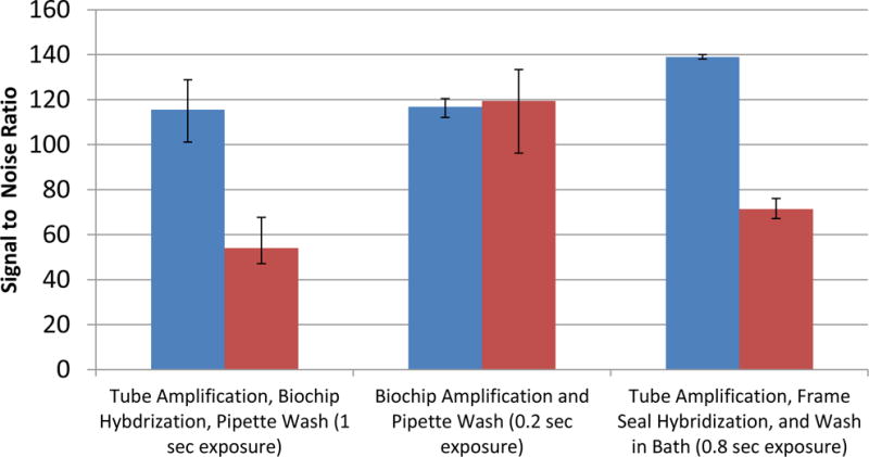
Microarray signal comparison between the flow cell and Frame-seal methods using the Wound v2.0 array according to the following conditions: 1) tube amplification and hybridization in the flow cell followed by a pipet wash and on-chip drying protocol, 2) flow cell amplification followed by a pipet wash and on-chip drying protocol, and 3) tube amplification followed by Frame-Seal hybridization, washing in a bath and air drying. In each case 104 genomic copies of S. pyogenes is amplified (n=3). The integral spot intensity minus the local background of two targets spots divided by the standard deviation of the background are used to calculate the signal to noise ratios shown. Using an Aurora Port Array 5000, the images are acquired for exposure times up to the duration when the spots are just below saturation.
The approach of imbibing wash solutions into the waste chamber from the reaction chamber are evaluated by comparing nonsense signals from gel drop microarrays following PCR and hybridization using conventional protocols with those in the flow cell. Figure 4 shows this comparison following complete imbibition of all observable liquid from the reaction chamber. The data indicates that the flow cell imbibitions washing approach was superior to conventional washing in a microarray bath. It is noteworthy, that 100 μL of wash solution in the flow cell outperformed 250 mL of wash solution used for the frame seal method. In addition, the frame seal required compressed air to achieve sufficient drying of the array for imaging while the flow cell did not.
Figure 4.
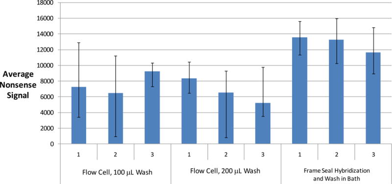
Comparison of dN20 nonsense signals after different washing conditions using the Wound v2.0 array. Six flow cells with a pipettor using two different volumes of 1X SSPE and 25 μL of water versus the gold standard of hybridizing in Frame-Seals and washing arrays in a 1X SSPE microarray bath followed by a water rinse. The flow cells undergo an on-chip amplification procedure whereas the Frame Seals are used only for hybridization using amplified product from a standard PCR tube. The Frame Seals are subsequently removed in order to directly expose the array to the wash buffers in the bath, a water rinse, and air drying. The flow cells are dried per the protocol described in the experimental section and imaged with an Aurora Port Array 5000 for 0.2 seconds. The input sample is 104 genomic copies of S. pyogenes for both the flow cells and the Frame Seals. The nonsense spots are identified with Spotfinder, and the integral fluorescent intensity of each of 4 nonsense spots minus the local background is averaged and plotted along with error bars, which represent the minimum and maximum values. The nonsense signals are inversely proportional to the effectiveness of washing because the dN20 nonsense probes fluoresce due to non-specific binding with labeled product.
The behavior of gel-drop microarrays printed directly on an injection-molded non-functionalized plastic substrate as part of the flow cell assembly is also evaluated as a low-cost alternative to glass. The fluidic behavior of filling, contact line pinning at the “staircase”, and imbibition for the plastic-substrate flow cells show the same behavior compared with the glass substrate. Figure 5 shows the resulting image using a GenePix 4000B of an MRSA array printed on a plastic flow cell following on-chip amplification. For this experiment, 105 copies of isolated genomic MRSA are combined with a PCR master mix and introduced into the plastic flow cell. This result shows good reproducibility across all four array quadrants with no visual evidence of dN20 nonsense signals or hybridization markers, which are not used in our PCR flow cell protocol. Note, some probes exhibit stronger signal intensity than others because of differences in sequence length and thermodynamics. The protocol used for this test consists of a duplex assay with primers for the mecA and tufA genes, thus, as expected, only the corresponding probes are observed (the spots in the purple circles are probes for mecA and the spots in the blue and orange circles are probes for the tufA gene). The flow cell for this study is washed by pipetting 35 μL of 1X SSPE through the inlet hole, across the array, and into the absorbent in the waste chamber, which imbibes all observable liquid from the reaction chamber. The water pipetting step and the acetone drying step were eliminated for this study to explore the possibility of reducing the number of post-PCR pipetting steps to just one.
Figure 5.
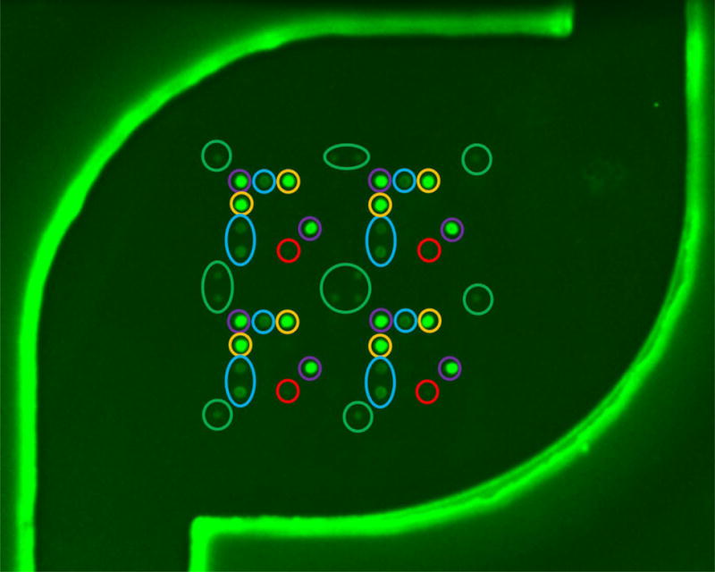
Image of an MRSA v4.0 array through the film of a completely-intact plastic flow cell following on-chip amplification of 105 genomic copies of MRSA using PCR primers for mecA and tufA. The flow cell was washed with 35μl of 1X SSPE without implementing a drying protocol, and imaged for 0.5 sec with a GenePix 4000B. Colored circles correspond to different probes: Green, positive control Cy3 labeled oligos; purple, mecA gene, which confers methicillin resistance; blue, tufA gene found in S. Aureus strains; orange, tufA gene found in all Staph strains; red, nonsense spots that serve as a control for washing.
Results of a limit of detection study using plastic-substrate flow cells and imaging on the Akonni imager are shown in Figure 6. The detection limit found in these studies is approximately 300 copies (1 pg of MRSA) using our duplex mecA and tufA assay. The wash protocol to obtain these results consists of 35 μL of 1XSSPE, 25 μL of water, 75μL of acetone, and heating for 15 minutes at 50°C. Although liquid removal from the microarray by imbibition increases the fluorescence emission of the microarray spots, additional improvement is observed with the implementation of an acetone drying step. This signal improvement suggests that some liquid remains bounds to the gel elements, despite that the chamber appears to be devoid of liquid. Thus, the acetone drying step, which does not require disassembly of the flow cell, offers a method of removing liquid from the highly hydrophilic gel elements without any observable adverse effects. The improvement ranges from about 2 to 3 times. In general, the results suggest comparable performance between the on-chip amplification in the flow cell and the standard tube amplification with the Frame-Seal hybridization method, yet the flow cell does not require disassembly of the array chamber, negating the risk of amplicon exposure. Whereas typical protocols involving separate amplification and microarray hybridization require upwards of 6-7 hours, we demonstrate simultaneous amplification and hybridization in 2 hours and 45 minutes.
Figure 6.
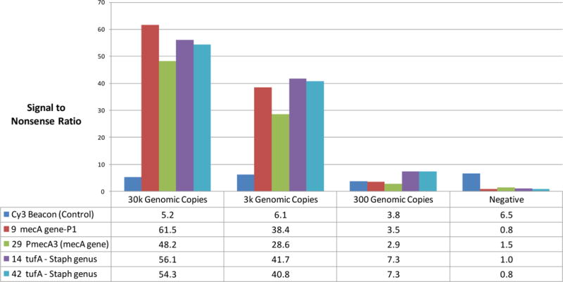
Limit of detection study using the MRSA v4.0 array along with on-chip amplification and pipet washing and drying protocol with intact plastic flow cells. Signal-to-nonsense ratios greater than 3 are considered positive. Nonsense signals indicate the level of biological noise due to nonspecific hybridization events. Images are acquired with Akonni’s Dx2000 reader, and ratios are determined with the use of Spotfinder, which calculates the integral spot intensity minus the local background of the targets spots and nonsense spots.
There are several advantages to our flow cell design that allow for proper control of fluids, which is important for molecular detection on a microarray. Pinning the advancing contact line of the liquid front serves as a means of confining the master mix to the reaction chamber of these flow cells during thermocycling. This approach to liquid confinement reduces the manufacturing burden of lab-on-a-chip devices because it does not require additional assembly steps and it can be visually inspected for quality. Furthermore, the flow cells do not require specialized instrumentation as supported by the use of a conventional thermocycler, pipettor for washing, and imaging with three different microarray imagers. Another benefit of this device is that the arrays can be washed without exposing liquids, such as amplified product, to the workspace. Additionally, the use of a hydrophilic top film allows complete and uniform filling of the chamber as opposed to the characteristic air pockets that frequently form along the edges when filling conventional hydrophobic plastic chambers.
The flow cell channel, designed as a symmetrical “staircase” (Figure 1a) that decreases in channel width away from the reaction chamber towards the waste chamber, serves two purposes. First, it results in a sequential increase in capillary pressure promoting imbibition once wetted with wash buffer. And second, the “staircase” design serves to pin the contact line of the advancing liquid front during thermocycling, which eliminates the need for a valve. In the absence of this “staircase”, we observe that at elevated temperatures, the liquid advances along the edges of the channel and establishes a fluidic path with the absorbent, prior to the completion of the thermocycling protocol. Once a fluidic path is established with the absorbent, the absorbent facilitates continuous imbibition of the reaction buffer from the reaction chamber. The implementation of 90° corners that comprise the “staircase”, on the other hand, pin the contact line of the meniscus. This phenomenon can be compared to that observed by Schaffer and Wong [23] in which vertically-oriented capillary tubes show decreased travel distance in tubes with rough interior surfaces compared to smooth surfaces due to contact line pinning in the crevices of the rough surface. We observe the staircase design to be effective up to approximately 90°C. Thus, our assays were designed to have a lower denaturing temperature than 95°C as described elsewhere [24].
Our hypothesis for the complete and uniform filling of the reaction chambers is that the capillary pressure of the advancing front is higher at the wall than the center of the array chamber due to the presence of the hydrophilic top film. This increased capillary pressure is due to the smaller radius of curvature of the meniscus when approaching the corner, according to the Young-Laplace equation:
where ∆P is the pressure difference across the meniscus interface, γ is the surface tension, and R1 and R2 are the principle radii of curvature of the meniscus. This relationship predicts chamber filling along the edges and corners prior to the bulk in the absence of pressure-driven flow [25,26], which supports our observations. In the case of pressure-driven flow, generated by the pipettor, we hypothesize that the capillary forces dominate, and thus the chambers fill without introducing air bubbles. In fact, we find that square reaction chambers with a hydrophilic top film also fill uniformly with pipet flow without introducing air bubbles or air pockets (design and data not shown). The reason that the reaction chamber has rounded edges in the design of Figure 1 is that the liquid does not consistently imbibe into the absorbent during the wash step when using the square design.
An additional benefit of the hydrophilic top film is the uniform evacuation of liquid. Typically, draining liquid from plastic microfluidic devices can be very challenging because air bubbles attach to the hydrophobic plastic surfaces and trap liquid drops. Low-energy surfaces, such as hydrophobic plastics, are not preferentially wetted, and thus, create a more favorable condition for air bubbles to attach to the walls. Dislodging air bubbles from hydrophobic plastics, hence, requires sufficient force to wet the low energy surface, such as achieved with centrifugation. In general, aqueous solutions wet high energy surfaces, establishing a thin liquid film that promotes downstream bubble migration by inertia or gravity [27]. Thus, we do not observe residual liquid drops being trapped in the reaction chamber as a result of the top hydrophilic film.
Conclusion
We demonstrate a geometric microfluidic design that can serve as a valve for lab-on-a-chip devices, especially those that include a PCR step. The valveless flow cell device described here confines liquid to a reaction chamber while undergoing thermocycling until additional wash buffer advances the reagent to the waste chamber. This approach, which includes amplification in the same reaction chamber as the microarray, is demonstrated at 300 copies of bacterial DNA without needing disassembly or specialized instrumentation. These flow cells consist of injection-molded plastic substrates, thin films, absorbents, and double-faced tape, making them amenable to low cost manufacturing.
Acknowledgments
The authors wish to thank partial support from the National Institutes of Health (grant no. 1 RO1 AI59517) and the National Institute of Justice (award no. 2007-DN-BX-K145) for supporting some of the development of the flow cell design. The authors also wish to acknowledge the helpful insights gained from attendance at Math-in-Industry Workshop, Claremont Colleges 2009.
References
- 1.Zhang C, Xing D. Nucleic Acids Res. 2007;35:4223. doi: 10.1093/nar/gkm389. [DOI] [PMC free article] [PubMed] [Google Scholar]
- 2.Kohl M, Dittmann D, Quandt E, Winzek B. Sens Actuators A. 2000;83:214. [Google Scholar]
- 3.Pemble CM, Towe BC. Sens Actuators A. 1999;77:145. [Google Scholar]
- 4.Wang J, Chen ZY, Mauk M, Hong KS, Li MY, Yang S, et al. Biomed Microdevices. 2005;7:313. doi: 10.1007/s10544-005-6073-z. [DOI] [PubMed] [Google Scholar]
- 5.Pal R, Yang M, Johnson BN, Burke DT, Burns MA. Anal Chem. 2004;76:3740. doi: 10.1021/ac0352934. [DOI] [PubMed] [Google Scholar]
- 6.Liu RH, Yang J, Lenigk R, Bonanno J, Grodzinski P. Anal Chem. 2004;76:1824. doi: 10.1021/ac0353029. [DOI] [PubMed] [Google Scholar]
- 7.Liu Y, Rauch CB, Stevens RL, Lenigk R, Yang J, Rhine DB, et al. Anal Chem. 2002;74:3063. doi: 10.1021/ac020094q. [DOI] [PubMed] [Google Scholar]
- 8.Sgro AE, Allen PB, Chiu DT. Anal Chem. 2007;79:4845. doi: 10.1021/ac062458a. [DOI] [PMC free article] [PubMed] [Google Scholar]
- 9.Chen Z, Wang J, Qian S, Bau HH. Lab Chip. 2005;5:1277. doi: 10.1039/b508275g. [DOI] [PubMed] [Google Scholar]
- 10.Thorsen T, Maerkl SJ, Quake SR. Science. 2002;298:580. doi: 10.1126/science.1076996. [DOI] [PubMed] [Google Scholar]
- 11.Yang X, Grosjean C, Tai Y-C, Ho C-M. Proc. IEEE (MEMS ’ 97); Japan. 1997. p. 114. [Google Scholar]
- 12.Henning AK. Aerospace Conference. Proc IEEE; Colorado. 1998. p. 471. [Google Scholar]
- 13.Richards Grayson AC, Shawgo RS, Johnson AM, Flynn NT, Li Y, Cima MJ, Langer R. Proc IEEE. 2004;92 [Google Scholar]
- 14.Feng Y, Zhou Z, Ye X, Xiong J. Sens Actuators A. 2003;138:108. [Google Scholar]
- 15.Burns M, Johnson B, Brahmasandra S, Handique K. Science. 1998;282:484. doi: 10.1126/science.282.5388.484. [DOI] [PubMed] [Google Scholar]
- 16.Madou M, Lee L, Daunert S, Lai S, Shih C. Biomed Microdevices. 2001;3:245. [Google Scholar]
- 17.Mark D, Metz T, Haeberle S, Lutz S, Ducr J, Zengerleab R, von Stettenab F. Lab Chip. 2009;9:3599. doi: 10.1039/b914415c. [DOI] [PubMed] [Google Scholar]
- 18.Vasiliskov AV, Timofeev EN, Surzhikov SA, Drobyshev AL, Shick VV, Mirzabekov AD. Biotechniques. 1999;27:592. doi: 10.2144/99273rr06. [DOI] [PubMed] [Google Scholar]
- 19.Rubina A, Dementieva EI, Stomakhin AA, Darii EL, Pan’kov SV, Barsky VE, Ivanov SM, Konovalova EV, Mirzabekov AD. Biotechniques. 2003;34:1008. doi: 10.2144/03345rr01. [DOI] [PubMed] [Google Scholar]
- 20.TIFF Revision 6.0. (1992).
- 21.Saeed A, et al. Biotechniques. 2003;34:374. doi: 10.2144/03342mt01. [DOI] [PubMed] [Google Scholar]
- 22.Liao TP, Chung P. JISE. 2001;17:713. [Google Scholar]
- 23.Schäffer E, Wong P. Phys Rev Lett. 1998;80:3069. [Google Scholar]
- 24.Castley A, Higgins M, Ivey J, Mamotte C, Sayer DC, Christiansen FT. Clin Chem. 2005;51:2025. doi: 10.1373/clinchem.2005.055327. [DOI] [PubMed] [Google Scholar]
- 25.Dong M, Chatzis I. J Colloid Interface Sci. 1995;172:278. doi: 10.1016/j.jcis.2003.11.052. [DOI] [PubMed] [Google Scholar]
- 26.Weislogel M, Lichter S. J, Fluid Mech. 1998;373:349. [Google Scholar]
- 27.Wenzel RN. Ind Eng Chem. 1938;28:988. [Google Scholar]


