Abstract
The push to advance efficient, renewable, and clean energy sources has brought with it an effort to generate materials that are capable of storing hydrogen. Metal-organic framework materials (MOFs) have been the focus of many such studies as they are categorized for their large internal surface areas. We have addressed one of the major shortcomings of MOFs (their processibility) by creating and 3D printing a composite of acrylonitrile butadiene styrene (ABS) and MOF-5, a prototypical MOF, which is often used to benchmark H2 uptake capacity of other MOFs. The ABS-MOF-5 composites can be printed at MOF-5 compositions of 10% and below. Other physical and mechanical properties of the polymer (glass transition temperature, stress and strain at the breaking point, and Young’s modulus) either remain unchanged or show some degree of hardening due to the interaction between the polymer and the MOF. We do observe some MOF-5 degradation through the blending process, likely due to the ambient humidity through the purification and solvent casting steps. Even with this degradation, the MOF still retains some of its ability to uptake H2, seen in the ability of the composite to uptake more H2 than the pure polymer. The experiments and results described here represent a significant first step toward 3D printing MOF-5-based materials for H2 storage.
Introduction
Hydrogen is attractive as a fuel for transportation because of its high energy density and its potential to be produced renewably.[1] In one scheme for generating H2, solar energy is used to convert water into H2. Through combustion, this H2 will produce energy and be converted back into water. Tangential to developing these technologies are requirements for advanced H2 storage materials. A number of approaches to H2 storage have emerged in response to this need.[1] Storing H2 as a liquid is one option. Unfortunately, liquid hydrogen requires cryogenic temperatures, which are impractical. The low density of liquid hydrogen would necessitate larger fuel tanks on automobiles. Any storage material would need to overcome these bottlenecks.
One of the major efforts within the research community is to develop metal-organic framework materials (MOFs) for H2 storage.[2-5] MOFs are three-dimensional coordination polymers in which the interactions between a metal ion and multidentate organic molecules lead to production of empty cavities as part of the crystallographic unit. The cavities within MOF structures are noted for their ability to adsorb gases. It has been shown that some MOFs allow for gas storage at higher densities than can be reached in compressed gas cylinders.[6]
MOF-5 is a coordination polymer built around zinc ions and benzodicarboxylate ions and has the formula unit Zn4O(BDC)3.[4] MOF-5 was one of the first MOFs whose H2 storage capacity pointed to the potential for MOF gas storage, in general. MOF-5 was chosen for this study because it is a prototypical MOF material,[4] is easy to synthesize in large quantities[7], and its gas storage capacities have been well characterized.[8]
While many are hopeful that MOFs will play a role in meeting gas storage needs, there are several limitations to the practical use of MOFs. Primary among these is MOF processibility. That is, generating usable objects from MOF powders has thus far been difficult. Current efforts to address this problem include growing larger crystals,[9] growing MOFs off of a solid substrate,[10-14] and incorporating MOFs into polymer films and spheres.[15-25]
With the issue of processibility in mind, we have set out to produce polymer-MOF composite materials that could be formed, molded, or extruded into any number of shapes. While films are appropriate for some applications, other applications, which include those that need high flow rates, require more complicated geometries. To push these boundaries of structured MOF composites, we produced an acrylonitrile-butadiene-styrene (ABS) MOF-5 composite that can be printed with a conventional thermoplastic 3D printer.
We have produced ABS-MOF-5 composites and successfully 3D printed these materials into a number of geometries (Figure 1). ABS is one of the most commonly used materials in thermoplastic 3D printing. We have characterized the chemical, thermophysical, and mechanical properties of the composite materials. Importantly, we measured the H2-uptake and release properties of the printed ABS-MOF-5 composite at room temperature, which is more appropriate for any useful device than the low temperature measurements normally used to assess material internal surface area. While further system optimization is needed, our results show great promise for generating 3D printable polymer-MOF composites for hydrogen storage.
Figure 1. ABS-MOF-5 filament and printed objects.
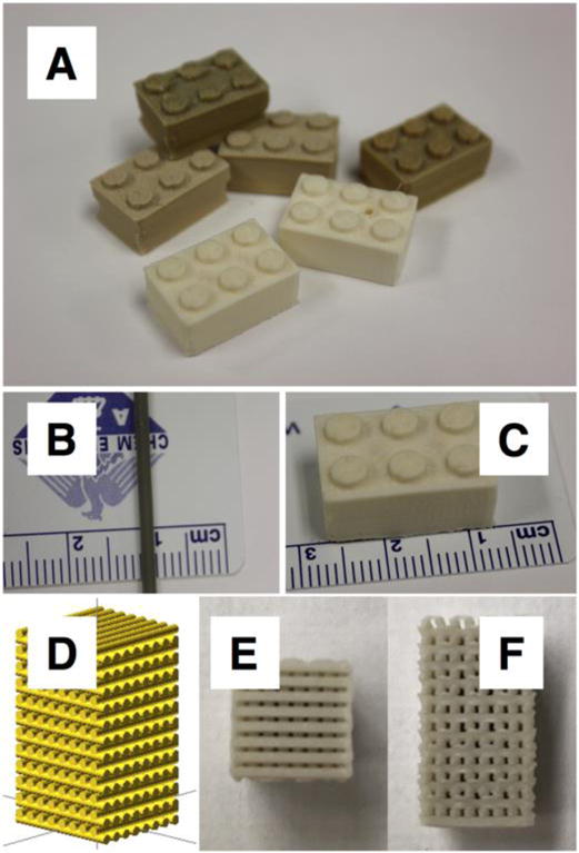
(A) 3D printed blocks produced with 1%, 5%, and 10% MOF-5 composites. (B) 1.75 mm diameter filament used in the printing process. (C) 3D printed block showing scale. (D) Image rendering of object designed to be comprised of 0.8 mm diameter cylinders. (E and F) Top and side view of the 3D printed object described in panel D.
Materials and Methods[27]
Zinc acetate dihydrate was purchased from Baker Chemical. Benzene-1,4-dicarboxylic acid was purchased from Sigma Aldrich. Triethylamine (TEA) and N,N-dimethylforma-mide (DMF) were purchased from EMD Millipore. Acetone was purchased from BDH chemicals. Acrylonitrile butadiene styrene (ABS) pellets (Resin: GPA 100, Color #: NC010, Color: Natural, Lot #: C14-0702K) were acquired from LTL Color Compounders, Inc.
MOF-5 Synthesis
MOF-5 was synthesized at room temperature according to a literature protocol as described below.[7] Approximately 5 g of benzene-1,4-dicarboxylic acid and 8.5 mL of TEA were dissolved in 400 mL of DMF. In a separate flask, approximately 17 g of zinc acetate dihydrate was dissolved in 500 mL of DMF with stirring. These two mixtures were combined and MOF-5 formation proceeded over 2.5 hours. After the end of this time, the suspension was divided among Thermo Scientific polypropylene 750 mL Bio-Bottle tubes and centrifuged with a Sorvall RC 6+ centrifuge for 1 hour at 4000 rpm. The white paste was collected and isolated with vacuum filtration. During the filtration process, the product was washed with DMF.
Solvent Casting ABS and MOF-5
ABS and MOF-5 were suspended and solvent cast using a previously described protocol.[26] Briefly, a total of 50 g of solid material were placed in a flask with 500 mL of acetone. The total amount of MOF-5 and ABS were altered to achieve different MOF-5 content. The suspension was sonicated using a VWR Symphony sonicator until the ABS had dissolved. The suspension was poured into a Tef-lon coated frying pan and placed on a hot plate set to 60 °C until and a film had formed and no solvent was visible.
Extrusion and Filament Formation
The film was cut into squares and extruded with a DSM Xplore Micro 15 cc Twin Screw Compounder (conical screws, rotating at 80 revolutions per minute, temperature in all heating zones set to 195 °C, extruded through a 3 mm die). The filaments produced in this first step were not the correct size to be used by the 3D printer. These initial filaments were cut into smaller pieces and formed into 1.75 mm-wide filaments using a Filabot Wee Extruder set to 195 °C.
3D Printing
The filaments were printed into multiple shapes using a Flashforge Creator 3D Printer with Dual Extruders. Structures were printed with a layer height of 100 μm at a speed of 10 mm/s onto a heated platform. The printing nozzle was set to 230 °C and the platform to 115 °C. These settings are necessary to ensure a smooth printing process without clogging the printer heads for producing printed structures that don’t peel off of the print bed as the extruded polymer cools and contracts. For all printed pieces, the infill was set to 100%. The dog bone objects used for mechanical testing were printed with a horizontal geometry using a criss-cross (45°/-45°) pattern with a 100% infill.
Powder X-ray Diffraction
X-ray diffraction data were collected with a Rigaku Miniflex II, which employed a 450 W Cu K α (λ = 0.1540462 nm) X-ray source, an NaI scintillation counter detector, and a diffracted beam monochrometer. The samples, pieces of solvent-cast film, were mounted on aluminum holders.
Differential Scanning Calorimetry (DSC)
DSC data were recorded using a TA Instruments DSC Q2000. For each measurement, around 3 mg of composite was placed in an aluminum Tzero pan and sealed with a hermetic lid (both the pan and the lid were obtained from TA Instruments). Samples were a) heated from 20 °C to 170 °C with the temperature increasing by 40 °C/minute; b) held at 170 °C for 2 minutes; c) cooled from 170 °C to 110 °C with the temperature decreasing by 40 °C/minute; d) held at 110 °C for °60 minutes (to drive off any remaining solvent); e) cooled from 110 °C to 20 °C with the temperature decreasing by 40 °C/minute; and f) held at 20 °C for 2 minutes. Steps (a), (b), (c), (e), and (f) were repeated twice.
Mechanical Testing
Dog bone structures, with a shape defined by the American Society for Testing and Materials (standard D638), were printed for ABS, ABS-1% MOF-5, ABS-5% MOF-5, and ABS-10% MOF-5. The tensile properties of these dog bone structures were analyzed using a Mark 10, Series 5 Universal Testing Machine using a travelling speed of 1.2 inches per minute. Five samples of each composite were printed and tested.
Scanning Electron Microscope (SEM) and Energy Dispersive X-ray Spectroscopy (EDS)
Images and EDS maps of the ABS-10% MOF sample were acquired using an FEI Helios NanoLab 660 Dual Beam Scanning Electron Microscope. SEM images were recorded at a voltage of 15.00 kV and a dwell time of 10 μs. EDS was used to evaluate the presence and location of carbon and zinc in the samples.
H2 Adsorption and Desorption Measurements
The full experimental details for the H2 adsorption and desorption measurements are given in the Supporting Information. Briefly, samples for the desorption measurement were prepared by incubating a degassed (3 days at 103 °C under vacuum), 3D printed structure for 28 hours at a H2 pressure of 60.7 kPa. The chamber was quickly evacuated and the H2 pressure was measured as a function of time. For the adsorption measurement, a 3D printed sample was degassed and exposed to 60.7 kPa of H2 for two minutes, after which the pressure in the chamber was measured as a function of time. The moles of H2 adsorbed or desorbed were calculated from the pressure change.
Results and Discussion
We produced a range of composites with different MOF-5 mass percentages. With increasing mass percentage, we found that the solvent-cast films became increasingly heterogeneous, with clumps of MOF-5 distributed less evenly within the ABS. Because of this phase separation, we focused on making 3D printing filaments for the composites that contained up to 10% MOF-5. Figure 2 shows an SEM image and EDS map of the cross-section of a printed object using the ABS-10% MOF-5 composite. The SEM shows crystals amid an amorphous polymer. The EDS confirms that the zinc is located within the crystals, as would be expected for MOF-5.
Figure 2. SEM and EDS analysis of a cross section of an object printed with ABS-10% MOF-5.
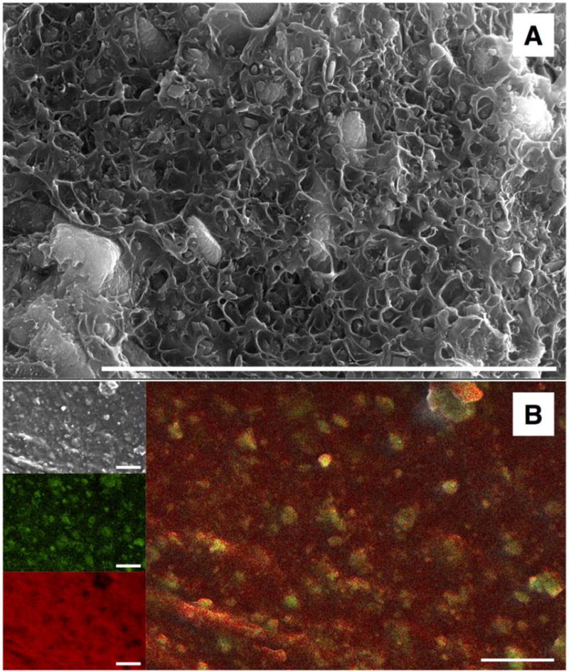
Scale bar: 10 μm. Panel A: SEM image showing the inorganic crystal within an amorphous polymer matrix. Panel B: (top left) SEM image, (middle left) EDS measured location of zinc atoms, (bottom left) EDS measured location of carbon atoms, (right) overlay of zinc and carbon location maps.
We measured the glass transition temperature (Tg) for the ABS-MOF-5 composite filaments at different weight percentages. Tg is especially relevant for our composite materials as this phase transition is critical for the ability of the polymer to print. The full results are shown in the supporting information (Figures S2-S4) and are summarized in Table 1. The data show that the MOF-5 content has no real effect on Tg. This observation is in contrast with our observations for TiO2 composites in which we found that the TiO2, and not the thermal processing, affected the glass transition temperature of the composite.[26] The result indicates that any interaction between the polymer and the MOF does not significantly affect the polymer-polymer interaction.
Table 1.
Thermal and mechanical properties of ABS-MOF-5 composites
| Glass Transition Temperature (°C) | Average values at breaking point
|
Young’s Modulus (MPa) | ||
|---|---|---|---|---|
| Stress (MPA) | Strain (%) | |||
| ABS | 106 | 39 ± 4 | 10 ± 1 | 5.2 ± 0.4 |
| 1% MOF-5 | 106 | 49 ± 4 | 12 ± 2 | 6.5 ± 0.7 |
| 5% MOF-5 | 105 | 39 ± 1 | 14 ± 2 | 4.0 ± 0.5 |
| 10% MOF-5 | 105 | 48 ± 1 | 11 ± 1 | 6.2 ± 0.4 |
| 20% MOF-5 | 105 | Composites at these percentages were unable to print structures for testing | ||
| 30% MOF-5 | 106 | |||
| 40% MOF-5 | 106 | |||
| 50% MOF-5 | 105 | |||
We were able to generate 3D printing filaments with ABS, 1% ABS, 5% ABS, and 10% ABS. These filaments were produced for use within a commercially available 3D printer. It was important for us that any techniques we use be immediately scalable and adoptable. For instance, the compounding method that we employed is used by industry on a larger scale and is specifically used to produce the colored filaments that are currently used in 3D printers. Additionally, we wanted to use the same type of 3D printers most used by hobbyists in their own homes. As we continue to develop this technology, our aim is to optimize implementation.
Using the ABS-MOF-5 filaments, we printed dog bone structures to test the composite’s mechanical properties. In general, it appears as though the MOF-5 strengthens the composite in comparison to the pure polymer. That is, the stress at the breaking point increases from pure ABS for the 1% and 10% MOF-5 composites. As the gas uptake capacities of these materials, and not their mechanical properties, were the primary focus of this study we did not address it further in the experiments presented here.
Figure 3 shows the powder X-ray diffraction (XRD) data for the ABS-10% MOF-5 composite, ABS, and different forms of MOF-5. We find that the MOF-5 within our composite shows a similar scattering pattern to a form that has been degraded by humidity.[28] XRD patterns for the other composites (1%, 5%, 20%, 30%, and 50%) are found in the supporting information (Figure S1) and also show incorporation of degraded MOF-5.
Figure 3. XRD spectra of the ABS-10% MOF-5 composite.
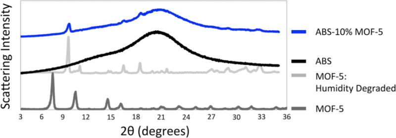
Dark gray: spectrum for MOF-5 in its powdered form. Light gray: spectrum for humidity degraded MOF-5. Black: spectrum for ABS. Blue: spectrum for ABS-10% MOF-5 composite. The composite spectrum shows several scattering peaks (8.9, 15.7, 17.8, 28.6, and 33.9 degrees) that match with the humidity degraded MOF-5 sample.
We expect that there are two likely steps where ambient humidity may have played a role in altering the MOF-5 structure. The building where material production was carried out often experiences ambient humidity levels above 70% relative humidity. A previous study showed that MOF-5 degradation becomes measurable when exposed to 50% relative humidity for 24 hours.[28] In our protocols, the most likely step where humidity plays a role was the filtering process during the MOF-5 synthesis. A slurry of MOF-5 and chloroform (or DMF) was filtered through a 0.45 μm-pore filter. This process was time consuming and was often allowed to proceed over 24 hours. There were multiple filtering steps for each batch synthesized. The ambient humidity in the building could have affected the stability of the MOF-5. Another possibility could have been that the MOF-5 degraded during solvent casting. While process took, on average, around an hour, there is lower likelihood for the decomposition to have occurred during this step. A final step where humidity may play a role is during the compounding step, where ABS and MOF-5 are blended together at 195 °C. However, we expect that once MOF-5 is incorporated into the polymer (after the solvent casting step), the MOF will be less susceptible to ambient humidity. In support of this assertion, we have previously determined that water was adsorbed by 3D printed ABS at a capacity of 0.35% w/w.[29] Similarly, Cohen and coworkers have shown that MOFs within a polymer matrix are less susceptible to humid conditions.[17, 20]
While we are working with a degraded form of MOF-5 in our composites, further measurements of H2 uptake by our 3D printed objects remain valuable. That is, in this proof-of-concept material, it must be determined if the MOF still accessible within the polymer matrix. Previous research has shown that even the degraded MOF-5 structures maintain some ability to uptake H2.[28] So, although the absolute capacity of MOF-5 may be somewhat diminished, showing that it retains its ability to adsorb H2 within the 3D printed composite is a necessary measurement for showing the potential for any H2 storage by a 3D printed MOF structure. With this in mind, we set out to determine if the compromised MOF-5 structures in our printed ABS-MOF-5 objects would retain their ability to adsorb gas molecules.
We tested the ability of MOF-5 to function within the ABS matrix after 3D printing (Figure 4 and Table 2). Specifically, we measured the material’s capacity to adsorb H2. For this study, we compared the properties of the ABS-10% MOF-5 composite with that of pure ABS. Previous studies have shown the ability of MOFs to adsorb gas molecules while incorporated into a composite film.[15-20] The results, presented here, show that the degraded MOF-5 within our composite retains its capacity to adsorb gas molecules in a more complex polymer environment.
Figure 4.
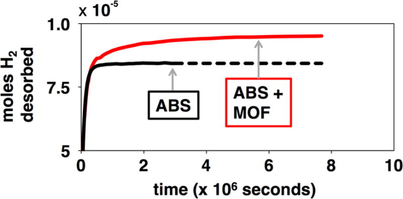
H2 desorption from ABS (black) and ABS-10% MOF-5 (red).
Table 2.
H2 capacity of printed composites
|
|
||
|---|---|---|
| ABS | ABS-10% MOF-5 | |
| g of H2 per g of composite | 2.64 × 10⁻⁶ | 2.97 × 10⁻⁶ |
|
| ||
| g of H2 specifically bound to MOF-5 per g of MOF 5 within the composite | – | 5.90 × 10⁻⁶ |
Our observations for ABS-10% MOF-5 H2 adsorption can be contextualized by prior research. First, the measured H2 capacity per gram of printed material is 1.15 times greater for the ABS-10% MOF-5 composite than pure ABS (Table 2). Further, the specific H2 capacity is found to be 6.1 × 10⁻⁴ mass % of H2 at 60.7 kPa and 23 °C by the MOF within the ABS. This value is comparable to the absolute adsorption of H2 by pure MOF-5 at room temperature and similar H2 pressure (1.6 × 10⁻³ mass % H2, estimated from reference 3).[3] By this estimation, we retain 33% of the theoretical MOF-5 H2 capacity for the structurally degraded MOF-5 within our composite. Another study looked at the H2 adsorption and surface area properties of MOF-5 that had been degraded by humidity.[28] In these experiments, the surface area and adsorption were recorded at 77 K and 10,000 kPa H2. The authors’ findings are qualitatively similar to our observations. Specifically, they observe that the humidity degraded MOF-5 has a surface area that is 40% that of the pristine MOF-5 sample (BET surface areas of 1000 m2/g and 2500 m2/g, respectively). They also observe that the H2 adsorption capacity drops by over half when the MOF is degraded. Their measurement of excess adsorption capacity shows 5 g of H2 per g of MOF-5 (for the pristine sample) and under 2.5 g of H2 per g of MOF-5 (for the humidity damaged sample).
Our finding shows that H2 will still be adsorbed by MOF-5 within a 3D printed ABS composite and that it shows no further degradation from humidity once the composite has been formed. Both of these conclusions are crucial for demonstrating the applicability of our approach.
To further analyze the ability of MOF-5 within the ABS composite to bind H2, the kinetics of H2 uptake and release were evaluated (Figures 5 and Table S1 in supporting information). In pure ABS, H2 exhibits a multi-exponential diffusion through the printed object with rates on the order of 10−3 s−1 and 10−4 s−1. Adsorption of H2 by the ABS-10% MOF-5 composite has a similar profile to that of pure ABS; the only difference between ABS and ABS-10% MOF-5 coming from an absolute difference in H2 storage capacity. This observation is consistent with a model in which both the polymer and the MOF are involved in H2 storage within the composite. It is also consistent with the ABS limiting the rate at which H2 diffuses through the composite. H2 desorption from the ABS-10% MOF-5 composite displays a different profile than H2 adsorption (Figure 5 and Table S1). Specifically, H2 desorption from ABS-10% MOF-5 is slower than adsorption of H2. We observe a slower rate component (1×10⁻⁵ s−1) in the fitting of the data for the desorption of H2 from ABS-10% MOF-5. This slow component accounts for nearly 20% of the decay data, which roughly corresponds to the percentage of H2 bound specifically to MOF-5 within the composite. This result is consistent for the case where H2 has a specific adsorption to the material of interest. That is, because H2 has a strong interaction with the MOF-5, the rate of diffusion out of MOF-5 is slower than its diffusion through ABS.
Figure 5.
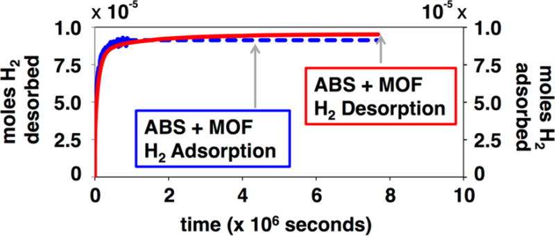
H2 adsorption (blue) and desorption (red) by ABS-10% MOF-5.
Taken together, these data signal the potential for 3D printing of polymer-MOF composite materials. Importantly, our research indicates that environmental molecules can access MOFs at the interior of the printed material. The current study shows, specifically, that MOF-5 retains its capacity to store H2 in 3D printed objects. This conclusion is corroborated by our previous study with printed ABS-TiO2 composites where molecules in aqueous solution could access nanoparticles within a printed structure.[26] For applications that involve chemical storage, this property is crucial because it shows that storage can be optimized by increasing the content of MOF content of the composite. That H2 storage is possible for MOF-5 within the interior of the printed composite is indicative that our composites are different from materials that incorporate MOFs by synthesizing them on the outside of some preformed, or printed, substrate.[10-14] Future studies in which MOFs are incorporated into 3D printing polymers in their non-degraded states will feature a more complete analysis of the interior pore structure found in the composite materials.
The capacity to process MOFs into any possible geometry could lead to a number of new devices that take advantage of different MOF properties (gas adsorption and catalysis, among others). Efforts are certainly required to optimize these systems. In our study, for example, the measurements were made at room temperature (MOF gas storage increases with decreasing temperature) using a generic 3D printed structure that had not been designed for gas permeation and storage. Further, covalently incorporating the MOFs onto a polymer may increase the weight percentage of MOFs within a printable composite.[19, 20]
While we do observe some MOF-5 degradation through the incorporation process, we have identified areas where we can better maintain its structural integrity. Specifically, we contend that replacing the filtration steps with filtration in atmospherically controlled environments, such as a glove box, or with isolating material with centrifugation will maintain the MOF-5 structure. Another possibility is to remove the solvent casting step and directly blend the MOF-5 powder with ABS. Importantly, though, we do show that the MOF is not further degraded once it is incorporated into the polymer. As there is other evidence that casting MOFs within polymer films increases their resistance to degradation in humid environments,[17] we expect that our 3D printed ABS-MOF-5 composites will show similar stabilities.
Conclusions
The research presented here is an important first step towards designing and 3D printing H2 storage devices. The potential geometries available to 3D printed materials coupled to the various different MOF structures lead to a number of possibilities for optimizing any printed device. Our study will contribute to these future efforts by showing that MOFs can easily be incorporated into 3D printing polymers while maintaining their functionality.
Supplementary Material
Acknowledgments
The authors would like to thank Matthew Skorski of American University for assistance in the 3D printing process. The authors would like to thank Professor Douglas Fox of American University for the use of the twin-screw compounding instrument.
Footnotes
Supporting Information. The Supporting Information contains a more complete description of materials and methods, X-ray diffraction data, DSC data, mechanical testing data, description of the H2 adsorption and desorption measurements along with kinetic fitting for these measurements.
No competing financial interests have been declared.
References
- 1.Liu C, Li F, Ma LP, Cheng HM. Adv Mat. 2010;22:E28. doi: 10.1002/adma.200903328. [DOI] [PubMed] [Google Scholar]
- 2.Murray LJ, Dinca M, Long JR. Chem Soc Rev. 2009;38:1294. doi: 10.1039/b802256a. [DOI] [PubMed] [Google Scholar]
- 3.Panella B, Hirscher M. Adv Mat. 2005;17:538. [Google Scholar]
- 4.Rosi NL, Eckert J, Eddaoudi M, Vodak DT, Kim J, O’Keeffe M, Yaghi OM. Science. 2003;300:1127. doi: 10.1126/science.1083440. [DOI] [PubMed] [Google Scholar]
- 5.Sculley J, Yuan DQ, Zhou HC. Energy & Environmental Science. 2011;4:2721. [Google Scholar]
- 6.Alezi D, Belmabkhout Y, Suyetin M, Bhatt PM, Weselinski LJ, Solovyeva V, Adil K, Spanopoulos I, Trikalitis PN, Emwas AH, Eddaoudi M. J Am Chem Soc. 2015;137:13308. doi: 10.1021/jacs.5b07053. [DOI] [PMC free article] [PubMed] [Google Scholar]
- 7.Tranchemontagne DJ, Hunt JR, Yaghi OM. Tetrahedron. 2008;64:8553. [Google Scholar]
- 8.Zhou W, Wu H, Hartman MR, Yildirim T. J Phys Chem C. 2007;111:16131. [Google Scholar]
- 9.Li LN, Sun FX, Jia JT, Borjigin T, Zhu GS. Crystengcomm. 2013;15:4094. [Google Scholar]
- 10.Kreno LE, Hupp JT, Van Duyne RP. Anal Chem. 2010;82:8042. doi: 10.1021/ac102127p. [DOI] [PubMed] [Google Scholar]
- 11.Zhou JJ, Wang P, Wang CX, Goh YT, Fang Z, Messersmith PB, Duan HW. ACS Nano. 2015;9:6951. doi: 10.1021/acsnano.5b01138. [DOI] [PMC free article] [PubMed] [Google Scholar]
- 12.Li LM, Jiao XL, Chen DR, Lotsch BV, Li C. Chem Mater. 2015;27:7601. [Google Scholar]
- 13.Liu JX, Redel E, Walheim S, Wang ZB, Oberst V, Liu JX, Heissler S, Welle A, Moosmann M, Scherer T, Bruns M, Gliemann H, Woll C. Chem Mater. 2015;27:1991. [Google Scholar]
- 14.Wang Z, Wang J, Li M, Sun K, Liu C-j. Sci Rep. 2014;4:5939. doi: 10.1038/srep05939. [DOI] [PMC free article] [PubMed] [Google Scholar]
- 15.Zornoza B, Tellez C, Coronas J, Gascon J, Kapteijn F. Micropor Mesopor Mat. 2013;166:67. [Google Scholar]
- 16.Seoane B, Coronas J, Gascon I, Benavides ME, Karvan O, Caro J, Kapteijn F, Gascon J. Chem Soc Rev. 2015;44:2421. doi: 10.1039/c4cs00437j. [DOI] [PMC free article] [PubMed] [Google Scholar]
- 17.DeCoste JB, Denny MS, Peterson GW, Mahle JJ, Cohen SM. Chem Sci. 2016;7:2711. doi: 10.1039/c5sc04368a. [DOI] [PMC free article] [PubMed] [Google Scholar]
- 18.Denny MS, Cohen SM. Angew Chem Int Edit. 2015;54:9029. doi: 10.1002/anie.201504077. [DOI] [PubMed] [Google Scholar]
- 19.Zhang ZJ, Nguyen HTH, Miller SA, Cohen SM. Angew Chem Int Edit. 2015;54:6152. doi: 10.1002/anie.201502733. [DOI] [PubMed] [Google Scholar]
- 20.Zhang ZJ, Nguyen HTH, Miller SA, Ploskonka AM, DeCoste JB, Cohen SM. J Am Chem Soc. 2016;138:920. doi: 10.1021/jacs.5b11034. [DOI] [PubMed] [Google Scholar]
- 21.Zhu QL, Xu Q. Chem Soc Rev. 2014;43:5468. doi: 10.1039/c3cs60472a. [DOI] [PubMed] [Google Scholar]
- 22.Li S, Huo F. Nanoscale. 2015;7:7482. doi: 10.1039/c5nr00518c. [DOI] [PubMed] [Google Scholar]
- 23.Ling RJ, Ge L, Diao H, Rudolph V, Zhu ZH. ACS Applied Materials & Interfaces. 2016;8:32041. doi: 10.1021/acsami.6b11074. [DOI] [PubMed] [Google Scholar]
- 24.Huo J, Marcello M, Garai A, Bradshaw D. Adv Mat. 2013;25:2717. doi: 10.1002/adma.201204913. [DOI] [PubMed] [Google Scholar]
- 25.Kubica P, Wolinska-Grabczyk A, Grabiec E, Libera M, Wojtyniak M, Czajkowska S, Domanski M. Micropor Mesopor Mat. 2016;235:120. [Google Scholar]
- 26.Skorski MR, Esenther JM, Ahmed Z, Miller AE, Hartings MR. Sci Tech Adv Mater. 2016;17:89. doi: 10.1080/14686996.2016.1152879. [DOI] [PMC free article] [PubMed] [Google Scholar]
- 27.Certain equipment and materials are identified in this paper in order to specify the experimental procedure adequately. Such identification is not intended to imply endorsement by the National Institute of Standards and Technology, nor is it intended to imply that the materials or equipment identified are necessarily the best available.
- 28.Ming Y, Purewal J, Yang J, Xu CC, Soltis R, Warner J, Veenstra M, Gaab M, Muller U, Siegel DJ. Langmuir. 2015;31:4988. doi: 10.1021/acs.langmuir.5b00833. [DOI] [PubMed] [Google Scholar]
- 29.Sefa M, Ahmed Z, Fedchak JA, Scherschligt J, Klimov N. Journal of Vacuum Science & Technology A. 2016;34:061603. doi: 10.1116/1.4965304. [DOI] [PMC free article] [PubMed] [Google Scholar]
Associated Data
This section collects any data citations, data availability statements, or supplementary materials included in this article.


