Abstract
Spiral MRI sequences were developed for a 9.4T vertical standard bore (54 mm) superconducting magnet using unshielded and self-shielded gradient coils. Clear spiral images with 64-shot scan were obtained with the self-shielded gradient coil, but severe shading artifacts were observed for the spiral-scan images acquired with the unshielded gradient coil. This shading artifact was successfully corrected with a phase-correction technique using reference scans that we developed based on eddy current field measurements. We therefore concluded that spiral imaging sequences can be installed even for unshielded gradient coils if phase corrections are performed using the reference scans.
Keywords: spiral scan, shielded gradient coil, superconducting magnet, eddy current
Introduction
Spiral MRI sequences have several unique advantages over other MRI sequences, such as efficient data acquisition, flexible k-trajectory design, robustness to flow and motion, and short echo times.1,2 However, there are many hurdles to be overcome such as very high magnetic field homogeneity, precise gradient waveform design and control, and image reconstruction, and many studies have dealt with spiral MRI since its original demonstration.3–7
Recently, we reported on echo-planar imaging (EPI) using an unshielded gradient coil set for a 9.4T standard vertical bore (54 mm) superconducting magnet.8 In this previous study, the unshielded gradient coil was used to obtain a sufficient sample volume (32 mm diameter bore of the gradient coil) designed for live mouse imaging in the small bore magnet, and the eddy current problems for EPI were overcome by gradient rise-time control and phase corrections using reference scans. Spiral imaging sequences are very sensitive to eddy current fields similar to the EPI sequences, and therefore development of spiral imaging sequences using an unshielded gradient coil in a superconducting magnet is also challenging. To the author’s knowledge, there have been no studies that have reported spiral imaging using an unshielded gradient coil in a superconducting magnet to date.
In this study, we developed a phase correction technique for spiral-scan images based on eddy current measurements and reference scans, and we successfully obtained spiral-scan images with the unshielded gradient coil that were as clear as those acquired with the self-shielded gradient coil.
Materials and Methods
MRI system using a 9.4T vertical-bore superconducting magnet
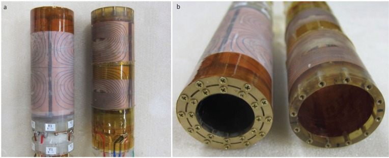
The MRI system consisted of a 9.4T vertical-bore superconducting magnet, a home-built room-temperature shim coil, two exchangeable gradient coil sets, a radio-frequency (RF) coil, and a digital MRI console. The superconducting magnet (JMTC-400/54/SS, JASTEC, Kobe, Japan) had a 54 mm diameter room-temperature bore and the homogeneity was about 1 ppm over 17 mm in diameter and 36 mm long central ellipsoidal volume. The room-temperature shim coil consisted of five second-order coil elements wound over an acrylic pipe (outer diameter [o.d.] = 44 mm, inner diameter [i.d.] = 40 mm) using 0.4 mm diameter polyurethane coated Cu wire. We used both unshielded and self-shielded exchangeable gradient coil sets (MRTechnology Inc., Tskukuba, Japan) as shown in Fig. 1. For the unshielded gradient coil, the o.d. and i.d. were 39 and 32 mm, and the efficiencies were 19.0, 19.2, and 33.7 mT/m/A for Gx, Gy, and Gz, respectively. For the self-shielded gradient coil, the o.d. and i.d. were 39 and 24 mm and the efficiencies were 23.3, 24.1, and 26.6 mT/m/A for Gx, Gy, and Gz, respectively. The RF coil was a home-built saddle-shaped coil (14 mm diameter and 22 mm long). The MRI system was controlled by a digital MRI console with a 128-bit word length and 1 μs time-resolution pulse sequence controller.9
Fig. 1.
Self-shielded and unshielded gradient coils for the 9.4T vertical bore superconducting magnet. (a) Side view, self-shielded (left) and unshielded (right). (b) Top view, self-shielded (left) and unshielded (right). The bore diameters are 32 and 24 mm for the unshielded and self-shielded gradient coils, respectively.
Configuration of metallic conductors affecting eddy currents in the magnet
The cryostat of the 9.4T standard bore superconducting magnet was composed of three copper tubes and one aluminum tube. The copper tubes were used for the room temperature bore and cryogen vessels, and their temperatures were room temperature, liquid nitrogen temperature (77 K), and liquid helium temperature (4.2 K). The inner diameters of the copper tubes were 53.84, 61.14, and 69.74 mm, and their lengths were 971, 797, and 684 mm, respectively. The thickness of all the copper tubes was 1.63 mm. The aluminum tube was used for a bobbin for the superconducting wire. The inner diameter, length, and thickness of the aluminum tube were 81.1, 410, and 3.0 mm, respectively.
The gradient coil sets had a few tens of micrometer thick cylindrical copper RF shields just inside the bore. The saddle shaped RF coil had another cylindrical copper RF shield. The outer diameter, length, and thickness of the RF shield were 22, 78, and 0.1 mm, respectively.
Measurements of eddy current magnetic fields generated by the gradient coils
When time-varying electric currents are flowing through gradient coils, eddy currents are induced in the surrounding conducting parts in the magnet. The eddy currents produce eddy current magnetic fields that vary with time. The eddy current magnetic fields consist of various spatial components with different spatial symmetries usually represented by spherical harmonic functions. Among the spatial components of the eddy current magnetic fields, the dominant ones are the spatially uniform components called “B0 eddy fields” and the spatially linearly changing components called “linear eddy fields.”10
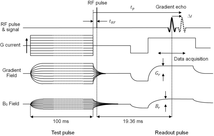
To measure the B0 eddy and the linear eddy fields, we placed a water phantom made of a plastic sphere (o.d. = 10 mm, i.d. = 8 mm) filled with CuSO4 water solution at the center of the gradient coils in the magnet and used the pulse sequence shown in Fig. 2. In this pulse sequence, a gradient pulse with 100 ms duration time was applied at the beginning, and a square RF pulse (pulse width = 24 μs) was applied after a delay time tRF from the falling edge of the gradient pulse. The free induction decay (FID) signal was affected by the linear eddy and the B0 eddy fields as shown in Fig. 2. The effects of the eddy fields were detected using the gradient echo signal observed 19.36 ms after the application of the RF pulse. The gradient echo signal was repeatedly acquired as the gradient coil current was changed from −5.000 to +4.844 A in 64 steps. The linear eddy fields were calculated from the positional shift Δt of the gradient echo peak, and the B0 eddy fields were calculated from the phase shift of the gradient echo peak. The linear eddy and the B0 eddy fields measured as the functions of tRF, which was changed from 0.01 to 100 ms by 52 steps, were decomposed into three exponentially decaying components with different time constants and different amplitudes.
Fig. 2.
Pulse sequence to measure the linear eddy fields and the B0 eddy fields. Gr and Br are amplitudes of the readout field gradient and applied homogeneous field. The current of the gradient coil was changed from −5.00 A to +4.844 A in 64 steps. The time tRF was changed from 0.01 to 100 ms by 52 steps. RF, radio-frequency.
Pulse sequence design and the image reconstruction method
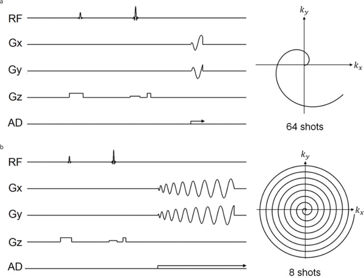
The spiral gradient waveforms were designed using the analytical solution developed by Glover.3 The image matrix was 128 × 128 pixels, and the number of shots was 2, 4, 8, 16, 32, and 64; the data acquisition times for the one shot scan were 75.58, 37.79, 19.14, 9.57, 4.79, and 2.39 ms, respectively. The slice thickness was 2 mm, and the FOV was 15.36 mm × 15.36 mm. Because TR of one-shot spiral data acquisition was 400 ms, the total data acquisition times were 0.8, 1.6, 3.2, 6.4, 12.8, and 25.6 s for 2-, 4-, 8-, 16-, 32-, and 64-shot spiral sequences, respectively. The pulse sequences and k-trajectories developed for 64- and 8-shot spiral data acquisition are shown in Fig. 3. We used a water phantom made of 19 glass capillaries (o.d. = 1.4 mm, i.d. = 0.9 mm, length = 120 mm) in an nuclear magnetic resonance (NMR) sample tube (o.d. = 10.0 mm, i.d. = 9.0 mm, length = 130 mm) filled with CuSO4 doped water solution (T1 ∼ 200 ms).
Fig. 3.
Pulse sequences and k-trajectories for the multishot spiral imaging sequences. (a) 64 shots. (b) 8 shots. Only one trajectory is displayed in the k-space. RF, radio-frequency.
For comparison, we used a two dimensional (2D) spin-echo Fourier imaging sequence with TR = 400 ms, TE = 80 ms, data-acquisition window = 64 ms, image matrix = 256 × 256, slice thickness = 2 mm, and FOV = 15.36 mm × 15.36 mm, and one-shot 2D EPI sequences using Gx and Gy readout gradients with TR = 400 ms, TE = 80 ms, data-acquisition window = 64 ms, image matrix = 64 × 64, slice thickness = 2 mm, and FOV = 15.36 mm × 15.36 mm. These images were measured using the unshielded gradient coil.
Image reconstruction was performed using the 2D Fourier transform after nearest neighbor gridding and convolution gridding methods using a Gaussian convolution kernel.2,11
Phase correction using the reference scan
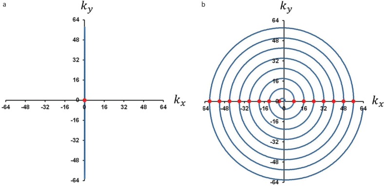
To measure phase shifts of the NMR signal caused by the eddy current fields, we acquired the NMR signal using the spiral imaging sequences with Gx or Gy switched off. In these reference scans, the k-trajectories oscillated on the kx or ky axes and repeatedly passed through the k-space origin (Fig. 4). Therefore, large NMR signal peaks were repeatedly observed when the k-trajectory passed through the k-space origin. We detected the peak positions and calculated the phase of the NMR signals at the peak positions observed at the k-space origin.
Fig. 4.
(a) The k-trajectory of the reference scan for one of the 8-shot spiral scan with Gx OFF and Gy ON. At the center of the k-space, large echo signals are repeatedly observed; (b) k-trajectory for one of the 8-shot spiral scan. The echo peaks observed in (a) correspond to the positions marked as the circles on the kx axis.
Results
Eddy current magnetic fields measured for the gradient coils
Tables 1 and 2 show time constants and relative amplitudes, the ratio of the amplitude of the linear eddy fields to that of applied gradient fields, of two major exponentially decaying components of the linear eddy fields measured for the unshielded and the self-shielded gradient coils. In Table 1, the components of the linear eddy fields for the unshielded gradient coil are categorized into two groups: one group with time constants of about 0.3 ms and relative amplitudes of 25–38% and another with time constants of about 7 ms and relative amplitudes of 7–11%. In Table 2, the components of the linear eddy fields for the shielded gradient coil are categorized into major two groups: one group with time constants of about 0.05 ms (50 μs) and relative amplitudes of about 60% and another with time constants of about 0.3–0.45 ms and relative amplitudes of 1.1–2.4%. The amplitude of the linear eddy field components with time constants of about 0.3 ms reduced from 25–38% to 1.1–2.4% from the unshielded to the self-shielded gradient coil, clearly demonstrating that the linear eddy fields were drastically reduced from the unshielded to the self-shielded gradient coil.
Table 1.
Time constants and relative amplitudes of the linear eddy fields observed for the unshielded gradient coils. The relative amplitude is the ratio of the amplitude of the linear eddy fields to that of applied gradient field
| Gx | Gy | Gz | ||||
|---|---|---|---|---|---|---|
| Component 1 | Component 2 | Component 1 | Component 2 | Component 1 | Component 2 | |
| Time constant [ms] | 0.27 | 6.6 | 0.28 | 6.8 | 0.26 | 7.0 |
| Relative amplitude [%] | 38.4 | 10.7 | 30.1 | 8.90 | 24.9 | 6.99 |
Table 2.
Time constants and amplitudes of the linear eddy fields observed for the self-shielded gradient coils. The relative amplitude is the ratio of the amplitude of the linear eddy fields to that of applied gradient field
| Gx | Gy | Gz | ||||
|---|---|---|---|---|---|---|
| Component 1 | Component 2 | Component 1 | Component 2 | Component 1 | Component 2 | |
| Time constant [ms] | 0.053 | 0.29 | 0.054 | 0.46 | 0.048 | 0.30 |
| Relative amplitude [%] | 61.0 | 1.62 | 56.4 | 1.09 | 61.4 | 2.39 |
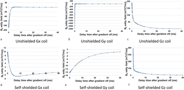
Tables 3 and 4 show the time constants and amplitudes of two major exponentially decaying components of the B0 eddy fields measured for the unshielded and the self-shielded gradient coils. The B0 eddy fields were normalized by those produced by the gradient switching of 1 T/m/s. The temporal changes of the B0 eddy fields measured for the unshielded and self-shielded gradient coils are shown in Fig. 5. It is remarkable that the unshielded Gy gradient coil induced a large B0 field with a very short time constant (∼84 μs).
Table 3.
B0 eddy field measured for the unshielded gradient coil. The amplitude is normalized by the amplitude for the gradient field switching of 1 T/m/s
| Gx | Gy | Gz | ||||
|---|---|---|---|---|---|---|
| Component 1 | Component 2 | Component 1 | Component 2 | Component 1 | Component 2 | |
| Time constant [ms] | 0.84 | 11.6 | 0.084 | 12.6 | 0.048 | 7.26 |
| Amplitude [μT/(T/m)] | 183 | −7.4 | −1766 | 7.68 | 128 | 65.8 |
Table 4.
B0 eddy field measured for the self-shielded gradient coil. The amplitude is normalized by the amplitude for the gradient field switching of 1 T/m/s
| Gx | Gy | Gz | ||||
|---|---|---|---|---|---|---|
| Component 1 | Component 2 | Component 1 | Component 2 | Component 1 | Component 2 | |
| Time constant [ms] | 1.92 | 21.8 | 10.4 | 63 | 0.2 | 5.25 |
| Amplitude [μT/(T/m)] | 14.2 | −4.3 | −12.3 | 2.14 | 324 | 50.4 |
Fig. 5.
Temporal change of B0 eddy fields measured after the gradient pulses. (a), (b), and (c) are B0 eddy fields for the unshielded gradient coil of Gx, Gy, and Gz. (d), (e), and (f) are B0 eddy fields for the self-shielded gradient coil of Gx, Gy, and Gz, resepectively.
MR images of a water phantom
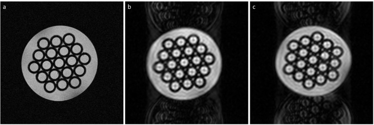
Figure 6 shows 2D cross sections of the water phantom acquired with the 2D spin-echo Fourier imaging sequence (a), the EPI sequence with the unshielded Gx readout gradient (b), and that with the unshielded Gy readout gradient (c). Because the pixel bandwidth was 15.625 Hz (∼0.04 ppm for the 400 MHz resonance frequency) in Fig. 6(a) and the magnetic field inhomogeneity caused a positional shift along the readout direction (horizontal direction) at each point, this MR image suggested that the magnetic field homogeneity in this plane was of the order of 0.1 ppm. This is because the positional shift of the 2D spin-echo image seemed less than three or four pixel lengths along the readout direction. The EPI images also demonstrated that the homogeneity of the magnetic field was of the order of 0.1 ppm in this plane because the magnetic field inhomogeneity caused a positional shift along the phase encoding direction (vertical direction) at each point. This is because the positional shift of the EPI image seemed less than three or four pixel lengths along the phase encoding direction.
Fig. 6.
Two-dimensional cross section of a water phantom acquired with (a) a spin-echo Fourier imaging sequence, (b) an echo-planar imaging (EPI) sequence with the Gx readout gradient, and (c) an EPI sequence with the Gy readout gradient.
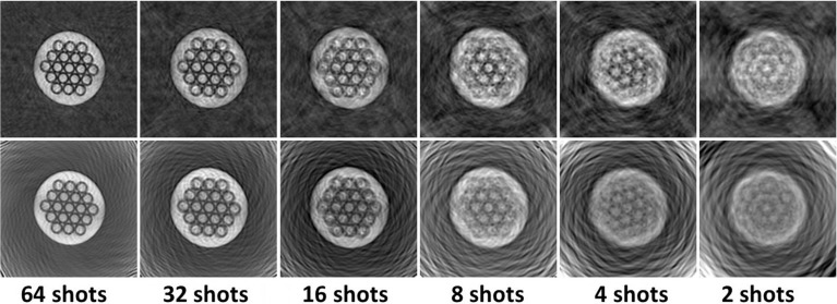
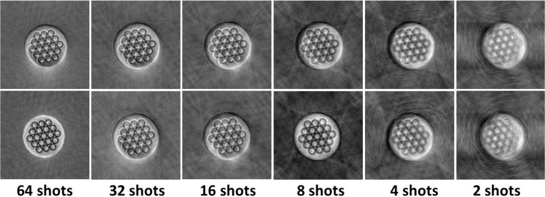
Spiral-scan images acquired with the self-shielded gradient coil reconstructed using both the nearest neighbor gridding method and the convolution gridding method for 64-, 32-, 16-, 8-, 4-, and 2-shot scans are presented in Fig. 7. Although neither image distortion nor phase distortion was observed for these spiral images, reconstruction noise (artifact) specific to the gridding methods was observed over the reconstructed images. In addition, serious image blurring caused by the magnetic field inhomogeneity in the slicing plane was observed for fewer-shot (2–16-shot) images.
Fig. 7.
Spiral images acquired with the self-shielded gradient coil reconstructed using the nearest neighbor gridding method (upper) and the convolution gridding method (lower). The numbers of the shots are displayed under the images. Real part images are shown.
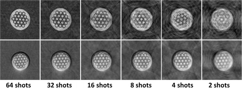
Spiral-scan images acquired with the self-shielded gradient coil and the unshielded gradient coil for 64-, 32-, 16-, 8-, 4-, and 2-shot scans and reconstructed with the nearest neighbor gridding method are shown in Fig. 8. The spiral images acquired with the unshielded gradient coil have severe intensity shading compared with those acquired with the self-shielded gradient coil, which was considered to be caused by the B0 eddy fields of the gradient coil.
Fig. 8.
Multishot spiral images acquired with the self-shielded gradient coil (upper) and the unshielded gradient coil (lower) reconstructed using the nearest neighbor gridding method. Real part images are shown.
Phase correction using the reference scan
Figure 9 presents the phase shift calculated from the echo peak signal of the reference scan and the shape of the gradient coil current for the Gx gradient field (a) and the Gy gradient field (b) for the unshielded gradient coil. The agreement between the detected phase shift (red circles) and the shape of the gradient coil current (blue line) is very good for Gy. However, the agreement is not so good for Gx.
Fig. 9.
Signal peak phase observed in the reference scan plotted together with the gradient waveform for the 8-shot spiral scan. The signal phase is plotted as circles, and the gradient waveform is drawn by the curves. (a) The reference scan with Gx ON and Gy OFF. (b) The reference scan with Gx OFF and Gy ON. The phase shift caused by the Gy gradient coil is much larger than that caused by the Gx gradient coil.
The uncorrected and corrected spiral images acquired with the unshielded gradient coil are shown in Fig. 10. The phase correction was performed only for the Gy gradient coil current because the phase shift caused by the Gx gradient coil current was relatively small (∼1/30 of that of Gy). Although the phase correction was not perfect, the severe intensity shading of the images acquired with 64- and 8-shots was well corrected and that acquired with other shots was slightly corrected.
Fig. 10.
Multishot spiral images acquired with the unshielded gradient coil. With (lower row) and without (upper low) phase correction. These images were reconstructed using the nearest neighbor gridding method. The upper figures are identical to the lower figures in Fig.8. Real part images are shown.
Effects of linear eddy fields
The spiral images acquired with both gradient coils for 64-shot sequences and 8-shot sequence for the unshielded gradient coil are shown in Fig. 11. It is clear from these images that the image size was reduced because of eddy current effects: about 89% (horizontally) and 92% (vertically) of the designed size with the self-shielded gradient coil, about 81% (horizontally) and 83% (vertically) of the designed size for the 64-shot sequence with the unshielded coil, and 88% (horizontally) and 91% (vertically) of the designed size for the 8-shot sequence with the unshielded gradient coil.
Fig. 11.
Multishot spiral images acquired with both gradient coils for 64-shot sequences (a): self-shielded, (b): unshielded) and 8-shot sequence for the unshielded gradient coil (c). The image acquired with the unshielded gradient coil was corrected by the phase shift measured using the reference scan. The image size of (a) is about 89% and 92%, and that of (b) is about 81% and 83%, and that of (c) is about 88% and 91% of the designed image size, for the horizontal and the vertical direction of the images, respectively. The image size reduction was caused by the linear eddy fields induced by the time variation of the readout gradients, Gx and Gy.
Discussion
Eddy current fields caused by the gradient coil current switching
The linear eddy fields could be decomposed into three components, and of these, the two major ones were tabulated (Tables 1 and 2). Because the shielded gradient was designed to cancel the gradient magnetic field on the surface of the room temperature magnet bore (diameter = 54 mm), the linear eddy field components with about 0.3 ms time constants, which were reduced by about 10–30 times, were considered to be induced on the room temperature magnet bore. This result clearly demonstrated that the shielding efficiency was higher than 90%. Because the thickness of the room temperature copper tube was 1.63 mm, most of the eddy currents induced outside of the gradient coils were considered to be produced by the room temperature bore tube.
However, very large linear eddy fields with short time constants (∼ 50 μs) were observed for the self-shielded gradient coil. We think that these eddy current fields were induced in the RF shield (a few tens of micrometers thick Cu sheet) wound inside of the self-shielded gradient coil and that (100 micrometer thick Cu sheet) wound outside of the RF probe, because the conductors with lower conductivity produce shorter decaying time constants of the eddy currents. However, because the time constant of this linear eddy field component was very short, the effect of this eddy field component on the slew rate of the gradient field was small.
The amplitudes of the B0 eddy fields caused by Gx and Gy for the unshielded gradient coil were 10–100 times larger than those for the self-shielded coil (Tables 3 and 4). We think that this result is essential for the severe shading artifact observed in spiral images acquired with the unshielded gradient coil.
Phase correction using the reference scan
In general, eddy fields generated by the applied field gradient, proportional to the gradient coil current, can be calculated using convolution integral of the step response of the eddy fields and the time derivative of the gradient coil current. However, if the time constant of the eddy field component is very short (e.g. tens of microsecond for B0 eddy field by Gy of the unshielded gradient, much shorter than the rotational cycle of the spiral trajectory [∼2 ms]), the step response of the eddy fields can be approximated as the delta function and the convolution integral can be approximated to be time derivative of the gradient coil current. Therefore, in this case, the B0 eddy field ΔB0(t) can be written as,
where α is a proportionality constant.
The angular frequency shift of the NMR signal caused by the B0 eddy field is, and thus the phase shift ΔΦ(t) caused by the B0 eddy field is
because I(0) = 0 for the spiral imaging sequences used in this study. This equation shows that the phase shift caused by the B0 eddy field is proportional to the waveform of the gradient coil current.
As described in “Results” section, Fig. 9 shows the phase shift calculated from the echo peak signal of the reference scan and the shape of the gradient coil current I(t) for the Gx gradient field (a) and the Gy gradient field (b) for the unshielded gradient coil. The agreement between the detected phase shift and the shape of the gradient coil current is very good for Gy, which justifies the above equation for the unshielded gradient coil. However, the agreement is not so good for Gx. This is because the time constant 0.84 ms of the primary component of the B0 eddy field caused by Gx is about 10 times larger than the time constant 0.084 ms of that caused by Gy. Therefore, the assumption that the time constant of the B0 eddy field component is much smaller than the rotational cycle of the spiral trajectory (∼2 ms) is not valid for Gx but valid for Gy. This is the reason for the difference of the agreement between Fig. 9a and b. Therefore, the phase of the NMR signal acquired with the spiral sequence can be corrected using the gradient coil current calibrated by the phase shift measured using the reference scan.
As shown in Fig. 10, the severe intensity shading of the images acquired with 64- and 8-shots was well corrected and that acquired with other shots was only slightly corrected. Although the reason why the intensity shading of the 8-shot image was well corrected was unclear, this result demonstrated the correctness of our approach.
Linear eddy field effects on the spiral scan images
The effect of the linear eddy fields on the spiral images is the reduction in image size (Fig. 11), because these eddy fields reduce the intensity of the gradient fields. Although the exact calculation of the field gradient amplitude using the linear eddy fields needs convolution integral of the time derivative of the gradient waveform and the step response of the linear eddy fields, the image size reduction can be understood qualitatively using the intensity of the linear eddy fields tabulated Tables 1 and 2.
Conclusion
We developed spiral-imaging sequences for a 9.4T standard vertical bore (54 mm) superconducting magnet using unshielded and self-shielded gradient coils. Although spiral images acquired with the self-shielded gradient coil using 64-shot scans showed no noticeable artifact, those acquired with the unshielded gradient coil showed a severe intensity-shading artifact, which was successfully corrected with the phase correction technique that we developed in this study using reference scans. We therefore conclude that spiral imaging sequences can be installed even with an unshielded gradient coil if we perform phase corrections using the reference scan.
Acknowledgments
We acknowledge Drs. Tomoyuki Haishi and Seitaro Hashimoto for the development of the 9.4T superconducting MRI system. We also thank Mr. Ryoichi Kose for providing the image reconstruction program using the convolution gridding and Mr. Yuta Kobayashi for analyzing the eddy current measurements. This work was supported by the System Development Program for Advanced Measurement and Analysis Project of the Japan Science and Technology Agency.
Footnotes
Conflicts of Interest
The authors declare that they have no conflicts of interest.
References
- 1.Ahn CB, Kim JH, Cho ZH. High-speed spiral-scan echo planar NMR imaging-I. IEEE Trans Med Imaging 1986; 5:2–7. [DOI] [PubMed] [Google Scholar]
- 2.Bernstein MA, King KF, Zhou XJ, Handbook of MRI pulse sequences, Burlington MA, Elsevier Academic Press, 2004; 928–954. [Google Scholar]
- 3.Glover GH. Simple analytic spiral k-space algorithm. Magn Reson Med 1999; 42:412–415. [DOI] [PubMed] [Google Scholar]
- 4.Tan H, Meyer CH. Estimation of k-space trajectories in spiral MRI. Magn Reson Med 2009; 61:1396–1404. [DOI] [PMC free article] [PubMed] [Google Scholar]
- 5.Qian Y, Zhao T, Hue YK, Ibrahim TS, Boada FE. High-resolution spiral imaging on a whole-body 7T scanner with minimized image blurring. Magn Reson Med 2010; 63:543–552. [DOI] [PMC free article] [PubMed] [Google Scholar]
- 6.Addy NO, Wu HH, Nishimura DG. Simple Method for MR gradient system characterization and k-Space trajectory estimation. Magn Reson Med 2012;68:120–129. [DOI] [PMC free article] [PubMed] [Google Scholar]
- 7.Bhavsar PS, Zwart NR, Pipe JG. Fast, variable system delay correction for spiral MRI. Magn Reson Med 2014; 71:773–782. [DOI] [PubMed] [Google Scholar]
- 8.Kodama N, Kose K. Echo-planar imaging for a 9.4Tesla vertical-bore superconducting magnet using an unshielded gradient coil. Magn Reson Med Sci 2016; 15:395–404. [DOI] [PMC free article] [PubMed] [Google Scholar]
- 9.Hashimoto S, Kose K, Haishi T. Development of a pulse programmer for magnetic resonance imaging using a personal computer and a high-speed digital input-output board. Rev Sci Instrum 2012; 83:053702. [DOI] [PubMed] [Google Scholar]
- 10.Bernstein MA, King KF, Zhou XJ, Handbook of MRI pulse sequences, Burlington MA, Elsevier Academic Press, 2004; 316–331. [Google Scholar]
- 11.Jackson JI, Meyer CH, Nishimura DG, Macovski A. Selection of a convolution function for Fourier inversion using gridding [computerized tomography application]. IEEE Trans Med Imaging 1991; 10:473–478. [DOI] [PubMed] [Google Scholar]


