Abstract
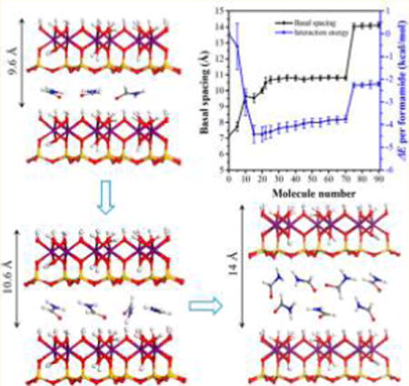
Molecular dynamics simulations were performed on kaolinite–formamide complex models with various numbers of formamide molecules loaded in the kaolinite interlayer to explore the basal spacing, energetics, and structure evolution of the kaolinite–formamide complex during the intercalation process. Additionally, the interfacial interactions of formamide with kaolinite interlayer surfaces were calculated. The calculation revealed that the basal spacing of kaolinite was enlarged to 9.6 Å at the beginning of intercalation. Formamide was arranged as a monolayer structure in the kaolinite interlayer with the molecular plane oriented at small angles with respect to the interlayer surface. With continuous intercalation, the basal spacing readily reached a stable stage at 10.6 Å, where formamide rearranged its structure by rotating the molecule plane along the C–N bond that was parallel to the interlayer surface, which resulted in the molecular plane orienting at higher angles with respect to the interlayer surface. During this process, the C═O groups oriented toward the hydroxyl groups on the interlayer octahedral surface, and one of N–H bonds progressively pointed toward the basal oxygens on the opposing interlayer tetrahedral surface. Continuous intercalation can enlarge the basal spacing to more than 14 Å with the prerequisite of overcoming the energy barrier, and then formamide evolved to a disordered bilayer structure in the kaolinite interlayer. The affinity of kaolinite interlayer surfaces for formamide motivated the intercalation process. The octahedral surface displayed a relatively larger affinity toward formamide compared to the tetrahedral surface partially due to the presence of hydroxyl groups that are more active in the intermolecular interactions with formamide.
Graphical abstract
INTRODUCTION
Kaolinite is a layered aluminosilicate with perfect 1:1 layer structure consisting of one silica tetrahedral layer and one alumina octahedral layer, which are connected by the shared plane of oxygens. The basic structural unit has two different surfaces parallel to the (001) plane due to the 1:1 layer structure. One is a tetrahedral surface covered by the basal oxygens of the tetrahedral sheet, and the other one is an octahedral surface formed by the surface hydroxyl groups of the octahedral sheet. The basic structural unit is linked by hydrogen bonds formed between the hydroxyl groups on the octahedral surface and the opposing basal oxygen atoms on the tetrahedral surface.1 Kaolinite intercalation is involved in breaking the inherent H-bonds in the kaolinite interlayer by the insertion of inorganic or organic guest species into the interlamellar region. Kaolinite intercalation was initially used to distinguish the kaolinite from other clay minerals.2 It is also widely used in various chemical, environmental, and material-related industrial applications.3–7 The intercalation can weaken the cohesive energy between kaolinite layers and facilitate the peeling of kaolinite stacks to platelets with an improved specific surface area, aspect ratio, and optical properties for meeting the requirement of industrial applications.4,8 Kaolinite intercalated with organic species is of great importance because of the enlarged interlayer space and modified interlayer surfaces, which can promote the adsorptive properties for removing contaminants9 and interfacial compatibility with the polymer matrix when used as a reinforcing filler for preparing kaolinite-based hybrid materials.3 However, the H-bonds in the kaolinite interlayer inhibit the intercalation process and limit the intercalation species to a small group of polar molecules such as urea, dimethyl sulfoxide (DMSO), potassium acetate, formamide, and N-methylformamide (NMF), which can directly intercalate in kaolinite due to their excellent capability of forming H-bonds with kaolinite interlayer surfaces.10,11 Although a limited number of compounds have the ability to directly intercalate into kaolinite, the number of compounds can be extended by the method of displacement intercalation, which involves replacing directly intercalated species such as ammonium acetate or NMF with compounds such as monomers that cannot directly intercalate into kaolinite.12,13 This method opens up a new research area for the application of kaolinite in hybrid materials.
The interfacial structures and interactions of kaolinite intercalation complexes have attracted great interest and have been widely investigated using experimental and theoretical methods.10,11,14–16 Formamide is one of the commonly used intercalation agents for preparing kaolinite or the dickite intercalation complex. Its arrangement in kaolinite and the dickite interlayer and its interactions with interlayer surfaces were studied using infrared spectroscopy (IR), X-ray diffraction (XRD), and nuclear magnetic resonance (NMR).11,17–20 The XRD was used to determine the conformation of formamide in a clay mineral interlayer, and the IR and NMR studies were applied to complement the structural data on the bonding of intercalated formamide to the interlayer surfaces. On the basis of the experimental analyses, formamide is known to form hydrogen bonds between the carbonyl group and the NH group with hydroxyl groups on the octahedral surface and basal oxygens on the tetrahedral surface, respectively. Two types of main conformations of formamide in the clay mineral interlayer were proposed. One is that the formamide molecule functions as a pillar arranging almost vertically between clay mineral layers, and the other is that the formamide molecule pillar is laid down with the C–N bond vector parallel to the clay mineral surface but the molecular plane is perpendicular to the clay mineral layers. The experimental method, however, remains inconclusive regarding the precise arrangement of the guest species at the atomic scale in the clay mineral interlayer. In addition, the detailed interaction of guest species with two types of interlayer surfaces is hard to reach by traditional experimental methods. Molecular simulations have been developed as a powerful tool for exploring the interfacial structure and interactions of clay mineral surfaces with organics and solutions.21–26 A theoretical method of quantum chemistry has been used to study the interactions of formamide with kaolinite and dickite surfaces.27–31 It is generally considered that the octahedral surface hydroxyl groups form relatively strong H-bonds with formamide, and the basal oxygens of the tetrahedral surface are able to form relatively weak H-bonds with formamide. The Monte Carlo (MC) simulation of the stable basal spacing and structure of the kaolinite–formamide complex showed that the molecular plane of formamide was basically parallel to the kaolinite surface.14
Although the interfacial structure and interactions of the kaolinite–formamide complex have been experimentally and theoretically determined, the basal spacing, energetics, and structure evolution of the kaolinite–formamide complex during the intercalation process were rarely systematically studied, and the interfacial structure and interaction of the complex are still debatable. In the present study, the molecular dynamics (MD) simulations were carried out on a series of kaolinite–formamide complex models with various numbers of formamide molecules loaded into the kaolinite interlayer to explore such interest. It can enhance the understanding of the intercalation process of small molecules in kaolinite, which is challenging to obtain by conventional experimental techniques.
Models and Simulations
The initial kaolinite model was built from the unit cell with the structural formula of Al4Si4O10(OH)8, where the atomic positions of the model were adopted from the crystal structure of kaolinite determined with a neutron power diffraction experiment.32 The unit cell was expanded to an 8 × 5 × 1 supercell with x and y dimensions of 41.2 and 44.67 Å, respectively. In order to investigate the arrangement of formamide in the kaolinite interlayer and its interaction with interlayer surfaces, the kaolinite supercell was cleaved along the (001) plane to create the alumina surface terminated with a plane of surface hydroxyl groups. The formamide amporphous slab having the same x and y dimensions of the kaolinite supercell was stacked on the alumina surface to create the alumina surface–formamide model. Then two alumina surface–formamide models were stacked along the z axis, creating the kaolinite–formamide complex possessing two interlayer spaces as shown in Figure 1. In order to investigate the basal spacing, energetics, and structure evolution of kaolinite–formamide complexes during the intercalation process, the two interlayers were expanded synchronously by continuously loading 5 to 90 formamide molecules into the formamide amorphous slab. The initial z dimension of kaolinite–formamide complexes ranged from 29.07 to 49.37 Å depending on the loading number of formamide molecules.
Figure 1.
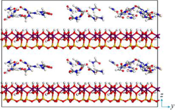
Initial kaolinite–formamide complex model in the case of 35 loaded formamide molecules in each interlayer. Atoms are colored as follows: Si (orange), Al (purple), O (red), H (white), N (blue), and C (gray).
The Clay force field,33 ClayFF,34 and Interface force field35 were widely used for modeling clay minerals, which have been successfully applied to the clay mineral systems of environmental interest and clay-mineral-based hybrid materials.26,36,37 In the present study, the CVFF-interface force field was adopted to describe the systems of the kaolinite–formamide complex. The CVFF-interface force field is the extension of CVFF, which incorporated the force field parameters developed for clay minerals in the CVFF to enable the simulations of clay minerals–organics interfaces.35,38 This force field has been successfully used to describe the kaolinite–organics interfaces.39,40 The potential function of the force field and the force field parameters for kaolinite and formamide models are provided in the Supporting Information.
The MD simulations were performed with the periodic boundary condition applied for all three dimensions using the LAMMPS package.41 The ensemble implemented was the NPT with a constant temperature of 300 K and a constant pressure of 0.1 MPa. The temperature was controlled by the Nose–Hoover thermostat, and the pressure was controlled using the Nose–Hoover barostat.41 Energy minimization was performed on all systems for 10 000 steps using the conjugate gradient technique prior to running MD simulations. Five nanosecond NPT simulation runs were first performed to ensure the equilibrium of the systems, followed by 1 ns production runs. The trajectories of the models were recorded for analyses at 2000 fs intervals during the production runs. The motion equations were integrated by using the Verlet algorithm42,43 with a time step of 1 fs. The long-range electrostatic energy was computed with the Ewald method,44 using a real-space cutoff of 10 Å. The short-range van der Waals energy was truncated at 10 Å with an analytical tail correction. During the MD simulations, the formamide molecules were modeled as a flexible structure.
Interfacial Structure
Density Distribution
The arrangement of formamide in the kaolinite interlayer was obtained by calculating the one-dimensional atomic density normal to the interlayer surface defined as
| (1) |
where i represents the atoms of the formamide molecule; Ni refers to the number of i atoms distributed in the bin of thickness δ located a distance z from the interlayer surface; and A is the area of the interlayer surface.
Orientation Distribution
The distribution of orientation angles of formamide molecules in the kaolinite interlayer was also calculated to track their structure. The orientation angles were defined as the angles of vector of C═O, C–N, and N–H bonds and the normal vector of the molecular plane of formamide with respect to the z axis (the direction perpendicular to the kaolinite interlayer surface) as shown in Figure 2. This method has been used to understand the arrangement of small organic molecules in the kaolinite interlayer.14,15
Figure 2.
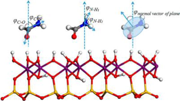
Definition of orientation angles: φC═O, φC–N, φN–H, and φnormal vector of plane. Atoms are colored as in Figure 1.
Interfacial Interaction
Radial Distribution Function (RDF)
RDF is one of the commonly used correlation functions for speculating about the interactions between atoms by estimating the density of atom B surrounding atom A at a given distance. The peaks in the RDF file represent the large occurrence frequency of atom B surrounding atom A. The RDF was calculated as
| (2) |
where ρB is the number density of atom B and dnAB is the average number of B atoms within the distance range of r to r + dr from atom A. The running coordination numbers (RCN) of atom B surrounding atom A can be calculated by integrating the RDF peaks.
Hydrogen Bonding
The geometric criteria were used to define the hydrogen bonds between formamide molecules and kaolinite interlayer surfaces. The proton acceptor and proton donor were considered to form H-bonds if they satisfied the following criteria: the distance between H⋯Y is <3.2 Å and the angle of X–H⋯Y is >90°,45,46 where the X and Y represent the proton donor and proton acceptor, respectively.
Interaction Energy
In order to study the thermodynamics of the intercalation process, the interaction energies (ΔE) of both kaolinite interlayer surfaces with intercalated formamide were calculated using the following equation.47,48 The analogous method has been used to compute the hydration and swelling energetics of layered double hydroxides49,50 and kaolinite intercalation by dimethyl sulfoxide.15
| (3) |
Esurfaces+formamide is the potential energy of the complex of interlayer surfaces (octahedral surface and tetrahedral surface) – formamide; Esurfaces and Eformamide are the energies of isolated interlayer surfaces and isolated formamide molecules, respectively. In the present study, the lower kaolinite layer with the octahedral surface facing the lower formamide slab of the model represents the octahedral surface; the upper kaolinite layer with the tetrahedral surface facing the lower formamide slab represents the tetrahedral surface (Figure 1). The lower formamide slab sandwiched between two kaolinite layers was chosen as the target for the calculation of interaction energies and the aforementioned calculation of interfacial structure, RDF, and hydrogen bonds. A vacuum slab with a thickness of 40 Å was added above the model perpendicular to the interlayer surface prior to the calculation of single-point energy. The single-point energies of Esurfaces+formamide, Esurfaces, and Eformamide of each frame recorded in the production runs were first computed. Then the interaction energies were computed using eq 3 and averaged over all the recorded frames.
In order to compare the binding affinity of each interlayer surface toward formamide, the interaction energies of formamide with the interlayer octahedral surface and tetrahedral surface were also calculated, respectively, using the same method. When calculating the interaction energy between the octahedral surface and formamide, the upper kaolinite layer and upper formamide slab (Figure 1) were removed to avoid their effect on the calculation of single-point energies of target systems. Accordingly, the lower kaolinite layer and the upper formamide slab were removed when calculating the interaction energy between the tetrahedral surface and formamide. In fact, the interaction energies calculated on the basis of the force field represent the intermolecular interaction that is composed of electrostatic energy and van der Waals energy. The electrostatic and van der Waals interaction energies were also calculated separately to clarify their proportions accounting for the interaction energies. This method was adopted to the study of the binding affinity of kaolinite interlayer surfaces toward alkane surfactants with neutral and ionic headgroups, where the schematic of how to compute the interaction energies of the target species with each interlayer surface was provided.47
RESULTS AND DISCUSSION
Basal Spacing and Energetics Evolution
XRD analyses of the kaolinite–formamide complex have shown the substantial preference for the formation of the monolayer structure of formamide in the kaolinite interlayer. The intercalation mechanism of formamide in kaolinite and the evolution of basal spacing and the interfacial structure of the kaolinite–formamide complex during the intercalation process are interesting to investigate. In the present study, MD simulations of kaolinite–formamide complex models with various numbers of formamide molecules loaded in the kaolinite interlayer were performed to explore such interest. The calculated basal spacing as shown in Figure 3 indicates the formation of three possible stable structures marked with three plateaus of basal spacing at around 9.6, 10.6, and 14 Å. At the beginning of the intercalation process, a small number of formamide molecules can expand the basal spacing of kaolinite to 9.6 Å, and then the basal spacing was enlarged and stabilized at around 10.6 Å with the continuous intercalation of formamide. Basal spacings of 9.6 and 10.6 Å correspond to the monolayer structure of formamide in the kaolinite interlayer. In order to study the themodynamics of the intercalation process, the interaction energy (ΔE) was calculated. The ΔE (Figure 3) calculated on the basis of the complex models that produced the basal spacing in the range of 9.6 to 10.6 Å is more negative, indicating the strong preference for the formation of the monolayer structure of formamide in the kaolinite interlayer. The energy jump is less defined when the basal spacing is increased to 10.6 from 9.6 Å, which means there is almost no need to overcome the energy barrier to expand the kaolinite basal spacing from 9.6 to 10.6 Å through the intercalation of formamide. Therefore, the kaolinite–formamide complex with a basal spacing of 10.6 Å is a relatively stable structure, agreeing well with the study of Monte Carlo simulation.14 The basal spacings produced by both MD and Monte Carlo simulations, however, are slightly larger than the experimentally obtained one (10.1–10.2 Å) with a deviation of 4–5%.11,17,18 This may be caused by the limitation use of the potential model. The molecular ratio of formamide per host unit A14Si4O10(OH)8 of kaolinite–formamide complex models is less than 0.9 with the formamide arranged monolayer structure in the interlayer space, which is close to that (1.0) deduced by thermogravimetric and NMR studies.17 Figure 3 shows that the basal spacing is sharply expanded to 14 Å when the loading number of formamide molecules is more than 70. However, ΔE also displays a sharp increase of 1.5 kcal/mol, indicating that the continuous enlargement of kaolinite basal spacing needs to overcome the energy barrier. Thus, the kaolinite–formamide complex with a basal spacing of 14 Å was rarely reported.11,14,17,18 The thermodynamic calculation of the kaolinite intercalation process indicates that the kaolinite interlayer can be considerably enlarged by small molecules under the particular condition of conquering the energy barrier to form a bilayer structure in the interlayer space. It should be noted that the ΔE calculated in the present study is the internal energy rather than the Gibbs free energy because the entropic energy was not taken into account. Thus, the results cannot be directly applied to predict the chemical equilibria.25
Figure 3.
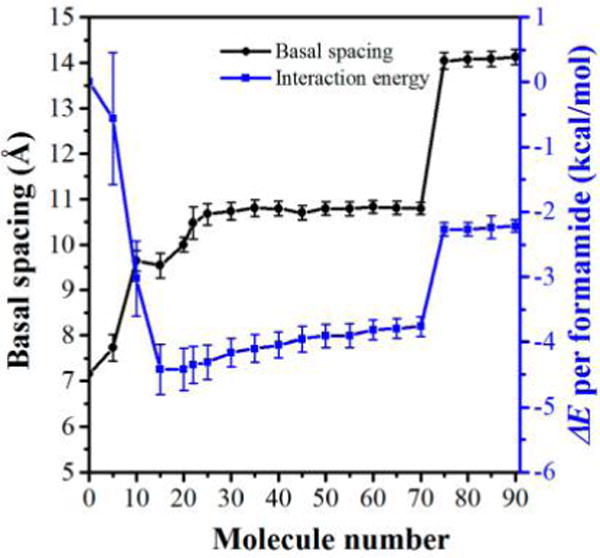
Basal spacing (left scale of the y axis) and ΔE (right scale of the y axis) evolution with an increasing number of formamide molecules in the interlayer of kaolinite–formamide complexes calculated by MD simulations.
Structure Evolution
The structural evolution of formamide molecules in the kaolinite interlayer during the intercalation process was obtained by analyzing the one-dimensional atomic density and orientation of formamide molecules. Here, the kaolinite–formamide complex models that produced basal spacings of 9.6, 10.6, and 14 Å, respectively, were chosen for the calculation of the atomic density and orientation of formamide molecules in the interlayer space. The density profiles of oxygen atoms, carbon atoms, and nitrogen atoms of formamide in Figure 4a,b display a single peak, verifying the monolayer structure of formamide in the kaolinite interlayer with basal spacings of 9.6 and 10.6 Å. These atomic density profiles have two peaks residing on either side of the middle plane of the interlayer space as shown in Figure 4c, indicating that formamide evolved to the bilayer structure once the basal spacing was increased to 14 Å. The oxygen atoms, carbon atoms, and nitrogen atoms of formamide molecules in the kaolinite interlayer with a basal spacing of 9.6 Å are almost at the same level in the middle plane of the interlayer space, indicating that the molecular planes of formamide molecules orient at small angles with respect to the interlayer surface. The corresponding distribution frequency of orientation angle φnormal vector of plane (Figure 5a) also reflects this behavior, where a peak centered at 18° is observed. Because the orientation angle φnormal vector of plane is defined as the angle of the normal vector of the formamide molecular plane with respect to the z axis (Figure 2), it is equal to the angle between the molecular plane of formamide and the interlayer surface. Figure 4a shows that the oxygen atoms of formamide are located closer to the hydroxyl groups on the octahedral surface, suggesting that the C═O groups of formamide tend to interact with the hydroxyl groups through H-bonds. This is also reflected by the distribution frequency of orientation angle φC═O that has a single broad peak located at 100°, which means that the C═O groups preferably point to the hydroxyl groups on the octahedral surface. The C–N bonds of formamide molecules orient nearly parallel with the interlayer surface since orientation angle φC–N has a single peak located at around 93°. The hydrogen atoms in NH groups and HC═O groups distribute diffusely in the whole kaolinite interlayer (Figure 4a) and interact with both interlayer surfaces. The distribution frequencies of φN–H1 and φN–H2 also exhibit scattering characteristics (Figure 5a), which suggests the dynamic arrangement of formamide molecules in the interlayer space. The relatively stable structure of formamide in the kaolinite interlayer is the molecular plane of formamide that orients at an angle of 18° with respect to the interlayer surface with C═O groups pointing to the hydroxyl groups on the octahedral surface as shown in the snapshot in Figure 5a.
Figure 4.
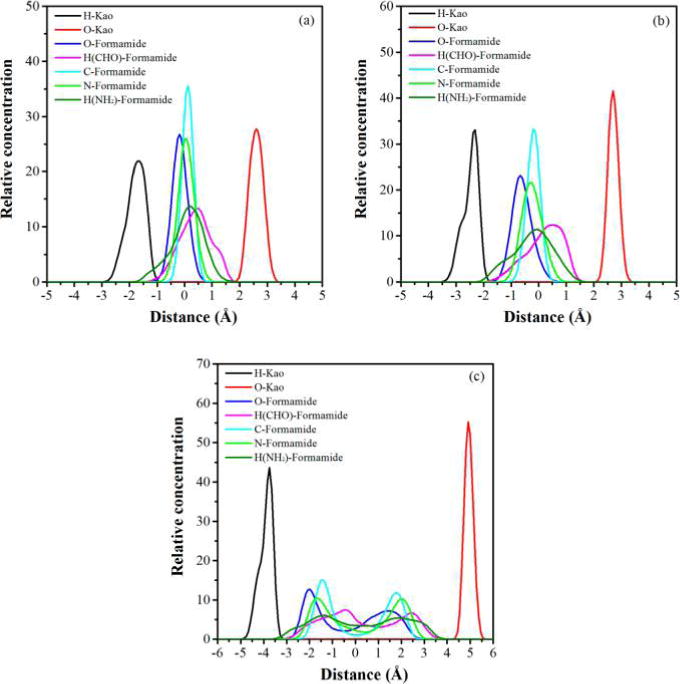
Atomic density of formamide molecules in the kaolinite interlayer normal to the interlayer surface obtained from MD simulations for kaolinite–formamide complexes with basal spacings of (a) 9.6, (b) 10.6, and (c) 14 Å. H-Kao and O-Kao represent the hydrogen atoms of hydroxyl groups on the octahedral surface of the lower kaolinite layer and the basal oxygen atoms on the tetrahedral surface of the upper kaolinite layer in the kaolinite–formamide complex model (Figure 1). The origin of the coordinate is located in the middle plane of the interlayer space.
Figure 5.
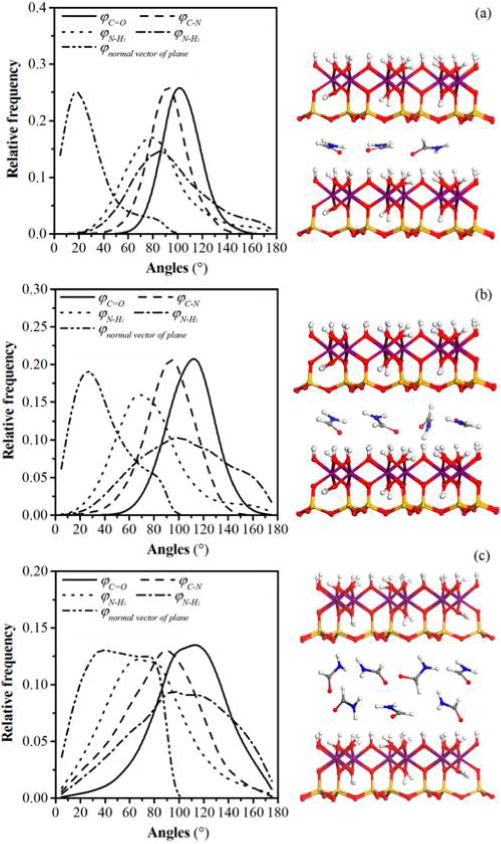
Distribution frequencies of orientation angles φC═O, φC–N, φN–H, and φnormal vector of plane of formamide molecules in the interlayer of kaolinite–formamide complexes with basal spacings of (a) 9.6, (b) 10.6, and (c) 14 Å and the corresponding snapshots. Atoms are colored as in Figure 1.
With the basal spacing expanded to 10.6 Å, the distances between the atomic levels of formamide molecules, for example, the distance between the oxygen atom peak and the carbon atom peak is also enlarged as shown in Figure 4b. Additionally, the peak of orientation angle φnormal vector of plane (Figure 5b) is shifted to a higher value of 26°. This means that the molecular planes of formamide molecules orient at higher angles with respect to the interlayer surface with the increase in basal spacing. The Monte Carlo simulation of the kaolinite–formamide complex with almost the same basal spacing reported the parallel arrangement of the molecular plane of formamide with respect to the kaolinite surface.14 The peak of φC═O is also shifted to a higher value of 113°, the peak of φN–H1 shifted to lower value of 70°, and the peak of φC–N is almost unchanged (Figure 5b). This suggests that the formamide molecules rearrange their structure by rotating the molecular plane along the C–N bond that is parallel to the interlayer surface with the increase in basal spacing. During this process, the C═O groups still orient toward the hydroxyl groups on the octahedral surface, and one of the N–H bonds progressively points to the basal oxygens on the opposing interlayer tetrahedral surface. Meanwhile, the hydrogen atoms in the HC═O groups are progressively shifted closer to the basal oxygens on the tetrahedral surface (Figure 4b). Analogous to the kaolinite–formamide complex with a basal spacing of 9.6 Å, the nonzero distribution frequency of φnormal vector of plane also indicates the dynamical arrangement of formamide molecules in the interlayer space. The relatively stable structure is that the molecular plane of formamide orients at angle of around 26° with respect to the interlayer surface with C═O groups still pointing to the hydroxyl groups on the octahedral surface and one of the N–H bonds orienting toward the basal oxygens on the tetrahedral surface (Figure 5b). A similar position and orientation of formamide in the kaolinite interlayer was revealed in the quantum chemistry calculation at the PBE/6-31G level.31
When the basal spacing was increased to 14 Å, the formamide molecules evolved to a bilayer structure in the kaolinite interlayer (Figure 4c). The distribution frequencies of orientation angles are more scattered as shown in Figure 5c, especially for the φnormal vector of plane that does not show well-defined peaks. Additionally, φC═O, φC–N, and φN–H are all shifted to higher values, suggesting the evolution of a significantly disordered arrangement of formamide molecules due to the large interlayer space allowing them to rearrange their structure freely. Their representative conformations are displayed in the snapshot in Figure 5c. In spite of the disordered arrangement, the interactions between formamide molecules and interlayer surfaces remains unchanged. Figure 4c shows that the oxygen atoms of the lower formamide layer of the formamide bilayer still interact favorably with the hydroxyl groups on the octahedral surface, and the hydrogen atoms in NH and HC═O groups in the upper formamide layer interact favorably with the basal oxygens on the tetrahedral surface.
Interfacial Interactions
The interfacial interactions of the kaolinite–formamide complex can provide insight into the nature of the driving force motivating the intercalation process. The kaolinite–formamide complex has a relatively stable basal spacing of 10.6 Å. In addition, no well-defined energy jump was observed when the basal spacing was increased from 9.6 to 10.6 Å. Thus, the model of a kaolinite–formamide complex with a basal spacing of 10.6 Å was chosen for the calculation of interfacial interactions. The radial distribution function (RDF) and corresponding running coordination numbers (RCN) and hydrogen bonds were calculated to access the interactions between kaolinite interlayer surfaces and formamide. The RDF of oxygen atoms in HC═O groups of formamide and hydrogen atoms of hydroxyl groups on the octahedral surface displays a sharp peak centered at 2.0 Å (Figure 6), indicating their favorable hydrogen bonding interaction. The corresponding RCN calculated by integrating the sharp RDF peak is around 3, which means each oxygen atom of formamide is coordinated by around three hydrogen atoms. The H-bond statistics shows that each oxygen atom of formamide forms an average of 2.68 H-bonds with an average bond length of 2.5 Å with the hydrogen atoms of hydroxyl groups. Although each oxygen atom of formamide is coordinated by around three hydrogen atoms, not all of them simultaneously participate in the formation of H-bonds. This finding is also supported by the theoretical study of the interactions of formamide with kaolinite and dickite surfaces.27–29 The experimental studies of formamide intercalated in kaolinite and dickite also suggested that the carbonyl oxygen atom forms almost three H-bonds with the hydroxyl groups on the octahedral surface.17,19,20 The RDF peaks of hydrogen atoms in HC═O groups and NH groups of formamide with basal oxygens on the tetrahedral surface are less well-defined (Figure 6), suggesting the relatively weaker interactions between them. This is also reflected directly in the H-bonds statistics, which shows that each hydrogen in the HC═O group forms an average of less than 1.4 H-bonds with a bond length of 2.8 Å with basal oxygens on the tetrahedral surface, and each hydrogen in the NH group forms an average of 1.5 H-bonds with a bond length of 2.8 Å with basal oxygens on the tetrahedral surface. This H-bonds scheme agrees well with the quantum chemistry studies on the intermolecular interactions of formamide with the kaolinite tetrahedral surface.30,31 Other theoretical and experimental studies,17–20,27–29 however, did not mention the formation of H-bonds involved in the hydrogen atom in the HC═O group. Moreover, the H-bond statistics shows that a certain number of NH groups of formamide are also hydrogen bonded weakly with the oxygen atoms of hydroxyl groups on the octahedral surface. The average number of H-bonds is 1.5 per hydrogen in the NH group with an average bond length of 2.7 Å. Some hydroxyl groups on the octahedral surface are oriented parallel with the interlayer surface, leading to the exposure of the oxygen atoms to the interlayer space.46 Additionally, some of the NH groups of formamide point to the octahedral surface (Figure 5b), allowing them to form H-bonds with the oxygen atoms of hydroxyl groups. This observation agrees well with the theoretical study of formamide intercalated in dickite27,28 but is not in agreement with the conclusion from NMR studies,17,20 where both NH groups were suggested to weakly hydrogen bond with basal oxygens on the tetrahedral surface. The H-bond scheme calculated in the present study agrees modestly with that calculated using quantum chemistry. The H-bond length calculated using the MD method is relatively larger since it produced a relatively larger basal spacing of the kaolinite–formamide complex and the dynamical arrangement of formamide in the kaolinite interlayer during the MD simulations.
Figure 6.
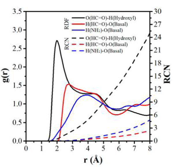
Radial distribution functions (RDF) and running coordination numbers (RCN) calculated for oxygen atoms in HC═O groups of formamide with hydrogen atoms of hydroxyl groups on the octahedral surface and hydrogen atoms in HC═O and NH groups of formamide with basal oxygens on the tetrahedral surface.
The lateral atomic density contours provide valuable insight into the distribution of the atomic density of formamide on the interlayer surface and the nature of interactions between the interlayer species with the interlayer surfaces. For oxygen atoms in HC═O groups of formamide on the octahedral surface, they reside principally in the center of a triangular area surrounded by three hydroxyl groups including the octahedral vacancy (Figure 7a), where each oxygen atom can ideally accept three hydrogen atoms of the hydroxyl groups. Thus, the oxygen atoms of formamide were found to be coordinated by an average of three hydrogen atoms based on the RDF and RCN calculation as mentioned above. This suggests that the hydroxyl triangular area on the octahedral surface is the predominant adsorption site for oxygen atoms of formamide, where the oxygen atoms can readily form H-bonds with the surrounding hydroxyl groups. The hydrogen atoms in HC═O and NH groups, which are hydrogen bonded with basal oxygens on the tetrahedral surface, mainly distribute at the ditrigonal cavity on the tetrahedral surface (Figure 7b,c). The ditrigonal cavity is surrounded by basal oxygen atoms, where the hydrogen atoms of formamide can readily form H-bonds with them. The distribution of hydrogen atoms of formamide on the tetrahedral surface is more diffuse compared to the distribution of oxygen atoms of formamide on the octahedral surface, which is not surprising considering the relatively weak hydrogen bonding interactions of hydrogen atoms of HC═O and NH groups with basal oxygens on the tetrahedral surface.
Figure 7.
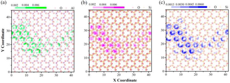
Lateral atomic density contour maps of (a) oxygen atoms in HC═O groups of formamide on the interlayer octahedral surface, (b) hydrogen atoms in HC═O groups, and (c) hydrogen atoms in NH groups of formamide on the interlayer tetrahedral surface. Green contours, the oxygen atom in HC═O groups; magenta contours, the hydrogen atom in HC═O groups; and blue contours, the hydrogen atom in NH groups.
The ΔE of formamide with two types of kaolinite interlayer surfaces were also calculated to further explore the interfacial interactions of the kaolinite–formamide complex. The ΔE calculated based on the force field is composed of van der Waals energy and electrostatic energy. The decomposition of ΔE to the two components was also calculated to clarify their contributions to the interaction energies as shown in Figure 8. The negative value of ΔE calculated using eq 1 represents a favorable interaction. In contrast, the positive value represents the repulsive interaction. Figure 8 clearly shows that both the interlayer octahedral surface and the tetrahedral surface show an affinity for formamide, indicating that the attractive interactions of interlayer surfaces with formamide are energetically favorable for the intercalation of formamide. The ΔE per formamide with the octahedral surface averages −2.75 kcal/mol, which is −1.31 kcal/mol more negative than that with the tetrahedral surface (−1.44 kcal/mol), indicating the relatively stronger affinity of formamide for the octahedral surface. The affinity difference of formamide with the two types of interlayer surfaces is in line with that calculated using density functional theory.29 For the interaction of formamide with the octahedral surface, the electrostatic energy plays an important role, which accounts for 73% (−2.00 kcal/mol) of the interaction energy, and the van der Waals energy component is 17% (−0.75 kcal/mol). By contrast, the van der Waals energy component is larger than the electrostatic energy component for the interaction of formamide with the tetrahedral surface (Figure 8). The percentages of van der Waals energy and electrostatic energy components are 69% (−0.99 kcal/mol) and 31% (−0.45 kcal/mol), respectively. This is expected since the tetrahedral surface features a hydrophobic property,51 thus the van der Waals energy prevails in the interaction of formamide with the tetrahedral surface.
Figure 8.
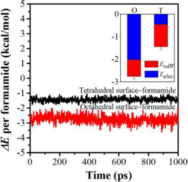
ΔE per formamide with kaolinite interlayer surfaces as a function of simulation time. The inset is the decomposition of ΔE to the van der Waals interaction energy (EvdW) and electrostatic interaction energy (Eelec) averaged over the production runs, where O and T represent the interactions of formamide with the interlayer octahedral surface and tetrahedral surface, respectively.
CONCLUSIONS
In this work, all-atom molecular dynamics simulations were performed to explore the basal spacing, energetics, and structure evolution of the kaolinite–formamide complex with various numbers of formamide molecules loaded in the kaolinite interlayer and the interfacial interactions of the kaolinite–formamide complex with a basal spacing of 10.6 Å. It was found that the basal spacing of the complex can be stabilized at around 9.6, 10.6, and 14 Å and even larger values with the continuous intercalation process. Formamide was arranged as a monolayer structure in the kaolinite interlayer at basal spacings of 9.6 and 10.6 Å and evolved to bilayer structure when the basal spacing was increased to 14 Å. The energy barrier almost did not need to be overcome to increase the basal spacing from 9.6 to 10.6 Å for the kaolinite–formamide complex. However, the energy barrier needed to be conquered to continue to enlarge the basal spacing to 14 Å. The molecular plane of formamide was oriented at small angles with respect to the kaolinite interlayer surface at the beginning of the intercalation process. With the increase in basal spacing, the formamide molecules rearranged their structure by rotating the molecular plane along the C–N bond that was parallel to the interlayer surface. During this process, the C=O groups oriented toward the hydroxyl groups on the octahedral surface, and one of the N–H bonds progressively pointed to the basal oxygens on the opposing tetrahedral surface. When the basal spacing was increased to 14 Å, the formamide molecules evolved to a disordered bilayer structure in the kaolinite interlayer. For the interfacial interaction of the kaolinite–formamide complex, the oxygen atoms of HC=O groups of formamide acting as proton acceptors were strongly hydrogen bonded with the hydroxyl groups on the octahedral surface. The hydrogen atoms of HC=O groups were weakly hydrogen bonded with basal oxygens on the tetrahedral surface. The NH groups of formamide functioned as a proton donor interacting with both basal oxygens on the tetrahedral surface and hydroxyl groups on the octahedral surface through relatively weak hydrogen bonds. Because of the intermolecular interactions of formamide with kaolinite interlayer surfaces, the oxygen atoms of HC=O groups principally distributed over the hydroxyl triangular area including the octahedral vacancy on the octahedral surface. The hydrogen atoms in HC=O and NH groups mainly resided at the ditrigonal cavity on the tetrahedral surface. The kaolinite interlayer octahedral and tetrahedral surfaces both showed attractive interactions with formamide, which was energetically favorable for driving formamide intercalcation in kaolinite.
Supplementary Material
Acknowledgments
Research reported in this publication was supported by the National Natural Science Foundation of China (51034006), the China Postdoctoral Science Foundation (2017M620956), and the National Institute of Environmental Health Sciences of the National Institutes of Health, United States (P42 ES004911). The contents are solely the responsibility of the authors and do not necessarily represent the official views of the National Institutes of Health, United States. Support from the China Scholarship Council (CSC) for S.Z.’s study at Michigan State University is also gratefully acknowledged. The computation resources and time provided by the High Performance Computing Center (HPCC) at Michigan State University are also acknowledged.
Footnotes
Supporting Information
The Supporting Information is available free of charge on the ACS Publications website at DOI: 10.1021/acs.jpcc.7b10234.
Description of the selected force field and the corresponding force field parameters for kaolinite and formamide models. (PDF)
ORCID
Qinfu Liu: 0000-0001-8992-7571
Notes
The authors declare no competing financial interest.
References
- 1.Young R, Hewat A. Verification of the Triclinic Crystal Structure of Kaolinite. Clays Clay Miner. 1988;36:225–232. [Google Scholar]
- 2.Wada K. Lattice Expansion of Kaolin Minerals by Treatment with Potassium Acetate. Am Mineral. 1961;46:78–91. [Google Scholar]
- 3.Dedzo GK, Detellier C. Functional Nanohybrid Materials Derived from Kaolinite. Appl Clay Sci. 2016;130:33–39. [Google Scholar]
- 4.Murray HH, Kogel JE. Engineered Clay Products for the Paper Industry. Appl Clay Sci. 2005;29:199–206. [Google Scholar]
- 5.Liu Q, Zhang Y, Xu H. Properties of Vulcanized Rubber Nanocomposites Filled with Nanokaolin and Precipitated Silica. Appl Clay Sci. 2008;42:232–237. [Google Scholar]
- 6.Cheng H, Zhou Y, Feng Y, Geng W, Liu Q, Guo W, Jiang L. Electrokinetic Energy Conversion in Self-Assembled 2D Nanofluidic Channels with Janus Nanobuilding Blocks. Adv Mater. 2017;29:1700177. doi: 10.1002/adma.201700177. [DOI] [PubMed] [Google Scholar]
- 7.Matusik J, Matykowska L. Behaviour of Kaolinite Intercalation Compounds with Selected Ammonium Salts in Aqueous Chromate and Arsenate Solutions. J Mol Struct. 2014;1071:52–59. [Google Scholar]
- 8.Tsunematsu K, Tateyama H. Delamination of Urea-Kaolinite Complex by Using Intercalation Procedures. J Am Ceram Soc. 1999;82:1589–1591. [Google Scholar]
- 9.Bhattacharyya KG, Gupta SS. Adsorption of a Few Heavy Metals on Natural and Modified Kaolinite and Montmorillonite: A Review. Adv Colloid Interface Sci. 2008;140:114–131. doi: 10.1016/j.cis.2007.12.008. [DOI] [PubMed] [Google Scholar]
- 10.Ledoux RL, White JL. Infrared Studies of Hydrogen Bonding Interaction between Kaolinite Surfaces and Intercalated Potassium Acetate, Hydrazine, Formamide, and Urea. J Colloid Interface Sci. 1966;21:127–152. [Google Scholar]
- 11.Olejnik S, Posner AM, Quirk JP. The Intercalation of Polar Organic Compounds into Kaolinite. Clay Miner. 1970;8:421–434. [Google Scholar]
- 12.Sugahara Y, Satokawa S, Kuroda K, Kato C. Evidence for the Formation of Interlayer Polyacrylonitrile in Kaolinite. Clays Clay Miner. 1988;36:343–348. [Google Scholar]
- 13.Sugahara Y, Satokawa S, Kuroda K, Kato C. Preparation of a Kaolinite-Polyacrylamide Intercalation Compound. Clays Clay Miner. 1990;38:137–143. [Google Scholar]
- 14.Rutkai G, Kristóf T. Molecular Simulation Study of Intercalation of Small Molecules in Kaolinite. Chem Phys Lett. 2008;462:269–274. [Google Scholar]
- 15.Fang Q, Huang S, Wang W. Intercalation of Dimethyl Sulfoxide in Kaolinite: Molecular Dynamics Simulation Study. Chem Phys Lett. 2005;411:233–237. [Google Scholar]
- 16.Tunega D, Haberhauer G, Gerzabek MH, Lischka H. Theoretical Study of Adsorption Sites on the (001) Surfaces of 1:1 Clay Minerals. Langmuir. 2002;18:139–147. [Google Scholar]
- 17.Xie X, Hayashi S. NMR Study of Kaolinite Intercalation Compounds with Formamide and Its Derivatives. 1. Structure and Orientation of Guest Molecules. J Phys Chem B. 1999;103:5949–5955. [Google Scholar]
- 18.Frost RL, Kristof J, Horvath E, Kloprogge JT. Vibrational Spectroscopy of Formamide-Intercalated Kaolinites. Spectrochim. Spectrochim Acta, Part A. 2000;56:1191–1204. doi: 10.1016/s1386-1425(99)00221-8. [DOI] [PubMed] [Google Scholar]
- 19.Adams JM, Jefferson DA. The Crystal Structure of a Dickite:Formamide Intercalate Al2Si2O5(OH)4.HCONH2. Acta Crystallogr, Sect B: Struct Crystallogr Cryst Chem. 1976;32:1180–1183. [Google Scholar]
- 20.Xie X, Hayashi S. NMR Study of Kaolinite Intercalation Compounds with Formamide and Its Derivatives. 2. Dynamics of Guest Molecules. J Phys Chem B. 1999;103:5956–5962. [Google Scholar]
- 21.Teppen BJ, Yu CH, Miller DM, Schäfer L. Molecular Dynamics Simulations of Sorption of Organic Compounds at the Clay Mineral/Aqueous Solution Interface. J Comput Chem. 1998;19:144–153. [Google Scholar]
- 22.Haria NR, Grest GS, Lorenz CD. Viscosity of Nanoconfined Water between Hydroxyl Basal Surfaces of Kaolinite: Classical Simulation Results. J Phys Chem C. 2013;117:6096–6104. [Google Scholar]
- 23.Greathouse JA, Hart DB, Bowers GM, Kirkpatrick RJ, Cygan RT. Molecular Simulation of Structure and Diffusion at Smectite–Water Interfaces: Using Expanded Clay Interlayers as Model Nanopores. J Phys Chem C. 2015;119:17126–17136. [Google Scholar]
- 24.Zhao Q, Burns SE. Microstructure of Single Chain Quaternary Ammonium Cations Intercalated into Montmorillonite: A Molecular Dynamics Study. Langmuir. 2012;28:16393–16400. doi: 10.1021/la303422p. [DOI] [PubMed] [Google Scholar]
- 25.Szczerba M, Kłapyta Z, Kalinichev A. Ethylene Glycol Intercalation in Smectites. Molecular Dynamics Simulation Studies. Appl Clay Sci. 2014;91–92:87–97. [Google Scholar]
- 26.Heinz H, Ramezani-Dakhel H. Simulations of Inorganic-Bioorganic Interfaces to Discover New Materials: Insights, Comparisons to Experiment, Challenges, and Opportunities. Chem Soc Rev. 2016;45:412–448. doi: 10.1039/c5cs00890e. [DOI] [PubMed] [Google Scholar]
- 27.Michalková A, Tunega D, Nagy LT. Theoretical Study of Interactions of Dickite and Kaolinite with Small Organic Molecules. J Mol Struct: THEOCHEM. 2002;581:37–49. [Google Scholar]
- 28.Scholtzová E, Benco L, Tunega D. A Model Study of Dickite Intercalated with Formamide and N-Methylformamide. Phys Chem Miner. 2008;35:299–309. [Google Scholar]
- 29.Michalkova Scott A, Dawley MM, Orlando TM, Hill FC, Leszczynski J. Theoretical Study of the Roles of Na+ and Water on the Adsorption of Formamide on Kaolinite Surfaces. J Phys Chem C. 2012;116:23992–24005. [Google Scholar]
- 30.Song K-h, Wang X, Qian P, Zhang C, Zhang Q. Theoretical Study of Interaction of Formamide with Kaolinite. Comput Theor Chem. 2013;1020:72–80. [Google Scholar]
- 31.Campos RB, Wypych F, Filho HPM. Theoretical Estimates of the IR Spectrum of Formamide Intercalated into Kaolinite. Int J Quantum Chem. 2011;111:2137–2148. [Google Scholar]
- 32.Bish DL. Rietveld Refinement of the Kaolinite Structure at 1.5 K. Clays Clay Miner. 1993;41:738–744. [Google Scholar]
- 33.Teppen BJ, Rasmussen K, Bertsch PM, Miller DM, Schäfer L. Molecular Dynamics Modeling of Clay Minerals. 1. Gibbsite, Kaolinite, Pyrophyllite, and Beidellite. J Phys Chem B. 1997;101:1579–1587. [Google Scholar]
- 34.Cygan RT, Liang J-J, Kalinichev AG. Molecular Models of Hydroxide, Oxyhydroxide, and Clay Phases and the Development of a General Force Field. J Phys Chem B. 2004;108:1255–1266. [Google Scholar]
- 35.Heinz H, Lin T-J, Kishore Mishra R, Emami FS. Thermodynamically Consistent Force Fields for the Assembly of Inorganic, Organic, and Biological Nanostructures: The Interface Force Field. Langmuir. 2013;29:1754–1765. doi: 10.1021/la3038846. [DOI] [PubMed] [Google Scholar]
- 36.Liu C, Gu C, Yu K, Li H, Teppen BJ, Johnston CT, Boyd SA, Zhou D. Integrating Structural and Thermodynamic Mechanisms for Sorption of PCBs by Montmorillonite. Environ Sci Technol. 2015;49:2796–2805. doi: 10.1021/es505205p. [DOI] [PMC free article] [PubMed] [Google Scholar]
- 37.Vasconcelos IF, Bunker BA, Cygan RT. Molecular Dynamics Modeling of Ion Adsorption to the Basal Surfaces of Kaolinite. J Phys Chem C. 2007;111:6753–6762. [Google Scholar]
- 38.Heinz H, Koerner H, Anderson KL, Vaia RA, Farmer B. Force Field for Mica-Type Silicates and Dynamics of Octadecylammonium Chains Grafted to Montmorillonite. Chem Mater. 2005;17:5658–5669. [Google Scholar]
- 39.Makó É, Kovács A, Ható Z, Zsirka B, Kristóf T. Characterization of Kaolinite–Ammonium Acetate Complexes Prepared by One-Step Homogenization Method. J Colloid Interface Sci. 2014;431:125–131. doi: 10.1016/j.jcis.2014.06.006. [DOI] [PubMed] [Google Scholar]
- 40.Ható Z, Makó É, Kristóf T. Water-Mediated Potassium Acetate Intercalation in Kaolinite as Revealed by Molecular Simulation. J Mol Model. 2014;20:1–10. doi: 10.1007/s00894-014-2140-9. [DOI] [PubMed] [Google Scholar]
- 41.Plimpton S. Fast Parallel Algorithms for Short-Range Molecular Dynamics. J Comput Phys. 1995;117:1–19. [Google Scholar]
- 42.Verlet L. Computer “Experiments” on Classical Fluids. I. Thermodynamical Properties of Lennard-Jones Molecules. Phys Rev. 1967;159:98–103. [Google Scholar]
- 43.Verlet L. Computer “Experiments” on Classical Fluids. II. Equilibrium Correlation Functions. Phys Rev. 1968;165:201–214. [Google Scholar]
- 44.Ewald PP. Die Berechnung Optischer Und Elektrostatischer Gitterpotentiale. Ann Phys. 1921;369:253–287. [Google Scholar]
- 45.Jeffrey GA. An Introduction to Hydrogen Bonding. Oxford University Press; Oxford, U.K: 1997. [Google Scholar]
- 46.Michalková A, Tunega D. Kaolinite:Dimethylsulfoxide Intercalate - a Theoretical Study. J Phys Chem C. 2007;111:11259–11266. [Google Scholar]
- 47.Zhang S, Liu Q, Cheng H, Gao F, Liu C, Teppen BJ. Thermodynamic Mechanism and Interfacial Structure of Kaolinite Intercalation and Surface Modification by Alkane Surfactants with Neutral and Ionic Head Groups. J Phys Chem C. 2017;121:8824–8831. doi: 10.1021/acs.jpcc.6b12919. [DOI] [PMC free article] [PubMed] [Google Scholar]
- 48.Wang Y, Wohlert J, Berglund LA, Tu Y, Ågren H. Molecular Dynamics Simulation of Strong Interaction Mechanisms at Wet Interfaces in Clay–Polysaccharide Nanocomposites. J Mater Chem A. 2014;2:9541–9547. [Google Scholar]
- 49.Wang J, Kalinichev AG, Kirkpatrick RJ, Hou X. Molecular Modeling of the Structure and Energetics of Hydrotalcite Hydration. Chem Mater. 2001;13:145–150. [Google Scholar]
- 50.Padma Kumar P, Kalinichev AG, Kirkpatrick RJ. Hydration, Swelling, Interlayer Structure, and Hydrogen Bonding in Organolayered Double Hydroxides: Insights from Molecular Dynamics Simulation of Citrate-Intercalated Hydrotalcite. J Phys Chem B. 2006;110:3841–3844. doi: 10.1021/jp057069j. [DOI] [PubMed] [Google Scholar]
- 51.Šolc R, Gerzabek MH, Lischka H, Tunega D. Wettability of Kaolinite (001) Surfaces — Molecular Dynamic Study. Geoderma. 2011;169:47–54. [Google Scholar]
Associated Data
This section collects any data citations, data availability statements, or supplementary materials included in this article.


