

Abstract
The idea of multifunctional nanomedicine that enters the human body to diagnose and treat disease without major surgery is a long-standing dream of nanomaterials scientists. Nanomaterials show incredible properties that are not found in bulk materials, but achieving multi-functionality on a single material remains challenging. Integrating several types of materials at the nano-scale is critical to the success of multifunctional nanomedicine device. Here, we describe the advantages of silica nanoparticles as a tool for multifunctional nano-devices. Silica nanoparticles have been intensively studied in drug delivery due to their biocompatibility, degradability, tunable morphology, and ease of modification. Moreover, silica nanoparticles can be integrated with other materials to obtain more features and achieve theranostic capabilities and multimodality for imaging applications. In this review, we will first compare the properties of silica nanoparticles with other well-known nanomaterials for bio-applications and describe typical routes to synthesize and integrate silica nanoparticles. We will then highlight theranostic and multimodal imaging application that use silica-based nanoparticles with a particular interest in real-time monitoring of therapeutic molecules. Finally, we will present the challenges and perspective on future work with silica-based nanoparticles in medicine.
Keywords: nanomaterials, silica nanoparticles, multimodal imaging, theranostic, contrast agents, real-time molecules monitoring
Graphical abstract
1. Introduction
A microscopic system that can help doctors diagnose and treat diseases has fascinated the public and researchers since 1966. The emergence of nanotechnology in the 1980s pushed this dream closer to reality. Efforts towards building a multifunctional nanomedicine device include studies in multimodal imaging and theranostic nanomedicine1. These tools can diagnose patients using a variety of imaging modalities and can deliver cargo for imaging and/or therapy.
1.1 Definition and categories of nanomaterials
Nanomaterials are materials that have unique properties as a function of their intrinsic features smaller than 1000 nm. These materials typically differ in physical properties from bulk materials2. Nanomaterials that are popular in biology and medicine can be either man-made or natural. Man-made nanomaterials include carbon nanotubes3–6, graphene7–10, liposomes11–14, dendrimers15–19, polymers20–26, silicon27 and silicas28–34 and other sol-gels35, quantum dots36–39, up-conversion nanoparticles (UCNPs)40–44, superparamagnetic iron oxide nanoparticles45–49, other metal oxides nanoparticles50–53, and noble metals54–58. Natural nanomaterials used in nanomedicine are mainly deoxyribonucleic acid (DNA)59–62. In nanomedicine, these nanomaterials are commonly synthesized in the form of nanoparticles which range in size between one and several hundred nanometers3, 63.
1.2 Properties of nanomaterials
Regardless of the underlying material, nanoparticles have a large surface area and high surface-to-volume ratio. These particles are comparable to the size of DNA plasmids, antibodies, enzymes, other biological macromolecules as well as cell products like exosomes64 (Figure 1). This large surface area enables a high loading capacity of functional molecules such as therapeutics and imaging agents. Also, some nanoparticles have large porosity which is beneficial to high loading. Important factors that influence the nanoparticles’ biodistribution include size, surface charge, dispersity, and hydrophobicity65 (Figure 2). Generally, nanoparticles with a size smaller than 8 nm will be rapidly cleared by the kidneys. Larger nanoparticles between 30 to 200 nm can accumulate in tumors by the enhanced permeability and retention (EPR) effect66. The small size of nanoparticles also benefits cell endocytosis67, 68. The surface properties are also important for nanoparticles because altering the surface chemistry of a nanoparticle will change its hydrodynamic size and surface charge as well as its reactivity (e.g., binding affinity).
Figure 1.
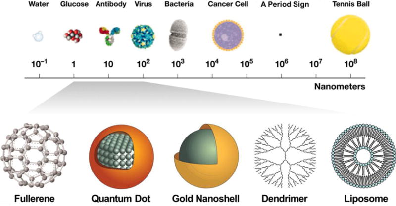
The sizes of nanomaterials are comparable to biomolecules and organisms. (Adapted from reference64).
Figure 2.
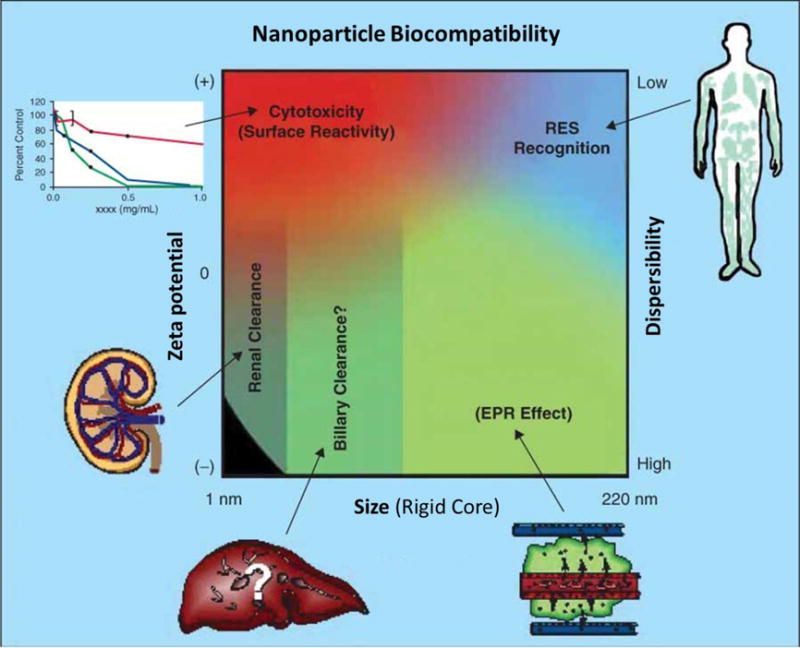
The physicochemical characteristics (effect of size, zeta-potential, and dispersibility) of nanoparticles influence its biocompatibility. Qualitative trends in relationships between the independent variables of size (neglecting contributions from attached coatings and biologics), zeta potential (surface charge), and dispersibility with the route of uptake and clearance (shown in green), cytotoxicity (red), and RES recognition (blue). (Adapted from reference65)
Figure 2 shows that nanoparticles with positive surface charge are often more toxic because of complications such as hemolysis and platelet aggregation. Positively charged nanoparticles can also have shorter circulation half-lives than negative and neutral counterparts66. Hydrophobic nanoparticles will be rapidly cleared by the reticuloendothelial system (RES)65.
While nanoparticles share a small size and high surface area, they differ in terms of the endogenous properties that govern their biocompatibility. The advantages and disadvantages as well as applications of various nanoparticles are presented in Table 1. Carbon nanotubes are pseudo one-dimensional nanomaterials that can penetrate through different cellular barriers. The high specific surface area and void in the center of carbon nanotubes can be used for drug delivery3–6. Graphene is a two-dimensional (2D) sheet of sp2-hybridized carbon atoms packed into a honeycomb lattice. The high surface area gives graphene a high adsorption capacity for molecules7–10.
Table 1.
The primary advantages, disadvantages, and main biological applications of common nanoparticle types. (CT: computerized tomography; MPI: magnetic particle imaging; MRI: magnetic resonance imaging; PAI: photoacoustic imaging76; PDT: photodynamic therapy; PTT: photothermal therapy; RES: reticuloendothelial system).
| Nanomaterials | Advantages | Disadvantages | Biological Applications |
|---|---|---|---|
| Carbon nanotubes3–6 | Extravasation, Small in one dimension |
Toxic in certain formats, Non-biodegradable |
Raman, PAI, Drug delivery |
| Graphene7–10 | High thermal conductivity, Large surface area Flexible |
Non-biodegradable, Poor dispersibility |
Biosensors, PTT, Drug delivery, Optical imaging |
| Liposomes11–14 | Excellent biocompatibility, Load both hydrophobic and hydrophilic cargos, Fuse with cells |
Unstable storage, Rapid leakage of hydrophilic drugs, Low encapsulation efficiency |
Ultrasound, Lipofection, Drug delivery |
| Dendrimers15–19 | Precisely controlled morphologies, Homogeneity, High ligand density, Controlled degradation |
Multistep synthesis, High cost |
Drug delivery, Gene delivery, Blood substitution |
| Polymer nanoparticles20–25, 77 | Biocompatibility, Wide variety, High encapsulation |
Unstable structure, Drug leakage |
Ultrasound, Drug delivery |
| DNA59–62 | Exquisite size control, Functional designs |
Unstable, | Drug delivery |
| Silica nanoparticles28–34 | Tunable morphologies, Easy surface modification, Biocompatible, Biodegradable |
Poor biodistribution | Ultrasound, Drug delivery, Define sentinel lymph nodes |
| Quantum dots36–39 | Tunable emission, Single excitation, Small, Good biodistribution |
Toxic components, Non-biodegradable |
Optical imaging, PTT |
| UCNPs40–44 | Narrow emission spectra, Long luminescence lifetime Chemically stable |
Low brightness, Size, surface, and laser power density dependent quantum yield |
Optical imaging, PTT, Photo-induced drug delivery, Biosensors |
| Superparamagnetic iron oxide nanoparticles45–49 | MRI T2-weighted contrast, Stable, Biodegradable |
Weak signal, High dose, RES accumulation |
MRI, MPI, Hyperthermia, Directing, Separation |
| Other metal oxide nanoparticles50–52 | Tunable morphology, Degradable |
Poor biocompatibility | Antimicrobial agents, Drug delivery |
| Noble metals nanoparticles54–58, 78 | Tunable, Stable, Inert, Thermally conductive, Plasmonic |
Weak signal, High dose, Poor biodistribution, Non-biodegradable, Low drug loading |
CT, PAI, PDT, PTT |
Liposomes are spheres composed of lipid bilayer similar to biological membranes. Liposomes have been used to load cargos such as therapeutic molecules, nucleic acids, and fluorocarbon gas to achieve drug delivery, lipofection, and ultrasound contrast agents.11–14 Dendrimers are highly branched polymers that can form nanoparticles with voids to load drugs and genes. Dendrimers can also be used as a blood substutite15–19. DNA origami utilizes the nanoscale folding of DNA and has been applied to drug delivery59–62. Quantum dots are luminescent zero-dimensional particles, and their photoluminescence can be manipulated to specific wavelengths by controlling the particle diameter69. They are commonly used in fluorescence/luminescence imaging36–39.
UCNPs are nanoparticles that absorb two or more incident photons of relatively low energy70. These are then converted into one emitted photon with higher energy. These nanoparticles usually contain transition metals and are used for bio-imaging40–44. Superparamagnetic iron oxide nanoparticles have also been widely used as MRI contrast agents and manipulators combined with magnetic fields45–49. Other commonly investigated metal oxides nanoparticles include titanium oxide, zinc oxide, and manganese oxide (MnO) nanoparticles50–52. Noble metal nanoparticles are usually nanoscale particles composed of gold and/or silver, and these have surface plasmon resonance (SPR) that can enhance the sensitivity of several spectroscopic measurements such as fluorescence, Raman scattering, and second harmonics71, 72. Other emerging nanomedicines include fullerenes73, nanoclays74, and micelles75.
1.3 Potential and challenges of nanomaterials in medicine
Nanomedicine based on the above nanomaterials has been reported to improve the medical imaging and treatment of various diseases, such as cancers79–82, degenerative diseases83, 84, heart disease85, 86, diabetes87, 88, and toxin detection89. Some nanomaterials are commercially available for their medical applications. For example, Abraxane, Doxil, and Megace ES are Food and Drug Administration (FDA)-approved nanotechnology-based drugs used to treat cancers80. Moreover, there are many nanomaterials that are currently in clinical trials. For instance, Cornell Dots (C-dots) are a nanoparticle-based diagnostic tool that is used for imaging tumors90 and currently in clinical trials. However, these commercial nanosystems have only one function.
Indeed, diagnosis and therapy are currently two separate steps. Multiple nanosystems are needed if each nanosystem can only perform one of those functions, but can results in problems with interference and dosage. First, nanosystems may interfere with each other causing unexpected side effects or decreasing the diagnostic and/or treatment efficacy. Second, using a higher dosage of materials increases the risk of toxicity. Therefore, developing multifunctional systems has a critical role in improving human health.
Multifunctional diagnostic and therapeutic incorporate several nanomaterials into one host material. This material must be compatible with a wide variety of functional molecules and/or nanoparticles. Silica nanoparticles are an excellent example for a host material because they demonstrate multi-functionality, biocompatibility, stability, and biodegradability.
1.4 Advantages of silica nanoparticles
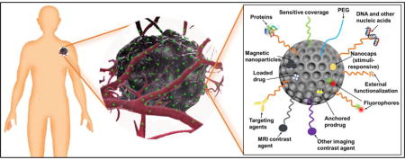
Silica nanoparticles have many advantages for medicine. First, the chemistry is easily tuned to create nanomaterials with defined sizes, shapes, and surface properties91. The easily modifiable chemistry in silica is essential for optimal biocompatibility and biodistribution28, 92. Silica nanoparticles synthesis has a history spanning over 60 years. Monodispersed amorphous silica nanoparticles were first synthesized by Kolbe in 195693 and was then improved by Stöber and Fink in 196894. Stöber’s method tunes the size of silica nanoparticles from tens of nanometers to several micrometers in diameter by changing the ratio of catalyst and precursor. In the early 1990s, “Template”-guided synthesis methods for mesoporous silica nanoparticles (MSNs) were reported by scientists from Japan and the Mobil corporation95–97. Examples of tunable silica nanomaterials include solid spheres93, 94, mesoporous particles95–98, mesoporous hollow spheres99, 100, rattle-typed spheres101, foam-like nanoparticles102, nanotubes103, mesoporous red blood cell-shaped nanoparticles31, etc. Figures 3A–H show examples of silica nanoparticles with different morphologies31. In addition, the surface of silica nanoparticles can be easily modified with functional molecules104 including spacers for colloidal stability105, antibodies for active targeting106, fluorophores for imaging107, magnetic nanoparticles108 for manipulation or MRI, gating molecules to stimulate drug release109, functional groups to tune surface charge32, and therapeutic agents110 (Figure 3I).
Figure 3.
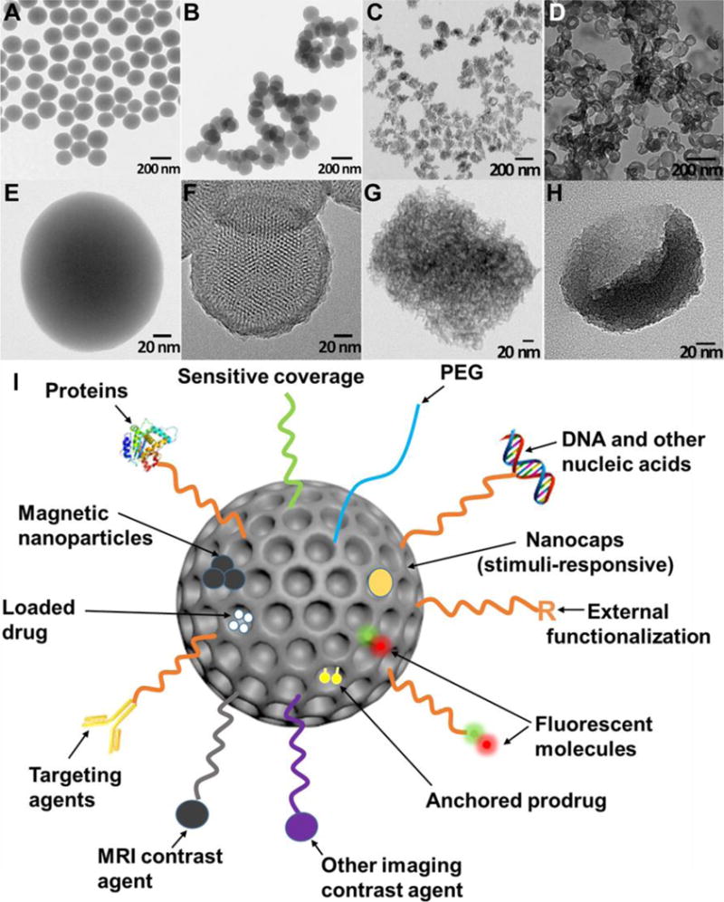
TEM images of solid Stöber silica nanoparticles (A, E), MCM-41 mesoporous silica nanoparticles (B, F), mesocellular foam silica nanoparticles (C, G), and exosome-like silica nanoparticles (D, H) (Adapted from reference31). (I) Multifunctionality of silica nanoparticles. PEG is polyethylene glycol.
Silica nanoparticles may have good biocompatibility because they degrade to nontoxic silicic acid in vivo111–113, and silicic acid is naturally found in many tissues and can be excreted from the body through urine112. However, the toxicity depends on their dosage114, crystallinity34, 114, 115, particle size91, 116, 117, surface properties116, 118, and administration route119, 120. Higher dosage increases the risk for toxicity. Crystal silica nanoparticles are toxic and cause silicosis115. But amorphous silica has been used as a food additive for decades because of its excellent biocompatibility34, 114. Smaller particles have been reported to be less biocompatible than larger ones91, 116, 117, possibly due to the increased specific surface area. However, this is still controversial121. Decreasing the surface hydroxyl groups increases the silica nanoparticles biocompatibility118. The size and surface properties of amorphous silica nanoparticles can easily be tuned to increase the biocompatibility. Nanoparticles administered orally have less immunotoxicity than intravenous, intraperitoneal, and subcutaneous route, but also lower bioavailability with less availability for the immune cells to interact with the nanoparticles121.
Silica nanoparticles are intrinsically stable, and moreover their degradability and circulation time can be tuned122–125. Generally, silica nanoparticles carry drug in their mesopores and release the drug through diffusion. Therefore, stability is important to enable the silica nanoparticles to be retained in the body and release the drug. This stability also guarantees no drug leakage from capped porous silica nanoparticles that release drug as a function of external stimuli124, 126. Though silica nanoparticles are usually cleared by the human body within a short time, surface modifications such as PEGylation can prolong the circulation period of silica nanoparticles127. On the other hand, imaging contrast agents need to be quickly cleared to decrease background signal and prevent interference with future scans. In this case, increasing the pore size of silica nanoparticles and doping them with metal ions can accelerate their degradation to get a short circulation time113, 125.
Finally, pure silica nanoparticles have intrinsic theranostic potentials stemming from high acoustic mismatch with most soft tissues. Also, silica nanoparticles can be customized to label cells and tissues and therefore increase their ultrasound contrast after transplantation31, 68, 128, 129. The therapeutic effects of silica nanoparticles result from their large surface area and porous structures. The large surface area provides plenty of conjugation sites or physical binding sites for therapeutic molecules130–132, and the pores in the silica nanoparticles can physically hold and protect cargo133–135.
In summary, silica nanoparticles are ideal for nanomedicine and biomaterials research due to their various morphologies, facile chemical modification, tunable pore size and porosity, biocompatibility, tunable stability and biodegradability, and theranostic potential.
2. Synthesis, modification, and integration of silica nanoparticles
2.1 Synthesis of silica nanoparticles
Silica nanoparticles can be prepared via bottom-up or top-down methods. Bottom-up synthesis usually involves catalyzed hydrolysis and condensation of silica sources94, 98. The top-down synthesis of silica nanoparticles includes electrochemical etching of silicon wafer and pyrolysis of quartz sand118, 136.
Bottom-up synthesis is very common in laboratory research because it is simple, safe, and can make various morphologies. Bottom-up synthesis typically uses an aqueous or ethanol based solvent, and this method usually involves silica sources, catalysts, and templates. The most prevalent silica source is an alkoxide of silicon scuh as tetraethyl orthosilicate (TEOS). The alkoxide first hydrolyzes and produces silicate species and alcohol (Equation 1). The silicates then condense and form Si-O-Si linkages (Equation 2). In addition, organosilanes such as aminopropyl-trimethoxysilane and mercaptopropyl-methoxysilane are usually used as co-precursors, which can introduce functional groups to the silica nanoparticles surface1.
| Equation 1 |
| Equation 2 |
R represents alkyl groups and is usually methyl or ethyl groups. The hydrolysis of silica sources can be catalyzed either by acids or bases. Under basic conditions, the polymerization and condensation of silicate species are reversible, which makes it easier to obtain homogenous silica products. On the contrary, highly acidic conditions lead to rapid hydrolysis and precipitation of silica particles. The production of silica nanoparticles can be accelerated by decreasing pH, but that often results in poly-disperse products98. Templates are used to generate porous structure in the silica nanoparticles. The most common templates are surfactants that form micelles in solvents and create mesopores that are smaller than 5 nm. This pore size is suitable for small molecule cargos. Larger pores are needed to load macromolecules and small nanoparticles such as quantum dots. To enlarge silica nanoparticles pores, polymers and pore expanding agents are normally used137. Interestingly, cells and organs can also be used as templates138, 139.
Top-down methods are more hazardous to implement because they require highly corrosive hydrofluoric acid (electrochemical etching) or high temperatures (>1500°C, pyrolysis)140. Moreover, tuning silica nanoparticles morphology is difficult using top-down methods. For example, fumed silica nanoparticles prepared by pyrolysis are nonporous and range in size from 5 to 50 nm. These nanoparticles are commonly used as light abrasives in toothpaste or as anticaking agents and desiccants. On the contrary, the silica nanoparticles obtained by electrochemical etching have an irregular 2D porous structure. The direct products from electrochemical etching are porous silicon stand-free films. To create porous silica nanoparticles, the silicon films are broken down by sonication and then oxidized136, 141.
2.2 Surface modification of silica nanoparticles
The surface of silica nanoparticles can be modified with polymer chains either chemically (by covalent bonding) or physically (by physisorption)142. Physical modification is usually reversible. It is not as common as chemical modification due to the instability of the non-covalent bond143.
Subsequent chemical modification is enabled by the silanol and siloxane groups on the silica. The number and form of the silanol groups changes as a function of synthesis route118. Colloidal silica nanoparticles are almost completely hydroxylated, and all silanols have hydrogen bonds. Fumed silica nanoparticles have much lower silanol contents—only about half of the surface has silanols. Approximately 10% of the silanols on fumed silica nanoparticle surfaces are isolated. Heat treatment can decrease the silanol content on both types of silica nanoparticles.118
Silanol groups are the main reason underlying the facile modification of silica nanoparticles. These groups can react with abundant and commercially available silane reagents. Silanes then introduce other functional groups onto the surface of silica nanoparticles. The most frequently used silanes have amine or sulfur groups at the end of an alkylsilane along with various PEG-silanes. Amine or thiol-ended groups offer a facile linker chemistry with commonly used linking moieties such as N-hydroxysuccinide (NHS) functionalized molecules, isothiocyanates, maleimides, etc106, 144. Both of these functional groups can also be used to tune the surface charge of the silica nanoparticles32, 145. Alkylsilanes are used for hydrophobic surface treatment and to increase the echogenicity of silica nanoparticles146. PEG-silanes graft PEG onto silica nanoparticles, improve the particles stability in biological fluids, and prolong the in vivo circulation time147, 148. Table 2 presents the most frequently used silanes for nanoparticle surface modification and their functions.
Table 2.
The most frequently used silanes used for surface modification on silica nanoparticles (NPs) and their functions.
| Silanes | Function Group | Application |
|---|---|---|
|
(3-aminopropyl)trimethoxysil ane (APTMS) (3-aminopropyl)triethoxysilan e (APTES) |
−NH2 | Reduced aggregation105, Fluorescent labeling144, Surface charge modification145, DNA binding and protection from enzymatic cleavage149 |
| (3-mercaptopropyl)-trimethox ysilane (MPTMS) | −SH | Conjugate with maleimides106, Thiol/disulfide exchange reactions to attach oligonucleotides150, Surface charge modification32, 151 |
| Polyethylene glycol-silane (PEG-silane) | −PEG | Increased circulation time152, Reduced aggregation and increase particle dispersity in aqueous solution127 |
| Alkylsilane | Alkyl chain | Hydrophobic coating153, Increase ultrasound contrast154 |
| Carboxyethylsilanetriol | −COOH | Functionalize silica NPs and provide reactive sites for amine155 |
| 3-trihydroxysilylpropyl methylphosphonate | −PO3− | Functionalize silica NPs and provide reactive sites for amine156 |
| (3-isocyanatopropyl)-triethox ysilane | −NCO | Functionalize silica NPs and provide reactive sites for amine157 |
2.3 Formulations/functions of silica in integrated nanoparticles
Silica mainly exists as a core, shell, or matrix for doping in integrated nanoparticles. Table 3 summarizes the major functions of silica as a function of its formulation in the nanoparticles along with relevant literature sources. The synthesis of nanoparticles with a silica core involves the preparation of silica nanoparticles followed by a multi-step modification106, 158, 159. The synthesis of the silica core is similar to the preparation of silica nanoparticles—mainly polymerization and condensation of silica sources98.
Table 3.
Functions of silica in integrated nanoparticles.
| Formulations | Function |
|---|---|
| Silica core | High dielectric constant enhances light absorption168, Therapeutic reservoir for drug delivery158,169,170, Increase ultrasound contrast129 |
| Silica shell | Facilitates functionalization of NPs surface168,171, Amplifies photoacoustic signal172, Therapeutic reservoir for drug delivery173, Enhances colloidal and chemical stability of the core174, Separates core from outside layer175, Decreases cytotoxicity of core160 |
| Silica matrix | Prevents photobleaching of fluorophores144, Decreases cytotoxicity113, 176, 177 |
Similarly, the core/silica shell structures are made via a multistep procedure160. Generally, the silica shell is formed by growing a layer of silica on the surfaces of other nanomaterials such as gold nanoparticles, gold nanorods, quantum dots, and iron oxide nanoparticles. The surfaces should have a significant chemical or electrostatic affinity for silica161, otherwise the surfaces need to be activated. For example, the surfaces of gold nanomaterials have a weak has and therefore stabilizers are typically used on the surface of gold to prevent coagulation. Therefore, the gold surface is usually treated with MPTMS before coating with silica162.
Doping functional ions, functional groups, and/or molecules into the silica matrix is another method to create multi-functional nanoparticles163, 164. There are two methods to dope silica nanoparticles. The first method is a one-pot sol-gel synthesis that mixes silica sources with a wide variety of organic dye molecules, metal ion chelators, or even iron oxide or quantum dots164. The other method is reverse microemulsion, which is suitable for doping hydrophobic organic dyes into silica nanoparticles165–167. This method involves creating a homogeneous mixture of water, oil, and surfactant molecules; the dye molecules often need to be modified to increase their affinity for silica165.
One big challenge for the translation of hybrid silica nanoparticles is simplified synthetic steps that integrate both cargo and carrier. It is currently difficult to achieve one-pot synthesis whereby the cargo is loaded into the nanoparticles as they are being synthetized. This is due to the multiple components involved—especially when sensitive therapeutic/diagnostic molecules are added. Thus, post-synthetic loading remains common to retain the biological activity of the sensitive molecular cargo. However, this method is time-consuming and inefficient, which is difficult to be used industrially. Future research efforts should design creative ways to solve this problem.
3. Integrated silica nanoparticles in nanomedicine
3.1 Theranostic and multimodal imageable silica nanoparticles
Theranostic and multimodal imageable nanoparticles are nanoparticles that act as both diagnostic and therapeutic agents. Theranostic nanoparticles are valuable tools for identifying and selecting patients followed by treating selected patients positively. Multimodal nanoparticle contrast agents combine the advantages of different imaging modalities.
In this context, a variety of diagnostic information can be obtained depending on the particle design. For example, theranostic medicines can provide insights into the availability of a molecular target in the tissue, the vascular permeability and retention of the molecule, the drug release from the particle, and the response of the target tissue178.
Nevertheless, the silica components in these integrated systems play various important roles in stabilizing and protecting the core nanoparticles or dopants. They offer multiple chemical modification methods and serve as a therapeutic reservoir to achieve target delivery and/or controlling release. For example, coupling fluorophores into silica nanoparticles can diminish the effect of fluorophore photobleaching. Peng et al. developed intracellular pH sensitive nanoparticles that can detect cellular pH from pH 4–7144. These nanoparticles are silica nanoparticles doped with two fluorophore sensors. Silica increases the stability and sensitivity of the fluorophores and allows for high quantification and measurement reversibility by diminishing photobleaching of the dyes.
Silica can also decrease the toxicity of nanoparticles that contain toxic components such as heavy metals. Doping functional elements such as lanthanide ions into silica is another useful strategy to make multifunctional nanoparticles. For example, gadolinium (Gd) is a commonly used MRI T1 contrast agent, but it is toxic due to its accumulation in tissues like brain, bone, and kidneys179. Silica nanoparticles doped with gadolinium not only improve the MRI contrast but also decrease the toxicity of Gd.
Rieter et al. added a paramagnetic monolayer of silylated Gd complex onto a luminescent [Ru(2,2′-bypyridine)3]Cl2 core by a water-in-oil reverse microemulsion method176. This nanoparticle offers fluorescent and MRI signals due to the [Ru(2,2′-bypyridine)3]Cl2 core and the Gd in the silica shell. The silica is also conjugated with diethylenetriaminetetraacetate (DTTA), which provides seven binding sites for Gd3+ ions to minimize the toxicity of nanoparticles owing to the leaching of Gd3+ centers. The nanoparticle is sufficiently small (<50 nm) to be endocytosed by monocyte cells and allows multimodal in vitro imaging of the cells. The authors are using this nanoparticle as target-specific contrast agents for optical and magnetic resonance (MR) imaging of rheumatoid arthritis in mice176.
Our group previously designed a multimodal silica nanoparticle which has a fluorescent, ultrasound, and MRI signal177. The ultrasound contrast can increase the contrast of the stem cells and guide the injection of stem cells, and the MRI signal is proportional to the cell numbers, which can be used to track the cell numbers after injection. The nanoparticle was prepared based on the Stöber method including fluorescein isothiocyanate (FITC)-conjugated organosilanes with TEOS; GdCl3 was used for Gd doping (Figure 4A). Silica produces ultrasound contrast because it has a high acoustic impedance mismatch with cells and soft tissues. Silica reflects more ultrasound, and thus the silica materials have more ultrasound signal than soft tissues in ultrasound images. The size of these nanoparticles can be tuned, and the ultrasound contrast of these nanoparticles is size dependent (Figure 4B–D). This nanoparticle is used to label and track stem cells to improve stem cell therapeutic efficacy.
Figure 4.
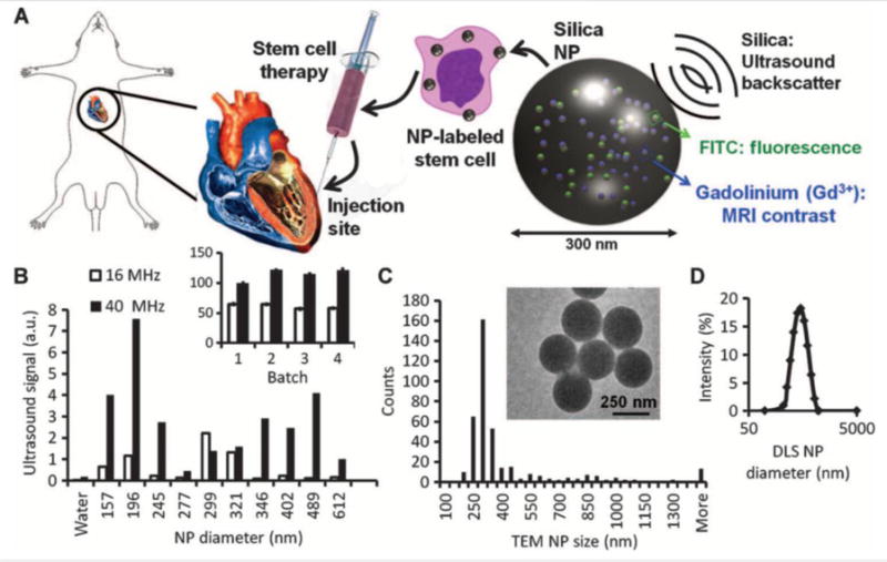
(A) Cardiac stem cell therapy uses human mesenchymal stem cells loaded ex vivo with nanoparticles, which consist of silica (SiO2) framework that backscatters ultrasound (black waves) and stabilizes Gd3+ and FITC fluorophores. (B) The ultrasound signals for 0.5 mg of different-sized NPs in an agarose phantom are shown at 40 and 16 MHz. Inset, batch-to-batch variability in ultrasound signal of 5 mg of NPs. (C) The size distribution within the 299-nm batch size selected from (B) had a mode size of 300 nm via TEM. Inset, TEM image of NPs. (D) Dynamic light scattering (DLS) of the 299-nm batch. Reproduced with permission177. Reprinted with permission from AAAS.
Later work developed a theranostic system using this nanoparticle by introducing pores into the silica nanoparticle113. The nanoparticles retain the multimodal imaging signals–ultrasound, MRI, and fluorescence (Figure 5A–E). Sectioning transmission electron microscopy (TEM) images show these nanoparticles are located in the cytoplasm of the cell (Figure 5F–H). Moreover, the pores are used to load a prosurvival agent for stem cells and slowly release the insulin-like growth factor (IGF) inside cells (Figure 6A, B). This system increases cell survival up to 40% (p<0.05) versus unlabeled cells under in vitro serum-free culture conditions (Figure 6C).
Figure 5.
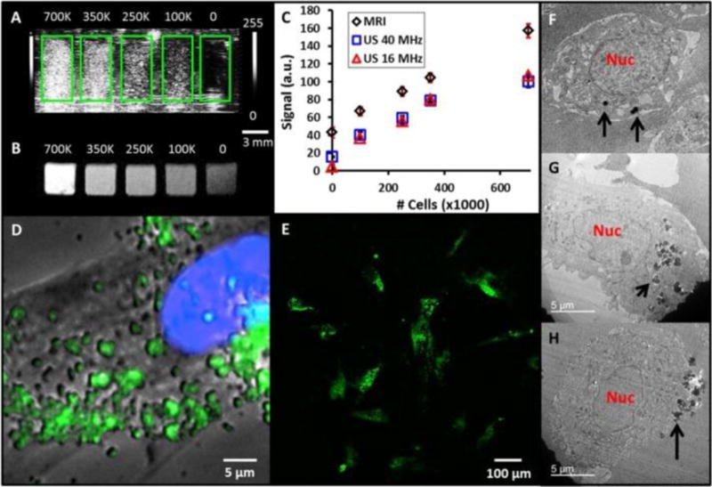
(A) Coronal view of 40 MHz ultrasound imaging of decreasing number of MSNs-labeled mesenchymal stem cells (MSCs). Green boxes outline the boundaries of wells in the phantom. (B) Transverse view from T1-weighted MRI of the same cell sample. Scale bar and intensity bar to the right of A apply to both panels. (C) Dose response curves for increasing numbers of cells shows linear relationships at R2 >0.97 for both MRI and ultrasound (US). (D) Epifluoresence microscopy with MSCs nucleus in blue and MSNs fluorescently tagged in green. Punctate areas are seen indicating endosomal accumulation of MSNs. (E) Confocal microscopy image indicating that the MSNs are located both on the cell periphery and interior. Panels (F-H) are three representative TEM images of MSCs labeled with MSNs. Note that the MSNs are located both on the cell periphery (F, H) and interior (G). Nuc: nucleus; Black arrows: MSNs. Reproduced with permission113.
Figure 6.
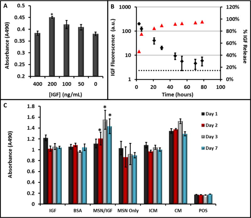
(A) The ability of IGF to increase cell survival under serum-free conditions was studied at increasing concentrations of IGF—values of 200 ng/mL were optimal and significantly (p<0.001) increased viability 25% relative to untreated cells. (B) The release kinetics of IGF from the MSNs showed sustained release up to 48 hours. Here, red triangles are the percent of total release (right axis) and the black diamonds are absolute fluorescence from free IGF. (C) Sustained release of (IGF) from porous MSNs increases cell survival under serum-free media challenge as studied with MTS assay. The * indicates that the IGF-NPs had a statistically significant increase in viability versus incomplete media (p<0.05) and free IGF (p<0.05). IGF: Free IGF; BSA: Bovine Serum Albumin Control; MSNs/IGF: MSNs loaded with IGF; ICM: Incomplete Media (serum-free); CM: Complete Media. Error bars represent the standard error. Reproduced with permission113.
Sweeney et al. used a similar silica nanoparticle doped with gadolinium oxide and conjugated with tetramethylrhodamine-isothiocyanate (TRITC) to improve real-time monitoring and staging of mouse bladder cancer models180. They injected murine flanks with MB49 cancer cells, and then injected silica nanoparticles to examine differences in MRI signal between tumors and bladder epithelium. The integrated silica nanoparticles enhanced both T1 and T2 weighted MRI signals in the tumors, allowing detailed in vivo evaluations (Figure 7). The localization of particles helped delineate the tumor’s edges, which are usually difficult to detect. This system can potentially be used for theranostic purposes, as therapeutic carriers for anticancer agents, and diagnostic tools for tumor visualization.
Figure 7.
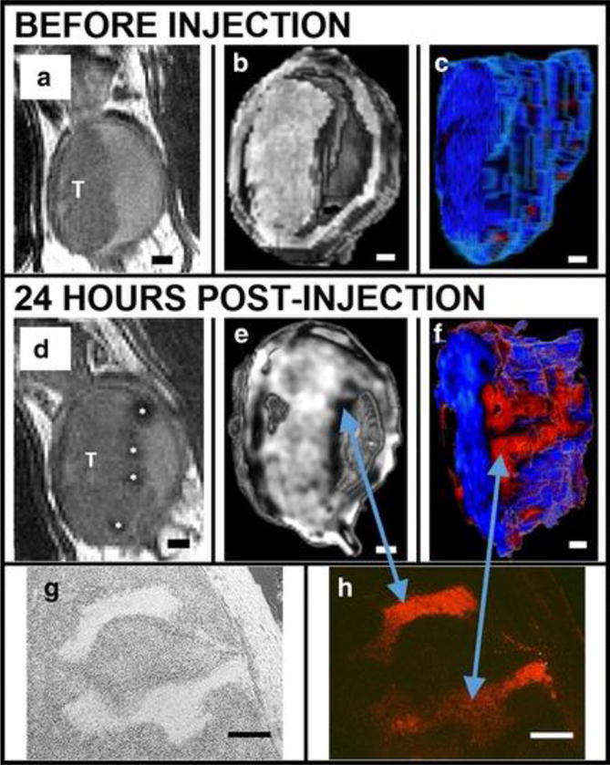
MSNs bind preferentially to bladder cancer cells relative to normal bladder epithelia in vivo as shown in a series of renderings of T2-weighted MRI scans acquired before (A-C) and after (D-F) intravascular instillation of Gd2O3–TRITC–MSN. (A, D) 2D grayscale view, T: tumor. (B, E) Three-dimensional (3D) rendering images. (C, F) The tumor is segmented and rendered with a pseudo color map. Finger-like projections are revealed which are not observed before the injection of particles (C). Histology confirms anatomical observations and particle penetrations in the structures within the tumor: bright field (G) and fluorescent microscopy (H). Scale bars 1 mm (A-F); 250 μm (G, H). Reproduced with permission from Ref180.
Lin et al. developed a theranostic targeting mesoporous silica nanoparticle with multiple imaging modalities by doping and surface conjugation181. The nanoparticles are doped with europium (Eu) and Gd ions. These ions introduce fluorescence and magnetism to the mesoporous structure, and thus the nanoparticles can be used as a fluorescent tool. The MRI indicates the location and size of the tumor. The doped nanoparticle is then conjugated with the anticancer drug camptothecin (CPT) by disulfide bonds. This disulfide bond can be cleaved by a high concentration of intracellular glutathione for intracellular controlled release. Moreover, the surface of the nanoparticle is modified with folic acid, which can be used to target most human cancer cells. In vitro and in vivo studies show that these integrated silica nanoparticles can target, image, and destroy the tumors in mice.
Silica is also highly useful for assistance in functionalizing nanoparticles. Fluorescent and radio-opaque nanoparticles can be used for CT, MRI, and diffuse optical tomography171. They have a silica core that is doped with tris(2,2′-bipyridyl) dichlororuthenium(II) hexahydrate. The core is surrounded by a layer of n-(trimethoxysilyl-propyl)ethyldiamine tri-acetic acid trisodium salt that traps paramagnetic Gd3+ ions. Finally, the particles are wrapped by an additional silica shell layer containing amine groups on the surface that can be used for functionalization. This multimodal (optical, radiology, CT, and MRI) contrast agent can help in the preoperative diagnosis and in the intraoperative surgical resection of tumors or other surgical lesions171.
Mesoporous silica-coated MnO nanoparticles also show great potential as MRI contrast agents for cell tracking50. These nanoparticles have a MnO/SiO2 core shell structure, and the nanoparticles are named as HMnO@mSiO2 nanoparticles where the symbol @ usually means inside. (Figure 8A, B). The innate r1 relaxivity of MnO provides the MRI signal of the nanoparticle (Figure 8C, D). The silica increases the biocompatibility of MnO core. This nanoparticle can label MSCs in vivo and shows intense signals (Figure 8E, F). Moreover, the MRI signal can be detectable 14 days after the injection (Figure 8F).
Figure 8.
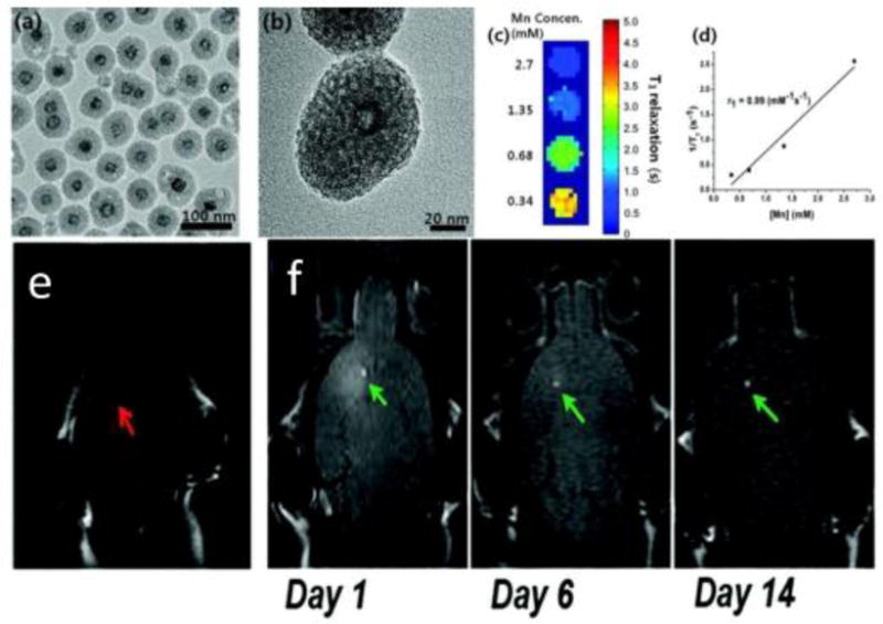
(A) TEM image. (B) HRTEM image of a single nanoparticle. (C) T1 map of HMnO@mSiO2 nanoparticles suspended in water at 11.7 T. (D) Plot of 1/T1 versus Mn concentration. The slope indicates the specific relaxivity (r1). (E) In vivo MRI shows no hyperintense signal (red arrow) was detected in mouse transplanted with unlabeled MSCs. (F) Hyperintense signals (green arrows) were detected in mouse transplanted with HMnO@mSiO2-labeled MSCs and were still detectable 14 days after the injection. Reproduced with permission from Ref50.
The MnO/SiO2 core shell structure can also be used for a theranostic and multimodal imaging system. Choi et al. embedded MnO/SiO2 core/shell nanoparticles into porous poly(propylene fumarate) (PPF) scaffolds and used the MRI signal change to monitor the release of nanoparticles from the PPF scaffold surface. The anti-cancer drug doxorubicin (DOX) was loaded on the surface of the MnO/SiO2 NPs by electrostatic interaction between the drug with the negatively charged porous silica surface182. Additionally, the porous silica shell can also enhance the water-dispersibility of the core and minimize the leakage of the core ions. Moreover, silica shell prevents the aggregation between MnO nanocores and therefore increases the dispersity of MnO nanocores.
Monaco et al. synthesized a core-shell Fe3O4@SiO2@Au nanosystem coated with 11-(4-mercaptobenzamido) undecanoate, poly(lactic-co-glycolic acid)-b-PEG-NH2, and folic acid183. This nanosystem provides in vivo targeting capabilities and MRI-PA dual imaging signals. The combination of MRI and PAI offer mutual benefits—it overcame the depth and resolution limits of PAI and the temporal resolution of MRI. The MRI signal is produced by iron oxide while the PA signal is produced by the gold shell. The multilayer nanoparticles are then embedded in the so-called polymeric micelles to improve their biocompatibility183. The researchers then conjugated folic acid on the polymeric micelle surface to get a water-soluble nanocarrier that actively targets folate receptors that are often overexpressed in solid tumors. Their final system is highly biocompatible and can be manipulated to build other targetable nanostructures.
Mesoporous silica shells can also improve the performance of gold nanorods (AuNRs) in biomedical applications. AuNRs show great potential in multiple imaging modalities and therapies including CT, PA, PDT, and PTT. However, AuNRs have a low drug loading capacity and suffer from clustering, aggregation, and shape deformation. Zhang et al. fabricated a mesoporous silica shell coated AuNRs and loaded doxorubicin to the nanoparticle. These particles enable imaging, chemotherapeutics, and hyperthermia within a single nanoparticle platform for cancer treatments (Figure 8A)184. The silica forms a protective layer outside the AuNRs and prevents them from aggregation (Figure 8B, C). The silica-coated nanorod showed stable surface plasmon resonance (Figure 8D). In addition, the release of doxorubicin from the nanoparticle can control the pH and near infra-red laser (Figure 8E). Moreover, the system can kill cancer cells by photothermal therapy. These properties make this nanoplatform a potential candidate for new therapeutic modalities such as image-guided drug delivery, hyperthermia, and combination therapy.
Figure 8.
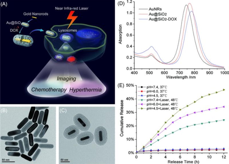
(A) Schematic illustration of mesoporous silica-coated gold nanorods (Au@SiO2) as a novel multifunctional theranostic platform for cancer treatment. TEM images of (B) AuNRs and (C) Au@SiO2; (D) extinction spectra of AuNRs, Au@SiO2, and Au@SiO2–DOX, and (E) DOX release profiles from Au@SiO2–DOX with and without near infrared (NIR) laser irradiation at different pH. Reproduced with permission from Ref184.
Kircher et. al. synthesized novel nanoparticles for MRI, photoacoustic, and Raman imaging in brain tumors185. These triple-modality contrast agents are used to delineat detailed brain tumor margins to remove more tumor tissue. These contrast agents are created with a 60-nm gold core, a Raman-active layer, a silica shell, and a gadolinium coating (Figure 9A, B). These nanoparticles are highly sensitive and detectable in the picomolar range for all three modalities (Figure 9C–E). In addition, it was shown that particles injected intravenously accumulated within the brain tumor but not in the adjacent healthy tissue (Figure 10), which allows for a noninvasive brain tumor delineation. This nanoparticle-based triple-modality contrast agent offers more accurate brain tumor imaging and resection.
Figure 9.
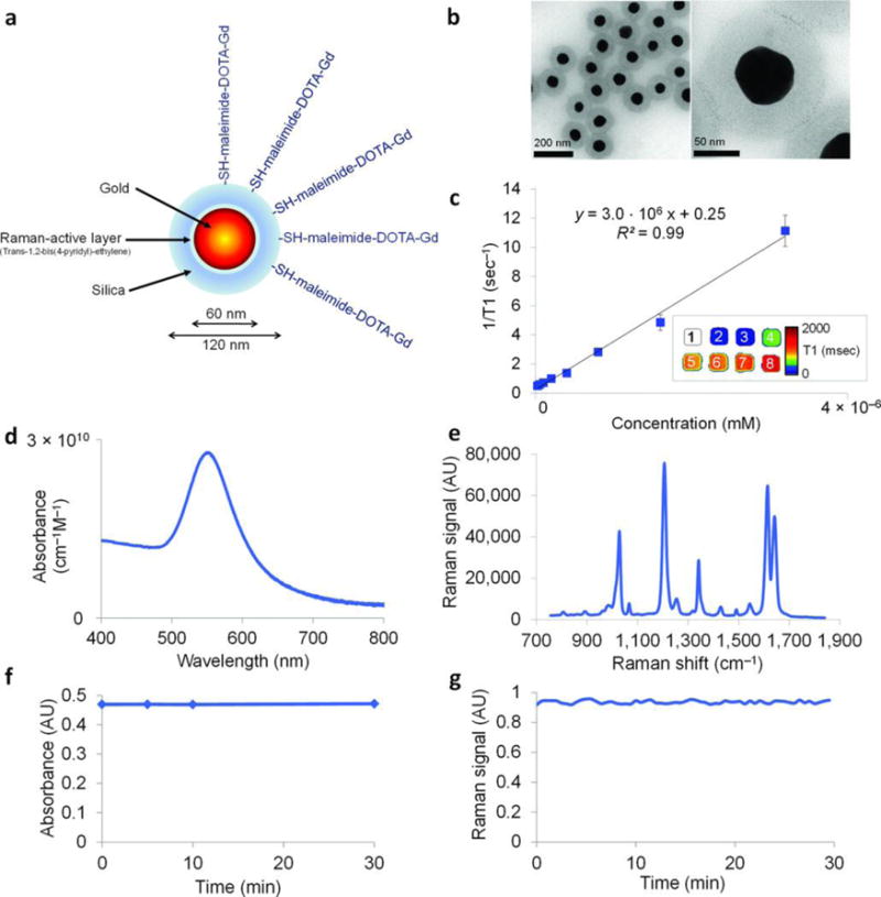
Characterization of the NPs. (A) Simplified diagram: A 60 nm gold core is surrounded by a thin Raman active layer that is protected by a 30 nm silica coating. The silica coating was further functionalized with maleimide-DOTA-Gd, which was conjugated to the thiol group on the silica. DOTA, tetraazacyclododecane-1,4,7,10-tetraacetic acid, is a chelator. (B) Transmission electron microscopy images of NPs. (C) Particle relaxivity derived from T1 maps of probe dilutions in MRI phantoms. Data represent mean of two separate phantoms containing separate probe conjugations. Inset: T1 map of a MRI phantom containing NPs at concentrations ranging from 3.2 nM (1) to 25 pM (8). (D) Optical absorbance of NPs. (E) Raman spectrum of NPs with characteristic peaks at 1,021 cm−1, 1,204 cm−1, 1,340 cm−1, 1,614 cm−1, and 1,638 cm−1. (F, G) During 30 min of continuous laser irradiation, the optical absorbance (F) and the Raman signal (G) remained constant. Adapted by permission from Macmillan Publishers Ltd: [Nature Medicine]185, copyright (2012).
Figure 10.
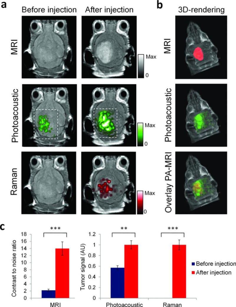
Triple-modality detection of brain tumors in living mice with integrated nanoparticles. Three weeks after orthotopic inoculation, tumor-bearing mice (n = 4) were injected intravenously with the NPs. Photoacoustic, Raman, and MRI images of the brain (skin and skull intact) were acquired before and 2 h, 3 h, and 4 h after injection, respectively. (A) 2D axial MRI, photoacoustic, and Raman images. The post-injection images of all three modalities demonstrated clear tumor visualization. The photoacoustic and Raman images were co-registered with the MR image, demonstrating good co-localization between the three modalities. (B) 3D rendering of MR images with the tumor segmented (red; top); overlay of 3D photoacoustic images (green) over MRI (middle); and overlay of MRI, segmented tumor and photoacoustic image (bottom) showing good co-localization of the photoacoustic signal with the tumor. (C) Quantification of signal in the tumor shows significant increase in MRI, photoacoustic and Raman signals before versus after the injection (*** indicates P < 0.001, ** indicates P < 0.01). Adapted by permission from Macmillan Publishers Ltd: [Nature Medicine]185, copyright (2012).
Other than the functions mentioned above, Chen et al. also found that the silica shell can amplify the photoacoustic intensity of gold nanorods172. The group studied the relationship between photoacoustic signals and heat transfer properties in silica coated AuNRs. They found that the additional silica layer acted as a signal amplifier by reducing interfacial heat resistance between gold and a range of solvents (Figure 11). The addition of a silica layer 0-20 nm thick increased photoacoustic signal by up to 3-fold, peaking at 20 nm thickness. The addition of a silica layer to AuNRs appears to be a beneficial way to increase their utility as contrast agents for PAI.
Figure 11.
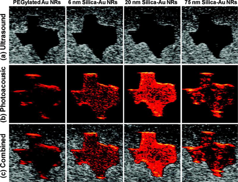
(A) Ultrasound, (B) photoacoustic, and (C) combined ultrasound and photoacoustic images (top to bottom) of inclusions containing PEGylated AuNRs and gold−silica core−shell nanorods with 6 nm silica coating, 20 nm silica coating, and 75 nm silica coating (left to right). Each image covers a 6 mm by 6 mm field of view. Reproduced with permission from Ref172. Copyright (2011) American Chemical Society.
3.2 Monitoring the release of therapeutic molecules
The real-time monitoring capabilities of molecules can provide an abundance of physiological and pathological information of the patients. Theranostic devices with integrated real-time monitoring abilities are emerging and offer more feedback on treatment. Integrated silica nanoparticles also show great potential in the field for real-time monitoring of molecules.
The silica component is an ideal cargo carrier. In 2005, Gruenhagen et al. monitored adenosine triphosphate (ATP) release from MCM-41 silica nanoparticles186. ATP was used as a model cargo and the release mechanism was studied through the use of ATP-activated luciferase, which produces bioluminescent signal with ATP exposure. Due to the capability of real-time monitoring for cargos during release, the authors found the release kinetics of encapsulated molecules can be controlled by changing the capping molecules.
Lai et al. (2013) reported a versatile fluorescence resonance energy transfer (FRET)-based drug delivery system110. These nanosystems consist of a coumarin-labeled cysteine tethered mesoporous silica nanoparticles as the drug carrier and a FITC-β-cyclodextrin (CD) as redox-responsive molecular gate blocking the pores. A FRET donor-acceptor pair of coumarin and FITC was integrated within the pore-unlocking event (Figure 12A). The presence of glutathione (GSH) in the environment of the particle provokes a redox response, unblocking the particle’s pores and releasing the encapsulated drugs. The extent of drug-release can be controlled by the ratio of FITC-β-CD to GSH and monitored by pathological cell viability and FRET signals (Figure 12B).
Figure 12.
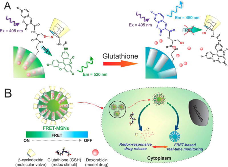
Schematic representation of the redox responsive FRET-MSNs. (A) The coumarin-labeled cysteine on the surface of the FRET-MSNs acts as a donor and the FITC-β-CD acts as an acceptor thereby forming a FRET system when the disulfide bond is intact (left). The disulfide bond is cleaved in the presence of redox stimuli and then the molecular valve FITC-β-CD is removed from the surface of the MSNs. Thereby the FRET between coumarin and FITC is abolished. (B) The drug delivery is triggered by glutathione, rich in the cytoplasm of cancer cells. Simultaneously, change of FRET signal report the uncaging event and estimate the dosing amount of drug. Figure 1A is a magnified representation of Figure 1B, indicating the FRET system. Reproduced with permission from Ref110. Copyright (2013) American Chemical Society.
Lai et al. developed a polypeptide-wrapped mesoporous silica coated multicolor up-conversion nanoparticle (UCNP@MSN) as a drug delivery system. This is advantageous because the drug release can be monitored in real-time187. They functionalized the system with zinc-dipicolylamine analogue (TDPA-Zn2+) and wrapped it with polypeptides to entrap the loaded drug–DOX. The TDPA-Zn2+ and polypeptide layer caused DOX to quench the ultraviolet (UV) emission upconverted from incoming NIR by the upconversion nanoparticles. ATP displaced the peptides because it has a higher binding affinity with TDPA-Zn2+. When ATP displaced the peptides, DOX was released through the open pores of the particles (Figure 13). The release can then be monitored through ratiometric changes in luminescence resonance energy transfer (LRET). The authors also showed that this system could be further functionalized with receptors like folic acids to distinguish different diseases.
Figure 13.
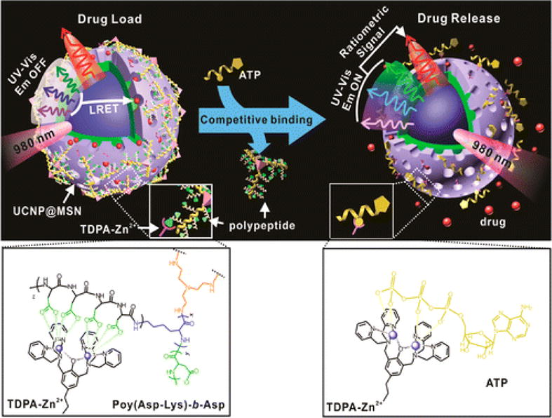
Schematic representation of the real-time monitoring of ATP-responsive drug release from polypeptide wrapped TDPA-Zn2+-UCNP@MSNs. Small molecule drugs were entrapped within the mesopores of the silica shell on the nanoparticle by branched polypeptide capping the pores through a multivalent interaction between the oligo-aspartate side chain in the polypeptide and the TDPA-Zn2+ complex on nanoparticles surface. The UV–visible emission from the multicolor UCNP under 980 nm excitation was quenched because of the LRET between the loaded drugs and the UCNP. The addition of small molecular nucleoside-polyphosphates such as ATP led to a competitive binding of ATP to the TDPA-Zn2+ complex, which displaced the surface bound compact polypeptide because of the high binding affinity of ATP to the metallic complex. The drug release was accompanied with an enhancement in the UV–visible emission of UCNP, which allows for real-time monitoring of the drug release via a ratiometric signal using the NIR emission of UCNP as an internal reference. Reprinted with permission from Ref187. Copyright (2015) American Chemical Society.
Liu et al. synthesized an NIR-triggered nanosensor that monitors drug-release by using upconverted luminescence and MRI simultaneously188. The nanosensor is composed of UCNPs surrounded by a mesoporous silica shell as well as doxorubicin and azobenzene to create a FRET donor-acceptor pair with UCNP (Figure 14). They found that under NIR exposure, drugs loaded into the particles were released, which led to a steady increase in MRI and upconverted luminescence signals. DOX quenched the upconverted emission from UCNPs, and its release increased the upconverted luminescence signal intensity. The loaded drug also made it less likely for water molecules to bond with Gd3+ ions. When DOX was released, water from the surrounding environment diffused into the particle and interacted with Gd3+. This increased the T1 MRI signal intensity.
Figure 14.
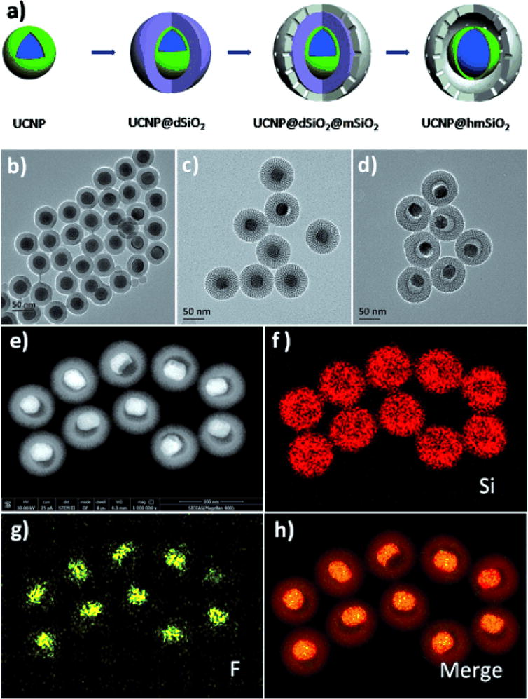
(A) The formation process of the nanoparticles. (B-D) TEM images of (B) UCNP@dSiO2, (C) UCNP@dSiO2@mSiO2, and (D) UCNP@hmSiO2. (E-H) STEM images and corresponding elemental (F, Si) mappings of UCNP@hmSiO2. Reproduced with permission from Ref188.
The silica component can also act as fixative for small molecules to offer contrast for monitored drugs. Wang et al. conjugated Stöber silica nanoparticles with methylene blue to monitor the blood concentration of heparin in real time32. Methylene blue is an FDA approved dye and it shows thermal expansion when it absorbs infrared light, which is also known as photoacoustic signal. The authors showed that heparin could increase the photoacoustic signal of methylene blue, and moreover, the signal increase is proportional to the concentration of heparin within the clinical dosage range. Silica nanoparticles were used to immobilize the methylene blue and prevent this dye from diffusing into the circulation (Figure 15A). Silica adsorbs methylene blue through electrostatic forces, and the surface charge of the silica nanoparticles affects the sensitivity of detection. Thiol modified silica nanoparticles are more sensitive than non-modified ones (Figure 15B, C). PAI is based on ultrasound imaging. PAI inherits the real-time imaging performance and the signal is stable over time (Figure 15D). Therefore, this method can monitor the heparin concentration changes without waiting for long time. This system can also detect low molecular weight heparin, which is not detectable by the conventional method—activated partial thromboplastin time (aPTT).
Figure 15.
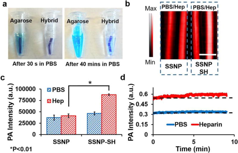
Optimization of material for a heparin-responsive catheter. (A) Methylene blue in agarose was not stable with more than 40% methylene blue release in PBS after 40 min. The addition of nanoparticles for an integration reduced this release to less than 10%. (B) Photoacoustic images of methylene blue loaded on as-made silica nanoparticles (SSNP; −23 mV) and methylene blue loaded on thiol-coated silica nanoparticles (SSNP-SH; −15 mV). Both were treated with PBS and heparin (Hep) but only the thiol-coated nanoparticles were responsive to heparin. The lower ζ-potential facilitated the photoacoustic signal increase. (C) Methylene blue-loaded SSNP-SH treated with heparin offers significantly more signal than SSNP-SH treated with PBS or SSNP. (D) The nanoparticle/agar material was treated with PBS or 10 U/mL heparin and imaged at 680 nm for 9 min with no decrease in signal. Reproduced with permission from Ref32. Copyright (2016) American Chemical Society.
Though the real-time monitoring capabilities of molecules can provide abundant of physiological and pathological information of the patients as well as feedback for treatments, the development of such devices is still in its nascent stage because of the limitations of real-time imaging modalities. Therefore, more efforts are needed for real-time imaging modalities.
4. Conclusions and prospectives
Silica is critical for integrated nanoparticles and offers great potential in theranostic, multimodal imaging, and real-time monitoring for molecules. Silica nanoparticles are easily made and tuned to various morphologies. They also show great biocompatibility and tunable degradability. Silica nanoparticles themselves can be used for drug delivery and ultrasound imaging contrast agents. Moreover, silica nanoparticles can be easily combined with other inorganic and/or organic components, which offers more features. Integrated silica-based nanoparticles can be used in nuclear imaging, MRI, radiography, optical imaging, ultrasound imaging, and magnetic particle imaging. The integrated particles can also be used in target delivery, controlled release, radiation therapy, hyperthermia therapy, photodynamic therapy, and immunotherapy. Extensive research has shown the great potential of integrated silica nanoparticles in theranostic and multimodal imaging.
Despite the huge number of studies on silica-based integrated nanoparticles for applications in bio-imaging and drug delivery, they have not made a significant impact in the clinic yet. The only silica-based integrated nanoparticle close to FDA approval are C-dots, which exhibit positron emission tomography (PET) and optical dual-modality imaging189. More studies are needed to improve their colloidal stability, optimize biodistribution, and customize biodegradation to promote the translation of these nanomedicines. Moreover, similar to all the other nanomedicine systems, increasing the targetability of integrated silica nanoparticles is critical to their translation with respect to manufacturing, cost, toxicity, and imaging and therapeutic efficacy—targetability of nanoparticles affects the actual drug dose at the desired location190.
We have summarized recent work that used integrated silica nanoparticles to monitor biomolecules. However, most of the systems are based on fluorescence, which is limited for in vivo and clinical study because of poor penetration depth of light. Therefore, developing new real-time imaging modalities with high penetration depth is necessary. Photoacoustic imaging is an emerging technique with both real-time capability and increased penetration depth191. However, the field is still premature due to the lack of designs for combining photoacoustic contrast agents with other functional materials. We expect that more integrated nano-designs will be studied to offer theranostic systems that also provide real-time feedback in vivo.
Acknowledgments
The authors would like to the National Institutes of Health grants R00 HL117048 and DP2 HL137187. We also acknowledge J. Lemaster for the help on the revision.
Footnotes
Publisher's Disclaimer: This is a PDF file of an unedited manuscript that has been accepted for publication. As a service to our customers we are providing this early version of the manuscript. The manuscript will undergo copyediting, typesetting, and review of the resulting proof before it is published in its final citable form. Please note that during the production process errors may be discovered which could affect the content, and all legal disclaimers that apply to the journal pertain.
References
- 1.Xie J, Lee S, Chen X. Advanced drug delivery reviews. 2010;62(11):1064–1079. doi: 10.1016/j.addr.2010.07.009. [DOI] [PMC free article] [PubMed] [Google Scholar]
- 2.Chen F, Zhao E, Kim T, Wang JX, Hableel G, Reardon PJT, Ananthakrishna SJ, Wang TY, Arconada-Alvarez S, Knowles JC, Jokerst JV. ACS Appl Mater Interfaces. 2017;9(18):15566–15576. doi: 10.1021/acsami.7b04181. [DOI] [PMC free article] [PubMed] [Google Scholar]
- 3.Liu Z, Tabakman S, Welsher K, Dai H. Nano Res. 2009;2(2):85–120. doi: 10.1007/s12274-009-9009-8. [DOI] [PMC free article] [PubMed] [Google Scholar]
- 4.Kostarelos K, Lacerda L, Pastorin G, Wu W, Sebastien Wieckowski, Luangsivilay J, Godefroy S, Pantarotto D, Briand J-P, Muller S, Prato M, Bianco A. Nat Nano. 2007;2(2):108–113. doi: 10.1038/nnano.2006.209. [DOI] [PubMed] [Google Scholar]
- 5.Yang S-T, Guo W, Lin Y, Deng X-Y, Wang H-F, Sun H-F, Liu Y-F, Wang X, Wang W, Chen M, Huang Y-P, Sun YP. The Journal of Physical Chemistry C. 2007;111(48):17761–17764. [Google Scholar]
- 6.Lu F, Gu L, Meziani MJ, Wang X, Luo PG, Veca LM, Cao L, Sun YP. Advanced Materials. 2009;21(2):139–152. [Google Scholar]
- 7.Mao HY, Laurent S, Chen W, Akhavan O, Imani M, Ashkarran AA, Mahmoudi M. Chem Rev. 2013;113(5):3407–3424. doi: 10.1021/cr300335p. [DOI] [PubMed] [Google Scholar]
- 8.He Q, Kiesewetter DO, Qu Y, Fu X, Fan J, Huang P, Liu Y, Zhu G, Liu Y, Qian Z, Chen X. Advanced Materials. 2015;27(42):6741–6746. doi: 10.1002/adma.201502762. [DOI] [PMC free article] [PubMed] [Google Scholar]
- 9.Feng L, Liu Z. Nanomedicine. 2011;6(2):317–324. doi: 10.2217/nnm.10.158. [DOI] [PubMed] [Google Scholar]
- 10.Zhang Y, Petibone D, Xu Y, Mahmood M, Karmakar A, Casciano D, Ali S, Biris AS. Drug metabolism reviews. 2014;46(2):232–246. doi: 10.3109/03602532.2014.883406. [DOI] [PubMed] [Google Scholar]
- 11.Huang SK, Stauffer PR, Hong KL, Guo JWH, Phillips TL, Huang A, Papahadjopoulos D. Cancer Res. 1994;54(8):2186–2191. [PubMed] [Google Scholar]
- 12.Kong G, Anyarambhatla G, Petros WP, Braun RD, Colvin OM, Needham D, Dewhirst MW. Cancer Res. 2000;60(24):6950–6957. [PubMed] [Google Scholar]
- 13.Torchilin VP. Nat Rev Drug Discov. 2005;4(2):145–160. doi: 10.1038/nrd1632. [DOI] [PubMed] [Google Scholar]
- 14.Weng KC, Noble CO, Papahadjopoulos-Sternberg B, Chen FF, Drummond DC, Kirpotin DB, Wang DH, Hom YK, Hann B, Park JW. Nano Lett. 2008;8(9):2851–2857. doi: 10.1021/nl801488u. [DOI] [PubMed] [Google Scholar]
- 15.Kukowska-Latallo JF, Bielinska AU, Johnson J, Spindler R, Tomalia DA, Baker JR. Proceedings of the National Academy of Sciences. 1996;93(10):4897–4902. doi: 10.1073/pnas.93.10.4897. [DOI] [PMC free article] [PubMed] [Google Scholar]
- 16.Gillies ER, Fréchet JMJ. Drug Discov Today. 2005;10(1):35–43. 17. doi: 10.1016/S1359-6446(04)03276-3. [DOI] [PubMed] [Google Scholar]
- 17.Svenson S, Tomalia DA. Advanced Drug Delivery Reviews. 2012;64(Supplement):102–115. doi: 10.1016/j.addr.2005.09.018. [DOI] [PubMed] [Google Scholar]
- 18.Lee CC, MacKay JA, Frechet JMJ, Szoka FC. Nat Biotech. 2005;23(12):1517–1526. doi: 10.1038/nbt1171. [DOI] [PubMed] [Google Scholar]
- 19.Tomalia DA, Naylor AM, Goddard WA. Angewandte Chemie International Edition in English. 1990;29(2):138–175. [Google Scholar]
- 20.Alexis F, Pridgen E, Molnar LK, Farokhzad OC. Molecular Pharmaceutics. 2008;5(4):505–515. doi: 10.1021/mp800051m. [DOI] [PMC free article] [PubMed] [Google Scholar]
- 21.Pinto Reis C, Neufeld RJ, Ribeiro AJ, Veiga F. Nanomedicine: Nanotechnology, Biology and Medicine. 2006;2(1):8–21. doi: 10.1016/j.nano.2005.12.003. [DOI] [PubMed] [Google Scholar]
- 22.Kumari A, Yadav SK, Yadav SC. Colloids and Surfaces B: Biointerfaces. 2010;75(1):1–18. doi: 10.1016/j.colsurfb.2009.09.001. [DOI] [PubMed] [Google Scholar]
- 23.Owens DE, III, Peppas NA. International Journal of Pharmaceutics. 2006;307(1):93–102. doi: 10.1016/j.ijpharm.2005.10.010. [DOI] [PubMed] [Google Scholar]
- 24.Soppimath KS, Aminabhavi TM, Kulkarni AR, Rudzinski WE. Journal of Controlled Release. 2001;70(1–2):1–20. doi: 10.1016/s0168-3659(00)00339-4. [DOI] [PubMed] [Google Scholar]
- 25.Galaev IY, Mattiasson B. Trends in Biotechnology. 1999;17(8):335–340. doi: 10.1016/s0167-7799(99)01345-1. [DOI] [PubMed] [Google Scholar]
- 26.Jokerst JV, Van de Sompel D, Bohndiek SE, Gambhir SS. Photoacoustics. 2014;2(3):119–127. doi: 10.1016/j.pacs.2014.07.001. [DOI] [PMC free article] [PubMed] [Google Scholar]
- 27.Anglin EJ, Cheng L, Freeman WR, Sailor MJ. Advanced Drug Delivery Reviews. 2008;60(11):1266–1277. doi: 10.1016/j.addr.2008.03.017. [DOI] [PMC free article] [PubMed] [Google Scholar]
- 28.Tang F, Li L, Chen D. Advanced Materials. 2012;24(12):1504–1534. doi: 10.1002/adma.201104763. [DOI] [PubMed] [Google Scholar]
- 29.Li Z, Barnes JC, Bosoy A, Stoddart JF, Zink JI. Chemical Society Reviews. 2012;41(7):2590–2605. doi: 10.1039/c1cs15246g. [DOI] [PubMed] [Google Scholar]
- 30.Slowing II, Vivero-Escoto JL, Wu CW, Lin VSY. Advanced Drug Delivery Reviews. 2008;60(11):1278–1288. doi: 10.1016/j.addr.2008.03.012. [DOI] [PubMed] [Google Scholar]
- 31.Chen F, Ma M, Wang J, Wang F, Chern SX, Zhao ER, Jhunjhunwala A, Darmadi S, Chen H, Jokerst JV. Nanoscale. 2017;9(1):402–411. doi: 10.1039/c6nr08177k. [DOI] [PMC free article] [PubMed] [Google Scholar]
- 32.Wang JX, Chen F, Arconada-Alvarez SJ, Hartanto J, Yap LP, Park R, Wang F, Vorobyova I, Dagliyan G, Conti PS, Jokerst JV. Nano Letters. 2016;16(10):6265–6271. doi: 10.1021/acs.nanolett.6b02557. [DOI] [PMC free article] [PubMed] [Google Scholar]
- 33.Slowing I, Trewyn BG, Lin VSY. Journal of the American Chemical Society. 2006;128(46):14792–14793. doi: 10.1021/ja0645943. [DOI] [PubMed] [Google Scholar]
- 34.Lu J, Liong M, Li Z, Zink JI, Tamanoi F. Small. 2010;6(16):1794–1805. doi: 10.1002/smll.201000538. [DOI] [PMC free article] [PubMed] [Google Scholar]
- 35.Foroutan F, Jokerst JV, Gambhir SS, Vermesh O, Kim HW, Knowles JC. ACS Nano. 2015;9(2):1868–1877. doi: 10.1021/nn506789y. [DOI] [PMC free article] [PubMed] [Google Scholar]
- 36.Bagalkot V, Zhang L, Levy-Nissenbaum E, Jon S, Kantoff PW, Langer R, Farokhzad OC. Nano Letters. 2007;7(10):3065–3070. doi: 10.1021/nl071546n. [DOI] [PubMed] [Google Scholar]
- 37.Liu WH, Choi HS, Zimmer JP, Tanaka E, Frangioni JV, Bawendi M. Journal of the American Chemical Society. 2007;129(47):14530–+. doi: 10.1021/ja073790m. [DOI] [PMC free article] [PubMed] [Google Scholar]
- 38.Liu W, Howarth M, Greytak AB, Zheng Y, Nocera DG, Ting AY, Bawendi MG. Journal of the American Chemical Society. 2008;130(4):1274–1284. doi: 10.1021/ja076069p. [DOI] [PMC free article] [PubMed] [Google Scholar]
- 39.Smith AM, Duan H, Mohs AM, Nie S. Adv Drug Deliv Rev. 2008;60(11):1226–1240. doi: 10.1016/j.addr.2008.03.015. [DOI] [PMC free article] [PubMed] [Google Scholar]
- 40.Wang L, Yan R, Huo Z, Wang L, Zeng J, Bao J, Wang X, Peng Q, Li Y. Angewandte Chemie International Edition. 2005;44(37):6054–6057. doi: 10.1002/anie.200501907. [DOI] [PubMed] [Google Scholar]
- 41.Chen G, Qiu H, Prasad PN, Chen X. Chem Rev. 2014;114(10):5161–5214. doi: 10.1021/cr400425h. [DOI] [PMC free article] [PubMed] [Google Scholar]
- 42.Sun LD, Wang YF, Yan CH. Accounts Of Chemical Research. 2014;47(4):1001–1009. doi: 10.1021/ar400218t. [DOI] [PubMed] [Google Scholar]
- 43.Lv R, Yang P, Hu B, Xu J, Shang W, Tian J. ACS Nano. 2017;11(1):1064–1072. doi: 10.1021/acsnano.6b07990. [DOI] [PubMed] [Google Scholar]
- 44.Muhr V, Wilhelm S, Hirsch T, Wolfbeis OS. Accounts Of Chemical Research. 2014;47(12):3481–3493. doi: 10.1021/ar500253g. [DOI] [PubMed] [Google Scholar]
- 45.Fang C, Zhang M. Journal of Materials Chemistry. 2009;19(35):6258–6266. doi: 10.1039/b902182e. [DOI] [PMC free article] [PubMed] [Google Scholar]
- 46.Gupta AK, Gupta M. Biomaterials. 2005;26(18):3995–4021. doi: 10.1016/j.biomaterials.2004.10.012. [DOI] [PubMed] [Google Scholar]
- 47.Laurent S, Forge D, Port M, Roch A, Robic C, Vander Elst L, Muller RN. Chem Rev. 2008;108(6):2064–2110. doi: 10.1021/cr068445e. [DOI] [PubMed] [Google Scholar]
- 48.Bulte JWM, Kraitchman DL. NMR in Biomedicine. 2004;17(7):484–499. doi: 10.1002/nbm.924. [DOI] [PubMed] [Google Scholar]
- 49.Tartaj P, del Puerto Morales M, Veintemillas-Verdaguer S, González-Carreño T, Serna CJ. Journal of Physics D: Applied Physics. 2003;36(13):R182. [Google Scholar]
- 50.Zhen Z, Xie J. Theranostics. 2012;2(1):45–54. doi: 10.7150/thno.3448. [DOI] [PMC free article] [PubMed] [Google Scholar]
- 51.Rasmussen JW, Martinez E, Louka P, Wingett DG. Expert opinion on drug delivery. 2010;7(9):1063–1077. doi: 10.1517/17425247.2010.502560. [DOI] [PMC free article] [PubMed] [Google Scholar]
- 52.LaVan DA, McGuire T, Langer R. Nature Biotechnology. 2003;21:1184. doi: 10.1038/nbt876. [DOI] [PubMed] [Google Scholar]
- 53.Kim T, Lemaster JE, Chen F, Li J, Jokerst JV. ACS Nano. 2017;11(9):9022–9032. doi: 10.1021/acsnano.7b03519. [DOI] [PMC free article] [PubMed] [Google Scholar]
- 54.Jain PK, Huang X, El-Sayed IH, El-Sayed MA. Accounts Of Chemical Research. 2008;41(12):1578–1586. doi: 10.1021/ar7002804. [DOI] [PubMed] [Google Scholar]
- 55.Hu M, Chen J, Li ZY, Au L, Hartland GV, Li X, Marquez M, Xia Y. Chemical Society Reviews. 2006;35(11):1084–1094. doi: 10.1039/b517615h. [DOI] [PubMed] [Google Scholar]
- 56.Ghosh P, Han G, De M, Kim CK, Rotello VM. Advanced Drug Delivery Reviews. 2008;60(11):1307–1315. doi: 10.1016/j.addr.2008.03.016. [DOI] [PubMed] [Google Scholar]
- 57.El-Sayed IH, Huang X, El-Sayed MA. Nano Letters. 2005;5(5):829–834. doi: 10.1021/nl050074e. [DOI] [PubMed] [Google Scholar]
- 58.Daniel MC, Astruc D. Chem Rev. 2004;104(1):293–346. doi: 10.1021/cr030698+. [DOI] [PubMed] [Google Scholar]
- 59.Chen Y, Wang M, Mao C. Angewandte Chemie International Edition. 2004;43(27):3554–3557. doi: 10.1002/anie.200453779. [DOI] [PubMed] [Google Scholar]
- 60.Zheng J, Birktoft JJ, Chen Y, Wang T, Sha R, Constantinou PE, Ginell SL, Mao C, Seeman NC. Nature. 2009;461(7260):74–77. doi: 10.1038/nature08274. [DOI] [PMC free article] [PubMed] [Google Scholar]
- 61.Roy K, Mao HQ, Huang SK, Leong KW. Nat Med. 1999;5(4):387–391. doi: 10.1038/7385. [DOI] [PubMed] [Google Scholar]
- 62.Vijayanathan V, Thomas T, Thomas TJ. Biochemistry. 2002;41(48):14085–14094. doi: 10.1021/bi0203987. [DOI] [PubMed] [Google Scholar]
- 63.Thakor AS, Jokerst JV, Ghanouni P, Campbell JL, Mittra E, Gambhir SS. Journal of Nuclear Medicine. 2016;57(12):1833–1837. doi: 10.2967/jnumed.116.181362. [DOI] [PMC free article] [PubMed] [Google Scholar]
- 64.McNeil SE. Journal of Leukocyte Biology. 2005;78(3):585–594. doi: 10.1189/jlb.0205074. [DOI] [PubMed] [Google Scholar]
- 65.McNeil SE. Wiley Interdisciplinary Reviews: Nanomedicine and Nanobiotechnology. 2009;1(3):264–271. doi: 10.1002/wnan.6. [DOI] [PubMed] [Google Scholar]
- 66.Sun T, Zhang YS, Pang B, Hyun DC, Yang M, Xia Y. Angewandte Chemie International Edition. 2014;53(46):12320–12364. doi: 10.1002/anie.201403036. [DOI] [PubMed] [Google Scholar]
- 67.Foroutan F, Jokerst JV, Gambhir SS, Vermesh O, Kim HW, Knowles JC. ACS Nano. 2015;9(2):1868–1877. doi: 10.1021/nn506789y. [DOI] [PMC free article] [PubMed] [Google Scholar]
- 68.Wang JX, Jokerst JV. Stem Cells Int. 2016 doi: 10.1155/2016/9240652. [DOI] [PMC free article] [PubMed] [Google Scholar]
- 69.Nirmal M, Brus L. Accounts Of Chemical Research. 1999;32(5):407–414. [Google Scholar]
- 70.He S, Johnson NJJ, Nguyen Huu VA, Cory E, Huang Y, Sah RL, Jokerst JV, Almutairi A. Nano Letters. 2017;17(8):4873–4880. doi: 10.1021/acs.nanolett.7b01753. [DOI] [PMC free article] [PubMed] [Google Scholar]
- 71.Zeng S, Baillargeat D, Ho HP, Yong KT. Chemical Society Reviews. 2014;43(10):3426–3452. doi: 10.1039/c3cs60479a. [DOI] [PubMed] [Google Scholar]
- 72.Jokerst JV, Cole AJ, Van de Sompel D, Gambhir SS. ACS Nano. 2012;6(11):10366–77. doi: 10.1021/nn304347g. [DOI] [PMC free article] [PubMed] [Google Scholar]
- 73.Chen Z, Ma L, Liu Y, Chen C. Theranostics. 2012;2(3):238. doi: 10.7150/thno.3509. [DOI] [PMC free article] [PubMed] [Google Scholar]
- 74.Zhang Y, Long M, Huang P, Yang H, Chang S, Hu Y, Tang A, Mao L. Scientific reports. 2016;6:33335. doi: 10.1038/srep33335. [DOI] [PMC free article] [PubMed] [Google Scholar]
- 75.Yang H, Mao H, Wan Z, Zhu A, Guo M, Li Y, Li X, Wan J, Yang X, Shuai X. Biomaterials. 2013;34(36):9124–9133. doi: 10.1016/j.biomaterials.2013.08.022. [DOI] [PubMed] [Google Scholar]
- 76.Lemaster JE, Jokerst JV. Wiley Interdisciplinary Reviews: Nanomedicine and Nanobiotechnology. 2017;9(1):e1404–n/a. doi: 10.1002/wnan.1404. [DOI] [PMC free article] [PubMed] [Google Scholar]
- 77.Ruan Q, Zhu Y, Li F, Xiao J, Zeng Y, Xu F. Investigation of layer-by-layer assembled heparin and chitosan multilayer films via electrochemical spectroscopy. 2009;333:725–33. doi: 10.1016/j.jcis.2009.02.003. [DOI] [PubMed] [Google Scholar]
- 78.Huang X, Jain PK, El-Sayed IH, El-Sayed MA. Nanomedicine. 2007;2(5):681–693. doi: 10.2217/17435889.2.5.681. [DOI] [PubMed] [Google Scholar]
- 79.Barua S, Mitragotri S. Nano Today. 2014;9(2):223–243. doi: 10.1016/j.nantod.2014.04.008. [DOI] [PMC free article] [PubMed] [Google Scholar]
- 80.McNeil SE. Wiley interdisciplinary reviews. Nanomedicine and nanobiotechnology. 2009;1(3):264–71. doi: 10.1002/wnan.6. [DOI] [PubMed] [Google Scholar]
- 81.Kempen PJ, Kircher MF, de la Zerda A, Zavaleta CL, Jokerst JV, Mellinghoff IK, Gambhir SS, Sinclair R. Micron (Oxford, England: 1993) 2015;68:70–76. doi: 10.1016/j.micron.2014.09.004. [DOI] [PMC free article] [PubMed] [Google Scholar]
- 82.Jokerst JV, Chen Z, Xu L, Nolley R, Chang E, Mitchell B, Brooks JD, Gambhir SS. PLoS One. 2015;10(9):e0139484. doi: 10.1371/journal.pone.0139484. [DOI] [PMC free article] [PubMed] [Google Scholar]
- 83.Alivisatos AP, Andrews AM, Boyden ES, Chun M, Church GM, Deisseroth K, Donoghue JP, Fraser SE, Lippincott-Schwartz J, Looger LL, Masmanidis S, McEuen PL, Nurmikko AV, Park H, Peterka DS, Reid C, Roukes ML, Scherer A, Schnitzer M, Sejnowski TJ, Shepard KL, Tsao D, Turrigiano G, Weiss PS, Xu C, Yuste R, Zhuang X. ACS Nano. 2013;7(3):1850–66. doi: 10.1021/nn4012847. [DOI] [PMC free article] [PubMed] [Google Scholar]
- 84.Li M, Yang XJ, Ren JS, Qu KG, Qu XG. Advanced Materials. 2012;24(13):1722–1728. doi: 10.1002/adma.201104864. [DOI] [PubMed] [Google Scholar]
- 85.Suarez S, Almutairi A, Christman KL. Biomaterials Science. 2015;3(4):564–580. doi: 10.1039/C4BM00441H. [DOI] [PMC free article] [PubMed] [Google Scholar]
- 86.Mulder WJM, Fayad ZA. Arteriosclerosis, Thrombosis, and Vascular Biology. 2008;28(5):801–802. doi: 10.1161/ATVBAHA.108.165332. [DOI] [PMC free article] [PubMed] [Google Scholar]
- 87.Tai JH, Foster P, Rosales A, Feng B, Hasilo C, Martinez V, Ramadan S, Snir J, Melling CWJ, Dhanvantari S, Rutt B, White DJG. Diabetes. 2006;55(11):2931–2938. doi: 10.2337/db06-0393. [DOI] [PubMed] [Google Scholar]
- 88.Ma Z, Lim TM, Lim LY. International Journal of Pharmaceutics. 2005;293(1–2):271–280. doi: 10.1016/j.ijpharm.2004.12.025. [DOI] [PubMed] [Google Scholar]
- 89.Ho IT, Sessler JL, Gambhir SS, Jokerst JV. Analyst. 2015;140(11):3731–3737. doi: 10.1039/c5an00207a. [DOI] [PMC free article] [PubMed] [Google Scholar]
- 90.Gibney, M. 2013.
- 91.Lin W, Huang Y-W, Zhou XD, Ma Y. Toxicol Appl Pharmacol. 2006;217(3):252–259. doi: 10.1016/j.taap.2006.10.004. [DOI] [PubMed] [Google Scholar]
- 92.Almeida JP, Chen AL, Foster A, Drezek R. Nanomedicine (London, England) 2011;6(5):815–35. doi: 10.2217/nnm.11.79. [DOI] [PubMed] [Google Scholar]
- 93.Kolbe G. Das komplexchemische verhalten der kieselsäure. 1956 [Google Scholar]
- 94.Stöber W, Fink A, Bohn E. J Colloid Interface Sci. 1968;26(1):62–69. [Google Scholar]
- 95.Yanagisawa T, Shimizu T, Kuroda K, Kato C. Bulletin of the Chemical Society of Japan. 1990;63(4):988–992. [Google Scholar]
- 96.Beck J, Vartuli J, Roth WJ, Leonowicz M, Kresge C, Schmitt K, Chu C, Olson DH, Sheppard E. Journal of the American Chemical Society. 1992;114(27):10834–10843. [Google Scholar]
- 97.Kresge CT, L ME, Roth WJ, Vartuli JC, Beck JS. Nature Materials. 1992;359:710–712. [Google Scholar]
- 98.Wan Y, Zhao DY. Chem Rev. 2007;107(7):2821–2860. doi: 10.1021/cr068020s. [DOI] [PubMed] [Google Scholar]
- 99.Zhang T, Ge J, Hu Y, Zhang Q, Aloni S, Yin Y. Angewandte Chemie International Edition. 2008;47(31):5806–5811. doi: 10.1002/anie.200800927. [DOI] [PubMed] [Google Scholar]
- 100.Chen F, Hong H, Shi S, Goel S, Valdovinos HF, Hernandez R, Theuer CP, Barnhart TE, Cai W. Sci Rep. 2014;4 doi: 10.1038/srep05080. [DOI] [PMC free article] [PubMed] [Google Scholar]
- 101.Zhang K, Chen H, Guo X, Zhang D, Zheng Y, Zheng H, Shi J. Sci Rep. 2015;5:8766–8776. doi: 10.1038/srep08766. [DOI] [PMC free article] [PubMed] [Google Scholar]
- 102.Schmidt-Winkel P, Lukens WW, Zhao D, Yang P, Chmelka BF, Stucky GD. Journal of the American Chemical Society. 1999;121(1):254–255. [Google Scholar]
- 103.Fan R, Wu Y, Li D, Yue M, Majumdar A, Yang P. Journal of the American Chemical Society. 2003;125(18):5254–5255. doi: 10.1021/ja034163+. [DOI] [PubMed] [Google Scholar]
- 104.Kumar R, Roy I, Ohulchanskyy TY, Goswami LN, Bonoiu AC, Bergey EJ, Tramposch KM, Maitra A, Prasad PN. ACS Nano. 2008;2(3):449–456. doi: 10.1021/nn700370b. [DOI] [PubMed] [Google Scholar]
- 105.Bagwe RP, Hilliard LR, Tan W. Langmuir. 2006;22(9):4357–4362. doi: 10.1021/la052797j. [DOI] [PMC free article] [PubMed] [Google Scholar]
- 106.Tsai CP, Chen CY, Hung Y, Chang FH, Mou CY. Journal of Materials Chemistry. 2009;19(32):5737–5743. [Google Scholar]
- 107.Yang H, Zhuang Y, Hu H, Du X, Zhang C, Shi X, Wu H, Yang S. Advanced Functional Materials. 2010;20(11):1733–1741. [Google Scholar]
- 108.Lee JE, Lee N, Kim H, Kim J, Choi SH, Kim JH, Kim T, Song IC, Park SP, Moon WK, Hyeon T. Journal of the American Chemical Society. 2010;132(2):552–557. doi: 10.1021/ja905793q. [DOI] [PubMed] [Google Scholar]
- 109.Zhu Y, Fujiwara M. Angewandte Chemie International Edition. 2007;46(13):2241–2244. doi: 10.1002/anie.200604850. [DOI] [PubMed] [Google Scholar]
- 110.Lai JP, Shah BP, Garfunkel E, Lee KB. Acs Nano. 2013;7(3):2741–2750. doi: 10.1021/nn400199t. [DOI] [PMC free article] [PubMed] [Google Scholar]
- 111.Shen D, Yang J, Li X, Zhou L, Zhang R, Li W, Chen L, Wang R, Zhang F, Zhao D. Nano Letters. 2014;14(2):923–932. doi: 10.1021/nl404316v. [DOI] [PubMed] [Google Scholar]
- 112.Park J-H, Gu L, Maltzahn Gv, Ruoslahti E, Bhatia SN, Sailor M. J Nature Mater. 2009;8:331–336. doi: 10.1038/nmat2398. [DOI] [PMC free article] [PubMed] [Google Scholar]
- 113.Kempen PJ, Greasley S, Parker KA, Campbell JL, Chang HY, Jones JR, Sinclair R, Gambhir SS, Jokerst JV. Theranostics. 2015;5(6):631–642. doi: 10.7150/thno.11389. [DOI] [PMC free article] [PubMed] [Google Scholar]
- 114.Liu T, Li L, Teng X, Huang X, Liu H, Chen D, Ren J, He J, Tang F. Biomaterials. 2011;32(6):1657–1668. doi: 10.1016/j.biomaterials.2010.10.035. [DOI] [PubMed] [Google Scholar]
- 115.Rimal B, Greenberg AK, Rom WN. Curr Opin Pulm Med. 2005;11(2):169–73. doi: 10.1097/01.mcp.0000152998.11335.24. [DOI] [PubMed] [Google Scholar]
- 116.Napierska D, Thomassen LCJ, Rabolli V, Liston D, Gonzalez L, Kirsch-Volders M, Martens JA, Hoet PH. Small. 2009;5(7):846–853. doi: 10.1002/smll.200800461. [DOI] [PubMed] [Google Scholar]
- 117.Nishimori H, Kondoh M, Isoda K, Tsunoda S-I, Tsutsumi Y, Yagi K. European Journal of Pharmaceutics and Biopharmaceutics. 2009;72(3):496–501. doi: 10.1016/j.ejpb.2009.02.005. [DOI] [PubMed] [Google Scholar]
- 118.Zhang HY, Dunphy DR, Jiang XM, Meng H, Sun BB, Tarn D, Xue M, Wang X, Lin SJ, Ji ZX, Li RB, Garcia FL, Yang J, Kirk ML, Xia T, Zink JI, Nel A, Brinker CJ. Journal of the American Chemical Society. 2012;134(38):15790–15804. doi: 10.1021/ja304907c. [DOI] [PMC free article] [PubMed] [Google Scholar]
- 119.Fu C, Liu T, Li L, Liu H, Chen D, Tang F. Biomaterials. 2013;34(10):2565–2575. doi: 10.1016/j.biomaterials.2012.12.043. [DOI] [PubMed] [Google Scholar]
- 120.Mamaeva V, Sahlgren C, Lindén M. Advanced Drug Delivery Reviews. 2013;65(5):689–702. doi: 10.1016/j.addr.2012.07.018. [DOI] [PubMed] [Google Scholar]
- 121.Elsabahy M, Wooley KL. Chemical Society Reviews. 2013;42(12):5552–5576. doi: 10.1039/c3cs60064e. [DOI] [PMC free article] [PubMed] [Google Scholar]
- 122.Cauda V, Schlossbauer A, Bein T. Microporous and Mesoporous Materials. 2010;132(1–2):60–71. [Google Scholar]
- 123.Hao N, Liu H, Li L, Chen D, Li L, Tang F. J Nanosci Nanotechnol. 2012;12(8):6346–54. doi: 10.1166/jnn.2012.6199. [DOI] [PubMed] [Google Scholar]
- 124.Zhai W, He C, Wu L, Zhou Y, Chen H, Chang J, Zhang H. Journal of Biomedical Materials Research Part B: Applied Biomaterials. 2012;100B(5):1397–1403. doi: 10.1002/jbm.b.32711. [DOI] [PubMed] [Google Scholar]
- 125.Labbaf S, Tsigkou O, Müller KH, Stevens MM, Porter AE, Jones JR. Biomaterials. 2011;32(4):1010–1018. doi: 10.1016/j.biomaterials.2010.08.082. [DOI] [PubMed] [Google Scholar]
- 126.Zhao Y, Vivero-Escoto JL, Slowing II, Trewyn BG, Lin VS. Expert opinion on drug delivery. 2010;7(9):1013–29. doi: 10.1517/17425247.2010.498816. [DOI] [PubMed] [Google Scholar]
- 127.Jokerst JV, Lobovkina T, Zare RN, Gambhir SS. Nanomedicine. 2011;6(4):715–728. doi: 10.2217/nnm.11.19. [DOI] [PMC free article] [PubMed] [Google Scholar]
- 128.Hartanto J, Jokerst JV. Nanoparticles for Ultrasound-Guided Imaging of Cell Implantation. In: Bulte JWM, Modo MMJ, editors. Design and Applications of Nanoparticles in Biomedical Imaging. Springer International Publishing; Cham: 2017. pp. 299–314. [Google Scholar]
- 129.Zhou Y, Han X, Jing X, Chen Y. Advanced healthcare materials. 2017;6(18) doi: 10.1002/adhm.201700646. [DOI] [PubMed] [Google Scholar]
- 130.Ahn B, Park J, Singha K, Park H, Kim WJ. Journal of Materials Chemistry B. 2013;1(22):2829–2836. doi: 10.1039/c3tb20319k. [DOI] [PubMed] [Google Scholar]
- 131.Zhang W, Shen J, Su H, Mu G, Sun JH, Tan CP, Liang XJ, Ji LN, Mao ZW. ACS Appl Mater Interfaces. 2016;8(21):13332–13340. doi: 10.1021/acsami.6b03881. [DOI] [PubMed] [Google Scholar]
- 132.Min Y, Li J, Liu F, Yeow EKL, Xing B. Angewandte Chemie. 2014;126(4):1030–1034. doi: 10.1002/anie.201308834. [DOI] [PubMed] [Google Scholar]
- 133.Yilmaz MD, Xue M, Ambrogio MW, Buyukcakir O, Wu Y, Frasconi M, Chen X, Nassar MS, Stoddart JF, Zink JI. Nanoscale. 2014;7(3):1067–72. doi: 10.1039/c4nr04796f. [DOI] [PubMed] [Google Scholar]
- 134.Li X, Zhou L, Wei Y, El-Toni AM, Zhang F, Zhao D. Journal of the American Chemical Society. 2014;136(42):15086–15092. doi: 10.1021/ja508733r. [DOI] [PubMed] [Google Scholar]
- 135.Khashab NM, Trabolsi A, Lau YA, Ambrogio MW, Friedman DC, Khatib HA, Zink JI, Stoddart JF. Eur J Org Chem. 2009;2009(11):1669–1673. [Google Scholar]
- 136.Qin Z, Joo J, Gu L, Sailor MJ. Part Part Syst Charact. 2013 [Google Scholar]
- 137.Zhao D, Feng J, Huo Q, Melosh N, Fredrickson GH, Chmelka BF, Stucky GD. Science. 1998;279(5350):548–552. doi: 10.1126/science.279.5350.548. [DOI] [PubMed] [Google Scholar]
- 138.Kaehr B, Townson JL, Kalinich RM, Awad YH, Swartzentruber BS, Dunphy DR, Brinker CJ. Proceedings of the National Academy of Sciences. 2012;109(43):17336–17341. doi: 10.1073/pnas.1205816109. [DOI] [PMC free article] [PubMed] [Google Scholar]
- 139.Lou YR, Kanninen L, Kaehr B, Townson JL, Niklander J, Harjumäki R, Brinker CJ, Yliperttula M. Scientific reports. 2015:5. doi: 10.1038/srep13635. [DOI] [PMC free article] [PubMed] [Google Scholar]
- 140.Garrett P. Defoaming: theory and industrial applications. Vol. 45 CRC Press; 1992. [Google Scholar]
- 141.Anglin EJ, Cheng L, Freeman WR, Sailor MJ. Adv Drug Deliv Rev. 2008;60(11):1266–77. doi: 10.1016/j.addr.2008.03.017. [DOI] [PMC free article] [PubMed] [Google Scholar]
- 142.Zhao B, Brittain WJ. Progress in Polymer Science. 2000;25(5):677–710. [Google Scholar]
- 143.Belder GF, ten Brinke G, Hadziioannou G. Langmuir. 1997;13(15):4102–4105. [Google Scholar]
- 144.Peng JF, He XX, Wang KM, Tan WH, Wang Y, Liu Y. ANAL BIOANAL CHEM. 2007;388(3):645–654. doi: 10.1007/s00216-007-1244-9. [DOI] [PubMed] [Google Scholar]
- 145.Wang Y, Sun Y, Wang J, Yang Y, Li Y, Yuan Y, Liu C. ACS Appl Mater Interfaces. 2016;8(27):17166–17175. doi: 10.1021/acsami.6b05370. [DOI] [PubMed] [Google Scholar]
- 146.Jin Q, Lin CY, Kang ST, Chang YC, Zheng H, Yang CM, Yeh CK. Ultrason Sonochem. 2017;36:262–269. doi: 10.1016/j.ultsonch.2016.12.001. [DOI] [PubMed] [Google Scholar]
- 147.He Q, Zhang Z, Gao F, Li Y, Shi J. Small. 2011;7(2):271–80. doi: 10.1002/smll.201001459. [DOI] [PubMed] [Google Scholar]
- 148.Cauda V, Argyo C, Bein T. Journal of Materials Chemistry. 2010;20(39):8693–8699. [Google Scholar]
- 149.He XX, Wang KM, Tan WH, Liu B, Lin X, He CM, Li D, Huang SS, Li J. Journal of the American Chemical Society. 2003;125(24):7168–7169. doi: 10.1021/ja034450d. [DOI] [PubMed] [Google Scholar]
- 150.Tan WH, Wang KM, He XX, Zhao XJ, Drake T, Wang L, Bagwe RP. Med Res Rev. 2004;24(5):621–638. doi: 10.1002/med.20003. [DOI] [PubMed] [Google Scholar]
- 151.Shaffer TM, Harmsen S, Khwaja E, Kircher MF, Drain CM, Grimm J. Nano Letters. 2016;16(9):5601–5604. doi: 10.1021/acs.nanolett.6b02161. [DOI] [PMC free article] [PubMed] [Google Scholar]
- 152.van Vlerken LE, Vyas TK, Amiji MM. Pharmaceutical Research. 2007;24(8):1405–1414. doi: 10.1007/s11095-007-9284-6. [DOI] [PubMed] [Google Scholar]
- 153.Zhang X, Shi F, Niu J, Jiang YG, Wang ZQ. Journal of Materials Chemistry. 2008;18(6):621–633. [Google Scholar]
- 154.Jin QF, Lin CY, Kang ST, Chang YC, Zheng HR, Yang CM, Yeh CK. Ultrasonics Sonochemistry. 2017;36:262–269. doi: 10.1016/j.ultsonch.2016.12.001. [DOI] [PubMed] [Google Scholar]
- 155.Zhang P, Kong J. Talanta. 2015;134(Supplement C):501–507. doi: 10.1016/j.talanta.2014.09.041. [DOI] [PubMed] [Google Scholar]
- 156.Popat A, Liu J, Lu GQM, Qiao SZ. Journal of Materials Chemistry. 2012;22(22):11173–11178. [Google Scholar]
- 157.Agostini A, Mondragón L, Coll C, Aznar E, Marcos MD, Martínez-Máñez R, Sancenón F, Soto J, Pérez-Payá E, Amorós P. ChemistryOpen. 2012;1(1):17–20. doi: 10.1002/open.201200003. [DOI] [PMC free article] [PubMed] [Google Scholar]
- 158.Chen F, Zhu Y. Microporous and Mesoporous Materials. 2012;150(0):83–89. [Google Scholar]
- 159.Fu J, Zhao Y, Zhu Y, Chen F. Nanomaterials in Drug Delivery, Imaging, and Tissue Engineering. :237–268. [Google Scholar]
- 160.Anderson BD, Wu WC, Tracy JB. Chemistry of Materials. 2016;28(14):4945–4952. [Google Scholar]
- 161.Liz-Marzán LM, Giersig M, Mulvaney P. Langmuir. 1996;12(18):4329–4335. [Google Scholar]
- 162.Liu N, Prall BS, Klimov VI. Journal of the American Chemical Society. 2006;128(48):15362–15363. doi: 10.1021/ja0660296. [DOI] [PubMed] [Google Scholar]
- 163.Pohaku Mitchell KK, Liberman A, Kummel AC, Trogler WC. Journal of the American Chemical Society. 2012;134(34):13997–14003. doi: 10.1021/ja3036114. [DOI] [PMC free article] [PubMed] [Google Scholar]
- 164.Bae SW, Tan W, Hong JI. Chemical Communications. 2012;48(17):2270–2282. doi: 10.1039/c2cc16306c. [DOI] [PubMed] [Google Scholar]
- 165.Zhao X, Bagwe RP, Tan W. Advanced Materials. 2004;16(2):173–176. [Google Scholar]
- 166.Wang L, Yang C, Tan W. Nano Letters. 2005;5(1):37–43. doi: 10.1021/nl048417g. [DOI] [PubMed] [Google Scholar]
- 167.Santra S, Wang KM, Tapec R, Tan WH. Journal of biomedical optics. 2001;6(2):160–166. doi: 10.1117/1.1353590. [DOI] [PubMed] [Google Scholar]
- 168.Monaco I, Arena F, Biffi S, Locatelli E, Bortot B, La Cava F, Marini GM, Severini GM, Terreno E, Comes Franchini M. Bioconjug Chem. 2017;28(5):1382–1390. doi: 10.1021/acs.bioconjchem.7b00076. [DOI] [PubMed] [Google Scholar]
- 169.Popat A, Hartono SB, Stahr F, Liu J, Qiao SZ, Qing Lu G. Nanoscale. 2011;3(7):2801–2818. doi: 10.1039/c1nr10224a. [DOI] [PubMed] [Google Scholar]
- 170.Chen F, Hong H, Zhang Y, Valdovinos HF, Shi S, Kwon GS, Theuer CP, Barnhart TE, Cai W. ACS Nano. 2013;7(10):9027–9039. doi: 10.1021/nn403617j. [DOI] [PMC free article] [PubMed] [Google Scholar]
- 171.Santra S, Bagwe RP, Dutta D, Stanley JT, Walter GA, Tan W, Moudgil BM, Mericle RA. Advanced Materials. 2005;17(18):2165–2169. [Google Scholar]
- 172.Chen YS, Frey W, Kim S, Kruizinga P, Homan K, Emelianov S. Nano Letters. 2011;11(2):348–354. doi: 10.1021/nl1042006. [DOI] [PMC free article] [PubMed] [Google Scholar]
- 173.Zhao W, Gu J, Zhang L, Chen H, Shi J. Journal of the American Chemical Society. 2005;127(25):8916–8917. doi: 10.1021/ja051113r. [DOI] [PubMed] [Google Scholar]
- 174.Wang H, Brandl DW, Nordlander P, Halas NJ. Accounts Of Chemical Research. 2007;40(1):53–62. doi: 10.1021/ar0401045. [DOI] [PubMed] [Google Scholar]
- 175.Zhang F, Braun GB, Shi Y, Zhang Y, Sun X, Reich NO, Zhao D, Stucky G. Journal of the American Chemical Society. 2010;132(9):2850–2851. doi: 10.1021/ja909108x. [DOI] [PubMed] [Google Scholar]
- 176.Rieter WJ, Kim JS, Taylor KML, An H, Lin W, Tarrant T, Lin W. Angewandte Chemie. 2007;119(20):3754–3756. doi: 10.1002/anie.200604738. [DOI] [PubMed] [Google Scholar]
- 177.Jokerst JV, Khademi C, Gambhir SS. Sci Transl Med. 2013;5(177):177ra35. doi: 10.1126/scitranslmed.3005228. [DOI] [PMC free article] [PubMed] [Google Scholar]
- 178.Kiessling F, Mertens ME, Grimm J, Lammers T. Radiology. 2014;273(1):10–28. doi: 10.1148/radiol.14131520. [DOI] [PMC free article] [PubMed] [Google Scholar]
- 179.Rogosnitzky M, Branch S. Biometals. 2016;29:365–376. doi: 10.1007/s10534-016-9931-7. [DOI] [PMC free article] [PubMed] [Google Scholar]
- 180.Sweeney SK, Luo Y, O’Donnell MA, Assouline J. Cancer Nanotechnology. 2016;7:3. doi: 10.1186/s12645-016-0015-8. [DOI] [PMC free article] [PubMed] [Google Scholar]
- 181.Chan M-H, Lin H-M. Biomaterials. 2015;46:149–158. doi: 10.1016/j.biomaterials.2014.12.034. [DOI] [PubMed] [Google Scholar]
- 182.Choi J, Kim K, Kim T, Liu G, Bar-Shir A, Hyeon T, McMahon MT, Bulte JW, Fisher JP, Gilad AA. Journal of controlled release. 2011;156(2):239–245. doi: 10.1016/j.jconrel.2011.06.035. [DOI] [PMC free article] [PubMed] [Google Scholar]
- 183.Monaco I, Arena F, Biffi S, Locatelli E, Bortot B, La Cava F, Marini GM, Severini GM, Terreno E, Comes Franchini M. Bioconjugate Chemistry. 2017;28(5):1382–1390. doi: 10.1021/acs.bioconjchem.7b00076. [DOI] [PubMed] [Google Scholar]
- 184.Zhang Z, Wang L, Wang J, Jiang X, Li X, Hu Z, Ji Y, Wu X, Chen C. Advanced Materials. 2012;24(11):1418–1423. doi: 10.1002/adma.201104714. [DOI] [PubMed] [Google Scholar]
- 185.Kircher MF, de la Zerda A, Jokerst JV, Zavaleta CL, Kempen PJ, Mittra E, Pitter K, Huang R, Campos C, Habte F, Sinclair R, Brennan CW, Mellinghoff IK, Holland EC, Gambhir SS. Nat Med. 2012;18(5):829–834. doi: 10.1038/nm.2721. [DOI] [PMC free article] [PubMed] [Google Scholar]
- 186.Gruenhagen JA, Lai CY, Radu DR, Lin VSY, Yeung ES. Applied Spectroscopy. 2005;59(4):424–431. doi: 10.1366/0003702053641513. [DOI] [PubMed] [Google Scholar]
- 187.Lai JP, Shah BR, Zhang YX, Yang LT, Lee KB. Acs Nano. 2015;9(5):5234–5245. doi: 10.1021/acsnano.5b00641. [DOI] [PMC free article] [PubMed] [Google Scholar]
- 188.Liu JN, Bu JW, Bu WB, Zhang SJ, Pan LM, Fan WP, Chen F, Zhou LP, Peng WJ, Zhao KL, Du JL, Shi JL. Angewandte Chemie-International Edition. 2014;53(18):4551–4555. doi: 10.1002/anie.201400900. [DOI] [PubMed] [Google Scholar]
- 189.Anselmo AC, Mitragotri S. The AAPS Journal. 2015;17(5):1041–1054. doi: 10.1208/s12248-015-9780-2. [DOI] [PMC free article] [PubMed] [Google Scholar]
- 190.Wilhelm S, Tavares AJ, Dai Q, Ohta S, Audet J, Dvorak HF, Chan WCW. Nature Reviews Materials. 2016;1:16014. [Google Scholar]
- 191.Bohndiek SE, Sasportas LS, Machtaler S, Jokerst JV, Hori S, Gambhir SS. Journal of nuclear medicine: official publication, Society of Nuclear Medicine. 2015;56(12):1942–7. doi: 10.2967/jnumed.115.160002. [DOI] [PMC free article] [PubMed] [Google Scholar]