Abstract
Localization-based super-resolution microscopy enables imaging of biological structures with sub-diffraction-limited accuracy, but generally requires extended acquisition time. Consequently, stage drift often limits the spatial precision. Previously, we reported a simple method to correct for this by creating an array of 1 μm3 fiducial markers, every ~8 μm, on the coverslip, using UV-nanoimprint lithography (UV-NIL). While this allowed reliable and accurate 3D drift correction, it suffered high autofluorescence background with shorter wavelength illumination, unstable adsorption to the substrate glass surface, and suboptimal biocompatibility. Here, we present an improved fiducial micro-pattern prepared by thermal nanoimprint lithography (T-NIL). The new pattern is made of a thermal plastic material with low fluorescence backgrounds across the wide excitation range, particularly in the blue-region; robust structural stability under cell culturing condition; and a high bio-compatibility in terms of cell viability and adhesion. We demonstrate drift precision to 1.5 nm for lateral (x, y) and 6.1 nm axial (z) axes every 0.2 seconds for a total of 1 min long image acquisition. As a proof of principle, we acquired 4-color wide-field fluorescence images of live mammalian cells; we also acquired super-resolution images of fixed hippocampal neurons, and super-resolution images of live glutamate receptors and postsynaptic density proteins.
OCIS codes: (110.0180) Microscopy, (180.2520) Fluorescence microscopy, (220.0220) Optical design and fabrication, (220.4000) Microstructure fabrication
1. Introduction
Sub-diffraction limited structures and dynamics in biological systems are now viewable using super-accuracy (FIONA [1]) and super-resolution fluorescence microscopy ((F)PALM/(d)STORM [2–5], and STED [6]). However, stage drift often becomes a major factor in determining the resolution of the final image quality. There are efforts to correct this by detecting the drift of surface immobilized particles, including randomly-placed gold nanoparticles and fluorescent nano-diamonds [2,7]. These methods are simple and easy, but no one can control the randomness of the distribution and ensure that the distribution of the particles is uniform for all field of view. They yield Poissonian distribution of particle densities which can lead to locally over- or under-sampling, in case of which excessive number of particles can give fluorescent background to the experiment or it is impossible to find a particle for the drift correction, respectively. Also, occasionally incomplete immobilization can cause residual mobility of the particles [2]. Alternatively, cross-correlation methods between the images of localized fluorophores at different time points [8,9] can correct the stage drift without requiring any fiduciary markers. This method provides ~5 nm precision for fixed samples. Yet the precision of the method is highly dependent of the number of detected molecules and is very difficult to apply for dynamic system such as molecular tracking or live cell imaging [9].
In order to achieve precise and reliable drift correction, we previously introduced a fiducial-marker microarray made of UV curable polymer. The pattern, which consists of equally spaced pillars (1 μm in height and in width, every 8-16 μm), can be simply produced by applying precast PDMS mold over a thin layer of UV curable polymer (NOA81) over the cleaned glass substrate, and polymerized by UV illumination. By shining infra-red (IR) light, an image could be collected on a separate wide-field detector from that used for the visible fluorescence image, yielding simultaneous drift correction. We demonstrated various molecular tracking and live cell fluorescence imaging experiments, and enabled drift correction with 1.5 nm lateral precision and 5 nm (for dry) and 17 nm (for wet) axial precision [10,11]. Furthermore, because of the flexibility in the pattern design, virtually any desired features can be produced. We showed that unique set of letters can be patterned in addition to the array of pillars which served as visual coordinate marker to revisit the same field of view during long-term imaging even after removing the sample off the microscope stage [12].
While the fiduciary marker micropattern works well for many applications, we discovered several setbacks. First, the UV curable polymer suffers increasing level of autofluorescence as the wavelength approaches the UV range, most noticeable under 405 nm laser illumination commonly used. This was true for alternative UV polymers such as the SU-8 and AZ series. Second, due to the high hydrophobicity, cells that requires charged surface, such as neuronal cells, had difficulty adhering to the surface and hence, is unreliable for long-term culturing. Lastly, the NOA81 material partially detaches from the glass surface over time. As a result, numerous bubbles formed, making it impossible to image samples within the same plane of focus.
In this work, we introduce a fiduciary micropattern prepared by thermal nanoimprint lithography (T-NIL) to obtain low autofluorescent and bio-compatible fiduciary marker patterns. In general, materials used for light induced micro-patterning, including photolithography and UV-curing, has autofluorescence issue despite efforts to decrease this [13,14]. The T-NIL technique, on the other hand, uses heat and pressure to pattern thermal plastic layer. Because it does not involve use of light for patterning, the material used for T-NIL, here shown for the polymer known as mr-I T85, has low autofluorescent across the visible spectrum and has an index of refraction similar to that of glass. This makes single molecule fluorescence measurement possible without any detectable optical distortion. The patterning enables nanometer displacements to be measured and enables drift correction to be subtracted off. Because infrared can be used for drift correction, T-NIL (similar to the UV-NIL) can be simultaneously corrected while taking visible fluorescence used to measure the actual dynamics of the sample. In addition, we report that the pattern is stable under cell culturing conditions and does not incur any detectable toxicity to cells, including primary cells, such as hippocampal neurons.
2. Experiment
2.1 Fabrication of the T-NIL fiduciary markers
For patterning fiduciary marker, silicon master with arrays of pillars (1 μm diameter, 1 μm height, 16 μm apart) and letters (for addressable markers) was prepared as described previously [10] (Fig. 1). The stamp for T-NIL was prepared from PDMS mixture (resin:hardener = 10:1, Sylgard 184, Dow Corning) was poured over the silicon master. Microscope slides (Fisherfinest Premium Plain Glass Microscope Slides, Fisher Scientific) were placed around the silicon master to cure PDMS stamp to equal thicknesses. This is crucial for applying uniform pressure across many stamps during the embossing step (Fig. 1(c)). The slide placed on top of the PDMS mixture was exposed to (tridecafluoro-1,1,2,2-tetrahydrooctyl) trichlorosilane to form a hydrophobic monolayer to prevent sticking to the PDMS stamp. The coverslips (round, 25 mm, thickness 0.13-0.17 mm, Carolina Biological Supply Company) were cleaned by sonication in ethanol for 30 min followed by sonication in water for 30 min. The cleaned coverslips were dried in stream of nitrogen gas and treated by oxygen plasma (PDC-001, Harrick Plasma) for 5 min to remove residual organic contaminants and to improve the adhesion to the T-NIL material.
Fig. 1.
Fabrication of the T-NIL fiduciary marker patterns. (a) Schematic for the process of the fabrication of the T-NIL fiduciary marker patterned coverslips. (b) Scanning electron microscopy image of patterned coverslips (Au coating). Inset is the magnified side view (45°) of single dot. The measured height after angle correction is 1.2 μm. (c) Fabrication of PDMS stamp for T-NIL. Microscope slides (Fisherfinest Premium Plain Glass Microscope Slides, Fisher Scientific) were placed on the silicon master around the pattern as spacers (left) and additional slides was placed on top of the poured PDMS mixture to make the stamps flat and have the same thickness.
Figure 1(a) shows the workflow of T-NIL fiduciary marker fabrication. mr-I T85-1.0 (micro resist technology GmbH, Germany) was dispensed to cover the coverslip and was spin-coated on the surface (3000 RPM, 30 s) to form 1 μm thick film layer. The spin coated coverslips were baked at 140°C for 3 min to evaporate the residual solvent. After the baking step, PDMS stamp was carefully placed on each coverslip to avoid the formation of air bubbles in the interface. The assembled samples were placed on the stage of the wafer bonder (EVG501, EVGroup, Austria). The top and bottom plates were heated up simultaneously to 140°C. 5 bar of pressure was applied onto the samples by the wafer bonder for 5 min, while the temperature was held constant. The samples were gradually cooled down to 60°C and the stamps were detached from the coverslips. No additional dry or wet etching steps were required.
The wafer bonder can be replaced with heat press (e.g. 9 × 12 Heat Press, Fancierstudio) for simpler process and lower cost. The spin coated coverslip and the PDMS stamp assembly was placed on a flat stainless-steel sheet (304 Stainless Steel Sheets, 8” × 8”, 0.06” Thickness, McMaster-Carr) for applying uniform pressure. Also, to maintain the consist pressure, a 12 kg weight is placed on top of the panel.
2.2 Microscopy
All images in this work were taken with an inverted fluorescence microscope (Ti Eclipse, Nikon), as we already described in the previous work [11], with the temperature controlled imaging chamber (Full Enclosure System, In vivo Scientific). The excitation lasers (MLC 400B, Agilent Technologies, equipped with 405, 488, 561 and 647 nm lines) were reflected by a quad-band dichroic mirror (Chroma, ZT405-488-561-640RPC) and were directed to the sample plane by an oil immersion objective lens (APO 100X, NA 1.49, Nikon). Emitted fluorescence signals were filtered using bandpass filters placed in a filter wheel to minimize the spectral cross-talk (447/60, 535/50, 600/50 and 680/40) and imaged using an EMCCD camera (DU897, Andor Technology). For 3D-super-resolution imaging, a cylindrical lens (CVI Melles Griot, SCX-25.4-5000.0-C-425-675) was inserted in the emission pathway using a custom lens holder to use optical astigmatism [15]. For drift correction, 760 nm LED light was used to illuminate the sample from the top to acquire a brightfield image of fiduciary marker pattern; this was imaged concurrently while fluorescence images were acquired. The brightfield images were reflected to the backport of the microscope using a short pass dichroic mirror (750 SP) and imaged using a second camera (DMK 23U274, The Imaging Source).
2.3 Cell culture and transfection
For cell culturing, the fabricated patterned coverslips were first treated with oxygen plasma to remove the surface contaminants and to make the surface hydrophilic. Common mammalian cell-lines, such as HeLa cells, were directly plated on non-functionalized patterned coverslips and cultured by following the standard protocol. For neurons, positively charged polymers, such as poly-D-lysine or polyethyleneimine, were coated on the surface to enhance cell adhesion. The coating was achieved by incubating the plasma treated patterned surface in 0.1 mg/ml poly-D-lysine or 0.05 mg/ml polyethyleneimine dissolved in sterile water overnight at ambient temperature. Slides were washed with sterile water and UV sterilized for 30 min.
HeLa cells and/or Glial cells were cultured in a flask (BioLite 25 cm2 Flask Vented, Thermo Fisher Scientific) until they were split and plated. When the confluency of the cell reached >90%, cells were plated on the oxygen plasma treated T-NIL fiduciary marker surface in culture medium (MEM with 10% FBS and 50 unit/ml penicillin/streptomycin). The cells were cultured at 37°C with 5% CO2.
Primary hippocampal neurons were isolated from E18 rat embryos. The hippocampi from the embryos were dissociated by 900 units/ml protease (hyaluronidase, Calbiochem) and plated on either glass or T-NIL fiduciary marker coverslips. Cultures were maintained at 37°C with 5% CO2 in Neurobasal medium (Thermo Fisher, 21103049) with B27 supplement (Gibco), 2 μM GlutaMAX and 50 unit/ml penicillin/streptomycin until they form synaptic spines (DIV 14-21). Every 3 days half of the cell-medium was replaced.
The plasmids used in this work were transfected by using Lipofectamine 2000 transfection reagent according to the manufacturer’s protocol. After transfection, the cells were placed in the incubator and cultured for at least 24 hrs before imaging. (See protocols below.)
3. Results
3.1 Morphology of the T-NIL fiduciary marker
SEM images (Hitachi S-4700) of the fiduciary marker patterned coverslips (Fig. 1(b)) were taken after deposition of gold by sputtering. As designed, an array of pillars with 1 μm in diameter, 1.2 μm in height (inset) and 16 μm separation was observed. The pattern includes letters for addressing the position of the image, that can be used for long term imaging [16]. Considering the imaging area (82 × 82 μm2) used in this work, there will be up to 25 fiduciary makers within the field of view at any given imaging.
3.2 Drift correction precision
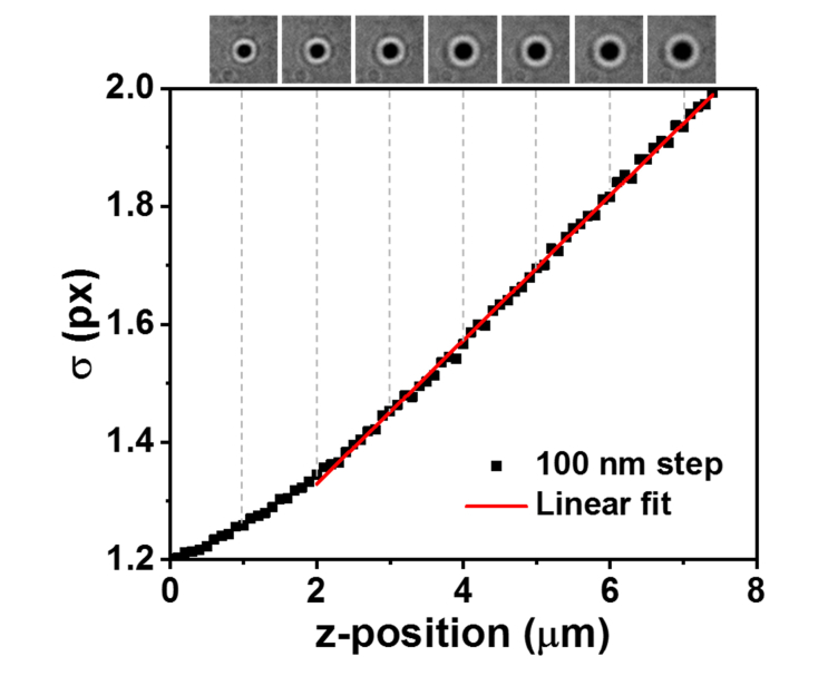
To obtain the precision of the drift correction, 1000 frames of image of the patterned coverslip were taken and the position of the marker was tracked over time in x, y and z directions (Fig. 2). A MATLAB based code, a-livePALM was used for tracking fiduciary markers [16]. The center of the x, y position of the marker is determined by Gaussian fitting and the axial position is determined by the standard deviation of the Gaussian function after calibration (Fig. 3). Figure 3 shows the linear dependence of the width of the marker on the axial position (slope = 0.114 ± 0.002 px/μm, average ± standard deviation, n = 5) and the relative axial position is estimated by using it. Since the size of the markers is consistent, the method for the estimation of the axial position is reliable. The range of the linear dependence of the width of the Gaussian function is 5 μm, which is reasonably large enough to correct axial drifts with linear fitting, although it is also possible to use a calibration curve. To calculate the drift correction precision, the deviations from the averaged trace were plotted as histograms. The drift correction precision obtained were 1.52 ± 0.05 nm for lateral dimension, and 6.15 ± 0.31 nm for axial dimension (average ± SEM, n = 5). As shown in Fig. 2, the movement of fiduciary markers are correlative in the same field of view. Since the movements are the same, one can obtain consistent drift correction precision regardless of whichever marker was chosen and the number of marker used for the drift correction. The lateral precision of the drift correction using T-NIL fiduciary marker is comparable to the previous report. Axial precision (from 17 nm to 6.2 nm) was improved from the previous report mainly due to the use of a more reliable algorithm to detect the markers. It is possible to apply the same method to correct the stage drift for longer period of time (>20 min) as shown in later experiments and in the previous publication [11]. The nanometer precision of the drift correction using this pattered fiduciary marker enables acquisition of images with resolution on par with the best resolution that super-resolution microscopy techniques can achieve.
Fig. 2.
The representative x, y and z positions from 4 fiduciary markers and the averages over the course of 1000 frames (top). The deviation from the average are plotted as histograms. The precision is defined as the standard deviation of the Gaussian fit (bottom).
Fig. 3.
z-axis calibration curve. The width (s) of the 2D Gaussian fit is linearly proportional to the z-position of the sample at 2 – 7 μm range. The bright field images of a marker show the progression of change in s as a function of the z-position.
3.3 Autofluorescence measurement
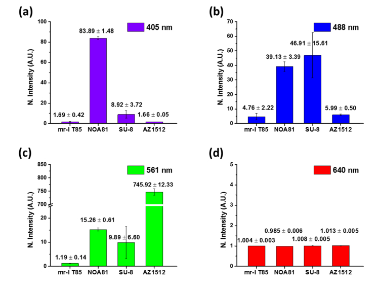
To evaluate the autofluorescence level of mr-I T85, we compared the background fluorescence intensities from mr-I T85, previously used UV curable polymer (NOA81), and two commonly used photoresists (SU-8 and AZ1512) at various excitation wavelengths (Fig. 4). Each material was spin coated on a coverslip surface to form 1 μm thickness layer. 1 mW (measured after the objective lens) of 405, 488, 561, and 640 nm lasers were illuminated on the samples respectively and the intensity levels were collected for each sample. The values were normalized by the autofluorescence level obtained from glass coverslips. Among the measured materials, mr-I T85 showed the lowest level of autofluorescence in all tested wavelengths.
Fig. 4.
Quantification of the auto-fluorescence of micro-pattern prepared using different resists under illumination with (a) 405 nm, (b) 488 nm, (c) 561 nm, or (d) 640 nm laser. The intensity of each illumination laser was fixed at 1 mW. The intensity value (y axis of the plots) is normalized with the value obtained from the glass (non-coated) surface. The shown error is standard deviation.
3.4 Bio-compatibility and stability of T-NIL fiduciary marker
To test the bio-compatibility of the mr-I T85 patterned coverslips, we cultured 3 types of cells with the patterned coverslips: HeLa cells with mScarlett-tubulin, glial cells with GFP-mitochondria, and primary culture rat hippocampal neurons with free-BFP (Fig. 5(a)). All tested cell types adhered, grew over patterned surface, and expressed transfected fluorescent proteins in a similar manner as cells cultured over glass or polymer treated glass surfaces (Fig. 5(a)). Therefore, the patterned surface is compatible with standard cell-lines and primary cultures and showed no cytotoxicity.
Fig. 5.
Bio-compatibility and adhesion to glass surface of T-NIL materials. (a) Bright field images of cultured cells and fluorescent protein expressions of the cells. (b, left) Under culture media, UV-curable resist (NOA81) locally detaches from the glass surface and forms large bubbles, indicated by the dotted white line (b, right), while T-NIL pattern (mr-I T85) remains stable for weeks.
In the previous UV-cured fiduciary marker, there was a problem of large water-trapped bubble formation between the fiduciary marker layer and the glass coverslip surface during cell culturing. This issue is more serious for cells that require long-term culturing, such as primary neurons. Figure 5(b) shows the surface of the fiduciary marker made of NOA81, UV-curable glue (left) and mr-I T85 (right). Trapped bubbles are indicated by the white arrows and the dotted white lines. The bubbles lift the patterned layer from the glass surface, causing a part of images to be out of focal plane and making it impossible to image the sample in the same field of view. On the contrary, the T-NIL fiduciary markers showed excellent stability in cell culturing conditions. Even after 2 weeks of long-term neuronal culture (Fig. 5(b), images taken at DIV 16), T-NIL fiduciary marker maintained the adhesion to the glass surface, having no stability or bubble trapping issues.
3.5 Live cell fluorescence image and SNR analysis
As the most direct application of coverslips coated with low autofluorescent T-NIL fiduciary markers, we obtained 4-color fluorescence images on HeLa cells (Fig. 6) and compared them to Glass coated coverslips. Cell were transiently transfected with two FPs, mScarlett-αtubulin (cytoskeleton marker protein, 561 nm excitation) and EGFP-ActA (mitochondria marker protein, 488 nm excitation). They were also stained with dyes for the nucleus (Hoecsht34580, 405 nm excitation) and for actin filament (SiR-actin, 640 nm excitation). The labeling of nuclei and the actin filaments were done before imaging. HeLa cells were incubated in DPBS with 1 μg/ml Hoecsht34580 for 5 min and 500 nM of SiR-actin for 15 min, respectively. After each step, the remaining fluorophores were washed by DPBS.
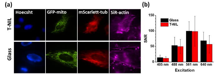
Fig. 6.
Live cell fluorescence images. (a) Fluorescent images of Hela cells on T-NIL fiduciary marker (left) and on glass surface (right). Cells were labeled by Hoecsht and SiR-actin, and expressed GFP-mitochondria and mScarlett-tubulin. (b) Measured Signal-to-Noise Ratio (SNR) of fluorescent beads on T-NIL and glass surface in 4 channels. The error bars indicate the standard deviation.
Fluorescently labeled cells were shown to give similarly low autofluorescence on the T-NIL as on the glass coverslips (Fig. 6(a)). The 4 channels used in cell imaging provided clear structures of nucleus, mitochondria, actin and microtubule filaments of the cells. We also analyzed the Signal-to-Noise Ratio (SNR) of 4 channels by imaging surface immobilized fluorescent beads (TetraSpeckTM Microspheres, 0.1 μm, fluorescent blue/green/orange/dark red, ThermoFisher) (Fig. 6(b)). The surface of the T-NIL and glass were coated with polyethyleneimine and the beads were immobilized on each surface. The SNR of each channel is calculated by the number of photons detected from a single bead divided by the background photons. In all cases, the SNR was comparable (at least 83%) for the T-NIL compared to glass. At the same time, the T-NIL provides the capability of the drift correction.
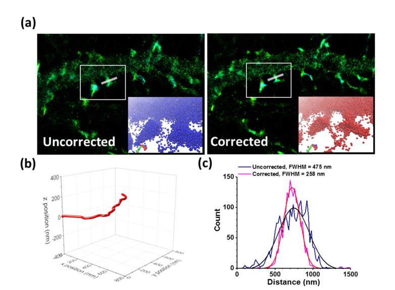
We applied this technique to demonstrate the drift correction for super-resolution image of fixed cells and live cells. The neurons cultured on T-NIL fiduciary marker were transfected with mEos3.2-actin plasmid and cultured for 24 hrs. mEos3.2 is a photoconvertible fluorescent protein (λmax-emission = 581 nm) that can be used for Photoactivated Localization Microscopy (PALM) [2]. The cells were fixed by 4% PFA for 15 min at room temperature and washed by PBS. The cells were imaged in PBS and mEos3.2 was photoconverted at 405 nm illumination (0.02 kW/cm2), followed by 561 nm excitation (0.5 kW/cm2). A total 16,000 frames of images were taken over 26 min with 10 Hz frame rate, and the image was reconstructed using quickPALM, an ImageJ plugin, and the 3D image was visualized by VMD in the insets (Fig. 7(a)). Without the drift correction, it is clear that the spine was blurred by the stage drift and the shapes of synaptic spines were distorted (Fig. 7(a)). The measured width of the shown spine is 475 nm. The drift occurred during the image acquisition is about 500 nm laterally (x and y), and 100 nm axially (z) (Fig. 7(b)). Upon correcting the stage drift based on 3D coordinates of the fiduciary markers, the line profile of the spine shows the width of 258 nm (Fig. 7(c)). In summary, the technique can correct the image distortion caused by the stage drift for the extended acquisition time of super-resolution microscopy and is able to correct the stage drift at least as large as hundreds of nanometers.
Fig. 7.
Super-resolution images of fixed neurons. Neurons. (a) PALM image of actin-mEos3.2 of fixed neurons before and after correction. The insets show the 3D visualization of the spines inside of the white rectangles (see Visualization 1 (12.4MB, avi) ). (b) The position of the fiduciary marker used for the image in 3D. The drift along z axis is relatively smaller (100 nm) than that of lateral dimension (~500 nm, x and y). (c) The linear profile of the selected area shows the width of the spine before and after the drift correction as FWHM of the Gaussian fit.
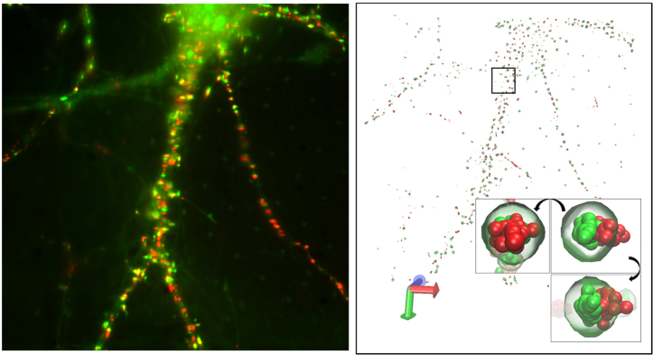
We also obtained super-resolution images of α-amino-3-hydroxy-5-methyl-4-isoxazolepropionic acid receptors (AMPARs) and Homer1c, a postsynaptic density marker protein, in live neurons (Fig. 8). The localization of the neuronal synaptic receptors, which ideally should be done with a few tens of nanometers, cannot be imaged precisely without the drift correction capability. Homer1c was labeled by fusing to mGeos, a photoactivatable green fluorescent protein. The AMPA-receptor GluR2 was biotinylated via standard methods [17] and was labeled with streptavidin-Atto647N. (Neurons were incubated in the imaging buffer, 10 mM HEPES, 1 mM MgCl2, 1.2 mM CaCl2, and 2 mM D-glucose and labeled with 300 pM streptavidin-Atto647N. After labeling, the cells were gently washed with the imaging buffer.) 1,000 frames of AMPAR (Atto647N) were taken under the illumination of 640 nm laser (0.3 kW/cm2), and subsequently, another 1,000 frames of PALM image of mGeos were taken under combination of 488 nm (0.3 kW/cm2) and 405 nm (0.02 kW/cm2) excitations with 20 Hz frame rate for imaging both AMPAR and Homer. Coordinates of AMPAR and Homer were localized by using ImageJ plugin quickPALM and the stage drift was corrected by using the method described above. Figure 8 shows the localized AMPAR and Homer in 3D. The conventional fluorescence image (Fig. 8, left) shows an overlay of Homer1c (green) and AMPAR (red). After localization analysis of the molecules, reconstructed 3D super-resolution image of AMPAR and Homer can reveal more details of the distributions of the protein clusters (Fig. 8, right). Detected AMPARs and Homer1c clusters are mostly co-localized in close proximity, as reported in the previous study [11]. Because the co-transfection efficiency of primary cells is often very low, it is absolutely crucial that every field of view has a set of fiduciary markers. While randomly placed beads may serve as fiduciary markers, it is not as robust as micropatterned fiduciary markers.
Fig. 8.
Super-resolution images of live neurons. Neurons. Overlay of the fluorescent image of Homer1c-mGeos (green) and streptavidin-Atto647N labeled AMPAR (red) of live neurons (left). 3-dimensional visualization of the super-resolution image of the neuron using VMD (right, see Visualization 2 (9.1MB, avi) ). Inset shows the visualization of a representative synapse of the neuron using VMD. The synapse is shown with rotation by 90° along two perpendicular axes.
4. Conclusion
In summary, we introduced a method based on a thermally-induced-pattern to create fiduciary markers on glass coverslips with low autofluorescence, high bio-compatibility, and capable of subtracting off greater than nanometer microscope stage drift. The drift correction precision we obtained was 1.6 and 1.3 nm laterally, and 6.1 nm axially under aqueous condition using a NA = 1.49 oil objective. The autofluorescent background level from the material is lower than that of UV-curable glue and photoresists, which are widely used for micro-patterning and fabrication in visible light spectra. We cultured a range of cells, including HeLa cells, glial cells and primary culture hippocampal neurons, and imaged them on fiduciary marker patterned coverslips with T-NIL. The cells proliferated and expressed transfected proteins. Also, there was no bubble trapped between the fiduciary marker layer and the glass surface, making microscopy over the entire region of interest. In the live-cell fluorescence images, the background coming from the pattern is as low as from bare glass coverslips in the 4 channels in visible light range. Furthermore, the low autofluorescence and capability of drift correction enables single-molecule localization microscopy with sub-diffraction-limited precision, enabling investigation of structure and dynamics of fixed and live cells. The T-NIL will provide the substrates that can be utilized for investigation in biological sciences that require high optical transmission and micropatterning.
Acknowledgments
The SEM analysis of this was carried out in the Frederick Seitz Materials Research Laboratory Central Research Facilities at the University of Illinois, and the fabrication was carried out in part in the Micro and Nanotechnology Laboratory and the Micro-Nano-Mechanical Systems Cleanroom at the University of Illinois. We also thank Glennys Mensing and Joseph Maduzia in the Micro-Nano-Mechanical Systems Cleanroom for the fruitful discussion on developing the fabrication process.
Funding
National Institutes of Health (NIH) (R01NS097610, R01NS100019); National Science Foundation (NSF) (PHY-1430124).
References and links
- 1.Yildiz A., Forkey J. N., McKinney S. A., Ha T., Goldman Y. E., Selvin P. R., “Myosin V Walks Hand-Over-Hand: Single Fluorophore Imaging with 1.5-nm Localization,” Science 300(5628), 2061–2065 (2003). 10.1126/science.1084398 [DOI] [PubMed] [Google Scholar]
- 2.Betzig E., Patterson G. H., Sougrat R., Lindwasser O. W., Olenych S., Bonifacino J. S., Davidson M. W., Lippincott-Schwartz J., Hess H. F., “Imaging Intracellular Fluorescent Proteins at Nanometer Resolution,” Science 313(5793), 1642–1645 (2006). 10.1126/science.1127344 [DOI] [PubMed] [Google Scholar]
- 3.Rust M. J., Bates M., Zhuang X., “Sub-diffraction-limit imaging by stochastic optical reconstruction microscopy (STORM),” Nat. Methods 3(10), 793–795 (2006). 10.1038/nmeth929 [DOI] [PMC free article] [PubMed] [Google Scholar]
- 4.Hess S. T., Girirajan T. P. K., Mason M. D., “Ultra-High Resolution Imaging by Fluorescence Photoactivation Localization Microscopy,” Biophys. J. 91(11), 4258–4272 (2006). 10.1529/biophysj.106.091116 [DOI] [PMC free article] [PubMed] [Google Scholar]
- 5.Heilemann M., van de Linde S., Schüttpelz M., Kasper R., Seefeldt B., Mukherjee A., Tinnefeld P., Sauer M., “Subdiffraction-Resolution Fluorescence Imaging with Conventional Fluorescent Probes,” Angew. Chem. Int. Ed. Engl. 47(33), 6172–6176 (2008). 10.1002/anie.200802376 [DOI] [PubMed] [Google Scholar]
- 6.Hell S. W., “Toward fluorescence nanoscopy,” Nat. Biotechnol. 21(11), 1347–1355 (2003). 10.1038/nbt895 [DOI] [PubMed] [Google Scholar]
- 7.Colomb W., Czerski J., Sau J. D., Sarkar S. K., “Estimation of microscope drift using fluorescent nanodiamonds as fiducial markers,” J. Microsc. 266(3), 298–306 (2017). 10.1111/jmi.12539 [DOI] [PubMed] [Google Scholar]
- 8.Wang Y., Schnitzbauer J., Hu Z., Li X., Cheng Y., Huang Z. L., Huang B., “Localization events-based sample drift correction for localization microscopy with redundant cross-correlation algorithm,” Opt. Express 22(13), 15982–15991 (2014). 10.1364/OE.22.015982 [DOI] [PMC free article] [PubMed] [Google Scholar]
- 9.Mlodzianoski M. J., Schreiner J. M., Callahan S. P., Smolková K., Dlasková A., Santorová J., Ježek P., Bewersdorf J., “Sample drift correction in 3D fluorescence photoactivation localization microscopy,” Opt. Express 19(16), 15009–15019 (2011). 10.1364/OE.19.015009 [DOI] [PubMed] [Google Scholar]
- 10.Lee S. H., Baday M., Tjioe M., Simonson P. D., Zhang R., Cai E., Selvin P. R., “Using fixed fiduciary markers for stage drift correction,” Opt. Express 20(11), 12177–12183 (2012). 10.1364/OE.20.012177 [DOI] [PMC free article] [PubMed] [Google Scholar]
- 11.Lee S. H., Jin C., Cai E., Ge P., Ishitsuka Y., Teng K. W., de Thomaz A. A., Nall D., Baday M., Jeyifous O., Demonte D., Dundas C. M., Park S., Delgado J. Y., Green W. N., Selvin P. R., “Super-resolution imaging of synaptic and extra-synaptic AMPA receptors with different-sized fluorescent probes,” eLife 6, e27744 (2017). [DOI] [PMC free article] [PubMed] [Google Scholar]
- 12.Teng K. W., Ishitsuka Y., Ren P., Youn Y., Deng X., Ge P., Belmont A. S., Selvin P. R., Selvin P. R., “Labeling proteins inside living cells using external fluorophores for microscopy,” eLife 5, e20378 (2016). 10.7554/eLife.20378 [DOI] [PMC free article] [PubMed] [Google Scholar]
- 13.Pai J. H., Wang Y., Salazar G. T., Sims C. E., Bachman M., Li G. P., Allbritton N. L., “Photoresist with low fluorescence for bioanalytical applications,” Anal. Chem. 79(22), 8774–8780 (2007). 10.1021/ac071528q [DOI] [PMC free article] [PubMed] [Google Scholar]
- 14.Tamai H., Maruo K., Ueno H., Terao K., Kotera H., Suzuki T., “Development of low-fluorescence thick photoresist for high-aspect-ratio microstructure in bio-application,” Biomicrofluidics 9(2), 022405 (2015). 10.1063/1.4917511 [DOI] [PMC free article] [PubMed] [Google Scholar]
- 15.Huang B., Wang W., Bates M., Zhuang X., “Three-dimensional super-resolution imaging by stochastic optical reconstruction microscopy,” Science 319(5864), 810–813 (2008). 10.1126/science.1153529 [DOI] [PMC free article] [PubMed] [Google Scholar]
- 16.Li Y., Ishitsuka Y., Hedde P. N., Nienhaus G. U., “Fast and efficient molecule detection in localization-based super-resolution microscopy by parallel adaptive histogram equalization,” ACS Nano 7(6), 5207–5214 (2013). 10.1021/nn4009388 [DOI] [PubMed] [Google Scholar]
- 17.Howarth M., Takao K., Hayashi Y., Ting A. Y., “Targeting quantum dots to surface proteins in living cells with biotin ligase,” Proc. Natl. Acad. Sci. U.S.A. 102(21), 7583–7588 (2005). 10.1073/pnas.0503125102 [DOI] [PMC free article] [PubMed] [Google Scholar]


