Abstract
Maximizing the power of multi-element phased arrays is a critical factor for high intensity focused ultrasound (HIFU) applications such as histotripsy and transcostal sonications. This can be achieved by a tight packing of the array elements. Good electronic focusing capabilities are also required. Currently used quasi-random arrays with a relatively low filling factor of about 60% have this focusing ability. Here, a novel method of designing random HIFU arrays with the maximum possible filling factor (100% if no gaps between elements needed in practice are introduced) and polygonal elements of equal area and slightly different shape based on the capacity-constrained tessellation is described. The method is validated by comparing designs of two arrays with the same geometric and physical parameters: an existing 256-element array with a compact 16-spirals layout of circular elements and the proposed array with the maximum possible filling factor. Introduction of a 0.5 mm gap between the elements of the new array resulted in a reduction of its filling factor to 86% as compared with 61% for the spiral array. It is shown that for the same intensity at the elements, the proposed array provides two times higher total power while maintaining the same electronic focusing capabilities as compared to the spiral one. Furthermore, the surface of the capacity-constrained tessellation array, its boundary, and a central opening can have arbitrary shapes.
Index Terms: Focusing, high intensity focused ultrasound (HIFU), high power quasi-random phased array, nonlinear waves, shock front, tight packing, filling factor
I. Introduction
HIGH intensity focused ultrasound (HIFU) is an emerging medical technology in which an ultrasound beam is focused within deep structures of the body to locally affect the targeted site without damaging surrounding tissues and organs [1]. HIFU sonications are often performed using multi-element phased arrays comprising a large number of relatively small-sized elements (Fig. 1). Independent variation of the amplitudes and phases at the array elements allows electronic steering of the focus, compensation of aberrations that occur when the HIFU beam passes through inhomogeneous tissue structures, and creation of different combinations of several foci [2], [3].
Fig. 1.
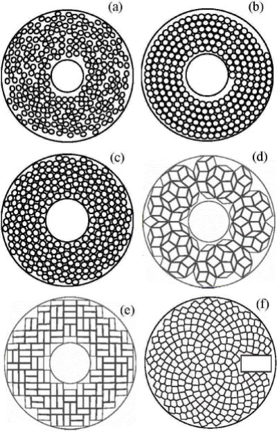
Sketches of different densely populated arrays having quasi-random (a), Archimedean spiral (b), and compact 16-spiral layout (c) distributions of circular elements; Penrose rhombus (d) and rectangular (e) tiling arrays; an array with Fermat’s spiral distribution of Voronoi tessellation-shaped elements (VTFS-array) (f).
To suppress the formation of grating lobes associated with densely populated phased arrays, the distance between the centers of the array elements must be less than λ/2, where λ is the ultrasound wavelength [4]. Such a requirement leads to a very high number of elements and electronic channels to produce an array with a sufficiently large aperture and acoustic power needed for surgical applications. Current HIFU arrays consist of a moderate (256 to 1024) number of elements with individual element sizes exceeding several wavelengths [5]–[7], and formation of grating lobes is mitigated by arranging the array elements in various non-periodic patterns (Fig. 1) [8]–[11].
In addition to non-periodic spatial structure, HIFU technologies for clinical applications such as cavitation and boiling histotripsy [12]-[14], transcostal treatments through skull or rib cage [5], [15], [16], and deep abdominal treatments [13], [14], [17] require very high peak output power of the array. In these cases, the intensity at the array elements may exceed maximum permissible values of 30 – 40 W/cm2 [15], [18], [19]. One approach to increasing the acoustic power of an array of given dimensions is to enlarge its active radiating surface, i.e., maximize its filling factor. For example, recent numerical studies showed that boiling histotripsy treatments are feasible while focusing on brain through the intact skull using arrays with a filling factor of more than 80% [16]. The feasibility of transcranial cavitation histotripsy has been demonstrated in experimental settings with human skull [21]. Thus, designing phased arrays with simultaneous tight packing of the elements and their non-periodic distribution over the array surface is an important factor for advancing the HIFU technology.
Packing efficiency of existing quasi-random arrays (Fig. 1(a)) is relatively low, with the filling factor of about 40–60%, which limits the maximum array power [2], [6], [21]. Several groups have developed various models of non-periodic tightly packed arrays. Designs with spiral layout and different geometry of the elements have been proposed. The use of array configurations with circular elements distributed in a single Archimedean spiral (Fig. 1(b)) or 16-arm spiral (Fig. 1(c)) resulted in increase of the filling factor up to Ψ = 61% with 0.5 mm gaps between the elements [8], [19], [22]. Here the filling factor is
| (1) |
where Sactive is the total area of all elements of the array, S is the area of the array shell. Furthermore, the use of trapezoidal elements in a 16-arm spiral configuration Fig. 1(c) can additionally increase the filling factor [8]. Two array configurations based on the Penrose rhombus tiling (70% filling factor with 0.5 mm gaps between the elements) and on a non-periodically arranged rectangular elements (71% filling fraction with 0.5 mm gaps between the elements) were also proposed (Fig. 1(d), and (e)) [9].
Recently, Ramaekers et al. suggested an array model with a filling factor of about Ψ = 74% with 0.5 mm gaps between the elements (Fig. 1(f)) using acoustic elements shaped as Voronoi tessellation cells (VTFS-array) and positioned following the pattern of Fermat’s spiral [10], [11]. The transducer has been designed and manufactured comprising 256 elements and a small opening that allowed the placement of an ultrasound imaging probe (Fig. 1(f)) [10], [11]. Despite the significant increase in the filling factor of this type of array, they still did not achieve the maximum possible filling factor because of the gaps on the periphery of the transducer and around openings for holding an imaging probe. Furthermore, the densest VTFS-array was designed by applying Voronoi tessellation to partition the area of the array into polygonal cells which does not ensure the areas of the cells to be equal. Differing areas of individual elements can create certain complications in the electrical matching of outputs of power amplifiers with different elements and may affect the array steering capabilities.
Here we propose a novel method of designing patterns of fully populated random HIFU arrays with maximum possible filling of their surface with equal area polygonal elements (Ψ = 100% if no gaps between elements needed in practice are introduced). This method is based on partitioning the spherical surface of the array by applying capacity-constrained tessellation, which was previously introduced for the problems of computer graphics [23]. The tessellation method has been improved here by introducing a mechanism for non-periodic distribution of the tessellation cells. Fully populated random arrays proposed in this study can have arbitrary shaped surface, boundary, and opening for an imaging probe.
In this work, an example of such a fully populated array design is considered and tested by comparing its electronic focusing capabilities with an existing 256-element array with a compact 16-spirals layout of circular elements (Fig. 1(c)) [19]. The two arrays had the same frequency, geometry of the spherical shell with a central opening, area of the elements, and minimum gaps between their elements.
II. Methods
A. Tiling the array surface with equal-area polygons
As an example, consider the following step-by-step implementation of the capacity constrained tessellation to obtain a five-element array shaped as a spherical cap with a circular central opening.
-
1
First, a large number of sampling points with uniformly distributed coordinates over the array surface (S) is generated (Fig. 2(a)) [24]. In the other words, the probability P that a random point belongs to a surface element dS is P = dS/S and does not depend on the position of the element dS on the sphere.
-
2
Second, all the points are divided into N randomly mixed sets of points (point clouds) (Fig. 2(a)) containing an equal number of M points. In this example N = 5, M = 128, and the total number of points is N·M = 640. The points of five different clouds are depicted by different types of markers in Fig. 2(a) (plus sign, circle, cross, point, and diamond). Due to the fact that the division of the points into classes occurs randomly, the clouds of different classes are strongly mixed.
-
3
The next step of the algorithm can be represented as a “separation” of N portions of various immiscible liquids mixed in a “container” shaped as a spherical shell. Each portion contains M particles. It is clear that the final state after the separation of such “liquids” (Fig. 2(b)) will correspond to the partition of the volume of the “container” into tessellation cells. This step of the algorithm on which the iterative process of pairwise separation of the point clouds is implemented has been analyzed in detail in [23]; here we present its technical implementation.
Fig. 2.
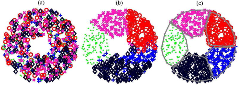
Illustration of the capacity-constrained tessellation as an iterative point-clouds dispersal process for designing the example of a 5-element array. Here five different point clouds are denoted as markers (plus sign, circle, cross, point, and diamond). (a) is a completely blended state (iteration 0); (b) is the beginning (iteration 2), and (c) is the completion (iteration 5) of dispersal process.
At each iteration, all possible pairs of point clouds are considered sequentially. For example, consider the clouds depicted with “+” and “o” markers (Fig. 2(a)). Denote the radius vectors of the points of the first cloud as ai, (i = 1…M) and the center of mass of the cloud (a1 + a2… aM)/M projected normally on the spherical surface of the array as A. Similarly, for the second point cloud, denote bj (j = 1…M) and B. Then, all possible pairs (ai, bj) are considered. If the point ai of the first cloud is located inside the second cloud, and the point bj of the second cloud is located inside the first one, then an exchange of points occurs so, that bj is assigned to the first cloud, and ai to the second one.
In [23], a function that identifies the pairs of points to be exchanged was introduced:
| (2) |
Here, ρ(X, Y) is the distance between two points in the spherical metric, or, in the other words, the length of the shortest arc of the great circle passing through the points X and Y.
If χ(ai, bj) > 0, then the points ai and bj are exchanged, as described above, otherwise there is no exchange. After the first iteration, the clouds appear already much less mixed (Fig. 2(b)). However, intersections of different clouds are still observed. Therefore, the iterations are continued until the condition χ(ai, bj)≤ 0 is satisfied for all pairs of points and all pairs of clouds. The fulfillment of this condition indicates the complete separation of clouds (Fig. 2(ñ)). Note that after the separation, each of the N = 5 clouds contains the same number of M = 128 points, since the exchange of points between clouds has always been pairwise. Multiple test calculations performed for various cases of array designs showed robust convergence of such iteration procedure.
-
4
To draw the boundary for all elements of the array, a convex rim surrounding the outer points of each element is constructed (Fig. 2(ñ), thick curves). In the case of a large number of sampling points set at the first step of the algorithm, the resulting polygons on the spherical cup of the array are precisely the tessellation cells that fill the array surface without any gaps. Note that according to the algorithm, all the array elements contain the same number of M uniformly distributed sampling points. Therefore, since the number of uniformly distributed points within each element is proportional to a consistent unbiased estimation of its area, the areas of all elements are equal in the limit of a large number of points M.
-
5
Finally, a gap h which is necessary to avoid electrical breakdown between the neighboring elements is introduced by translating the boundary of each element by a distance of h/2 toward its center.
An analytical estimate of the maximum possible filling factor of a fully populated array can be obtained assuming that this gap is much smaller than the size of the element, and that the length of each element rim L is approximated by a perimeter of a circle of the same area . Then the half gap area surrounding the element is . The approximate filling factor of the array ψ = Sel/(Sel + ΔSel) ≈ 1 − ΔSel/Sel then can be calculated as follows:
| (3) |
B. Design of a random phased array with the maximum possible filling factor
Following the proposed capacity-constrained tessellation procedure, a 364-element random array with 100% filling factor (if no gaps between elements needed in practice are introduced) was designed. The geometrical parameters of this array were chosen so that its output could be compared with the existing multi-element 16-arm spiral HIFU array recently designed for boiling histotripsy applications at the Applied Physics Laboratory, University of Washington in Seattle and manufactured by Imasonic (Voray Sur L’ognon, France) [19]. The existing spiral array operates at a frequency of 1.5 MHz and comprises 256 circular elements of 7 mm diameter (Sel = 38.5 mm2 area) arranged in a compact spiral layout (Fig. 1(c)). The spherically curved surface of the array has an aperture of 144 mm and a focal length of 120 mm. In addition, there is a central opening of 50 mm diameter to fit an ultrasound imaging probe. The total area of the array surface is S = 161 cm2. To avoid electrical breakdown between neighboring elements, there are h = 0.5 mm gaps between the elements located on each spiral of the array resulting in a filling factor of Ψ = 61% (Eq. 1).
The proposed array was assumed to have the same operating frequency, aperture, focal length, element area, gaps between the elements, and size of the central opening. The number of elements N = 364 was obtained by dividing the total area of the array surface by the area of the array element Sel with half of the adjacent gap . With a gap of h = 0.5 mm between the elements, the filling factor of the fully populated array decreases from 100% to 86%, which is in good agreement with the approximate analytical estimate of the maximum possible filling factor of an array (3). Calculations show that with the same area of the elements, 38.5 mm2, the filling factor is increased to 91.5% or 94% when the gap between the elements is reduced to 0.3 or 0.2 mm, respectively.
The following values of tessellation parameters were used in simulations: N = 364, M = 10240 (total number of points N·M = 3727360). Such a large number of points provides a very small variation in the areas of the elements: , where is the dispersion of the element area, is the mean area of the element. If a smaller variation is desired, the number of discretization points can be increased. Note that in the construction of a tessellation there is a separation of strongly mixed point-clouds consisting of a large number of points, and the resulting tessellation cells (array elements) are located non-periodically (Fig. 4(b)).
Fig. 4.
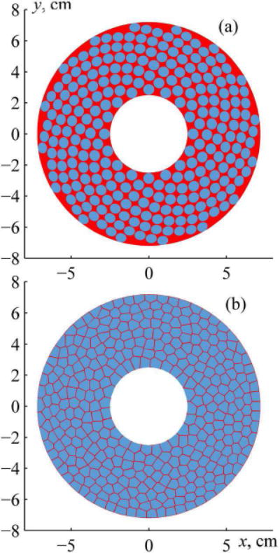
(a) A front view sketch of the existing 256-element array with a compact 16-spirals layout of circular elements. (b) 364-element capacity-constrained tessellation array with elements shaped as spherical polygons. The two arrays have the same parameters: 1.5 MHz frequency, 144 mm aperture, 120 mm focal length, 38.5 mm2 area of each element, 0.5 mm gap between the elements, and 50 mm central opening for imaging probe.
C. An analytical method for calculating the field of the array with polygon-shaped elements
To evaluate the field quality of multi-element phased arrays for different locations of the electronically steered array focus, it is necessary to perform multiple calculations of their fields. The conventional approach is based on numerical calculation of the Rayleigh integral for the complex amplitude of acoustic pressure [25], [26]:
| (4) |
with time dependence described as exp(−iωt). Here i is the imaginary unit, ω = 2πf is the angular frequency of the array, k = ω/c0 is the wavenumber, c0 is the sound speed, ρ0 is the density of the medium, S is the surface area of the array, υn is the complex amplitude of the normal component of the vibration velocity at the surface of the array, and R is the distance from the surface element dS′ to the observation point;.
Direct calculation of the Rayleigh integral (4) is a time-consuming process when performing multiple simulations for different locations of the focus. Recently, a fast analytical approach was developed to accelerate the computations for the region close to the geometrical focus, which is of most interest for therapeutic treatments [27]. The distance from each of the array elements to the focus is much larger than the extent of its near field. Therefore it was proposed to calculate the field of the array with the circular elements as a sum of analytical solutions for the far field of each element. Adopting this analytical method results in a much faster calculation of the field of a multi-element array than direct numerical integration whilst preserving the same accuracy of the results [27]. Based on this approach, an open source software package “T-Array”, developed at Moscow State University (www.limu.msu.ru) and freely available to analyze fields of arrays of circular elements was used here to analyze the field of the spiral array.
For the new array design, this method was modified for calculating the pressure amplitude in the far field of the elements shaped as convex polygons (Fig. 3). Following the same idea, each polygonal element of the array was divided into a set of right-angle triangles (Fig. 3(a)). The solution for the complex amplitude of acoustic pressure in the far field of the piston element shaped as a right-angle triangle (Fig. 3(b)) can be obtained analytically:
| (5) |
Here a and b are the legs of the right triangle, p0 = ρ0c0υn is the characteristic pressure at the surface of the element, , and (x, y, z) are the coordinates of the observation point (Fig. 3(b)). For a typical triangular element, the result, obtained within the far field approximation, is highly consistent with the data obtained using direct numerical calculation the Rayleigh integral already at distances larger than 2 cm from the array surface (Fig. 3(c)).
Fig. 3.
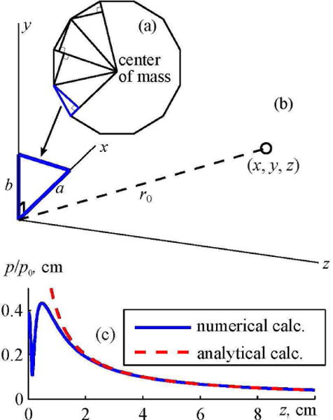
Diagram illustrating an analytical method for calculating the far field of a polygonal array element. (a) Partitioning of a polygonal element into a set of right angled triangles. (b) Analytical calculation of the field of a right angled triangle at a point with coordinates (x,y,z). (c) Comparison of pressure amplitude distributions along the axis z of the element in the form of a right angled triangle. Solid curve shows the results of a numerical calculation using the Rayleigh integral; dashed curve shows the results of an analytical solutions obtained in the far-field approximation. The element has dimensions of a = 4 mm, b = 3 mm and the frequency of 1 MHz.
III. Results
The patterns of the existing spiral compact HIFU array and the proposed random array fully populated with polygon-shaped elements of equal area are compared in Fig. 4. Projection of the spherical array shell and the elements on the initial plane z = 0 is shown. These two arrays are compared below in terms of the focal pressure levels, field quality, and electronic focus steering capabilities.
First, consider focusing of the arrays at their center of curvature. Figs. 5(a, e) depict the pressure amplitude distribution pF/p0 normalized to the pressure amplitude p0 at the array element in the plane region yz passing through the array axis z and vertical axis y (“axial plane”) for the existing spiral array and the new array. Fig. 5(b, f) shows the same distribution in another plane region xy perpendicular to the axis and passing through the center of curvature of the array (“focal plane”). It is seen that for the same source pressure amplitude p0, focal pressure amplitude is higher for fully populated array as compared with the existing spiral array . Thus, the proposed array provides two times higher focal intensity compared with the existing one: . This result is expected as the focal intensity depends on the active area of the array (or its filling factor) as IF ∼ Ψ2. Hence, the ratio of the intensities of two arrays is . The proposed array therefore would require only half of the intensity at the surface of the elements than the spiral one to generate the same focal intensity.
Fig. 5.
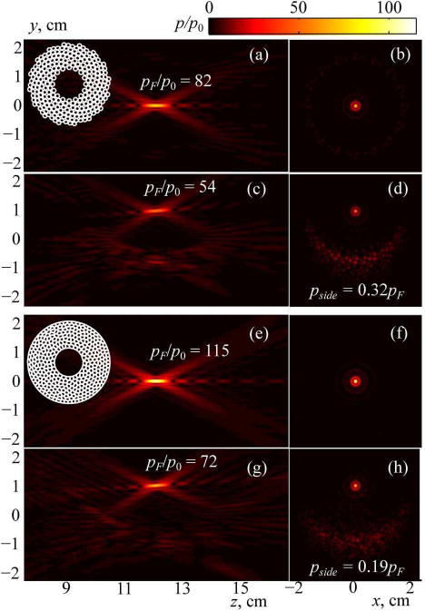
Simulated 2D distributions of the pressure amplitude in the axial (on the left) and focal (on the right) planes of the 256-element array with compact 16-spirals layout of circular elements (a–d) and capacity-constrained tessellation array with elements shaped as spherical polygons (e–h). Results are normalized to the pressure amplitude at the array elements p0. The focus of the arrays is positioned either at their geometric center (a, b and e, f) or electronically shifted vertically by 1 cm off the axis (c, d and g, h). The values of the pressure amplitude at the focus pF/p0 and the maximum amplitude of the grating lobes pside are shown for each steering position of the focus.
To validate the random nature of the fully populated array it is also necessary to evaluate its dynamic focusing capabilities. Fig. 5(c, g) shows normalized pressure amplitude distributions pF/p0 for two arrays in the axial plane and Fig. 5(d, h) shows them in the focal plane when the focus is shifted off the axis by 10 mm. Two side effects related to the discrete structure of the arrays are observed. The pressure amplitude decreases by approximately 40% compared to the case without steering (a decrease in “efficiency”); at the same time, a region of discrete scattered grating lobes is formed in the field pattern (a decrease in “safety”). Note, that in the case of the transverse focus shift, the proposed fully populated array generates a field of even higher quality (Fig. 5(g, h)) in comparison with the spiral array (Fig. 5(c, d)): the pressure levels of the grating lobes in the field of fully populated array are lower and almost invisible in the field pattern.
To estimate the dynamic focusing capabilities of the two arrays in more detail, analysis of the appearance of side effects was performed by calculating the array field for multiple steering positions of the focus and evaluating the manifestation of two side effects: decreasing “efficiency” and “safety” of sonications. According to the criteria considered in earlier studies [8], [27], focus steering is efficient when the intensity at the shifted focus is higher than 50% of the maximum achievable value and the steering is safe if the intensity of the grating lobes is less than 10% of the focal intensity.
Figure 6(a) shows contours surrounding the regions of the safe (thick gray lines) and efficient (thin black lines) focus steering in the axial plane yz. The dashed contours represent data for the existing spiral array, while the solid contours show data for the proposed fully populated array. In Fig. 6(b) the same contour regions are shown in the focal plane xy. It is seen that the region of safe focusing for the fully populated array (thick solid line) is larger in the transverse direction and smaller in the axial direction as compared to that of the spiral array (thick dashed line). The regions of efficient focusing of the two arrays are very close; that for the proposed array (thin solid line) is slightly smaller than the region for the existing array (thin dashed line). However, the maximum difference of allowable focus steering in the axial direction is less than 1 mm, which is only 3% of the axial size of the region of allowable focusing, 3.5 cm, and thus not significant for practical use. Finally, since for each of the arrays the region of both safe and efficient (i.e., “allowable”) focus steering coincides with the region of efficient focusing, then the areas of allowable dynamic focusing are the same for the two arrays.
Fig. 6.
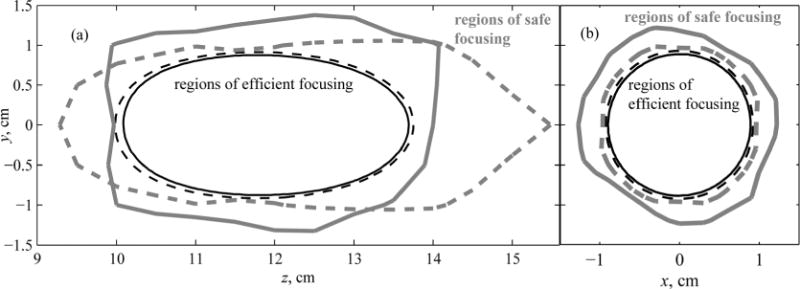
Contours of regions of focus steering for the existing spiral array (dashed curves) and capacity-constrained array (solid curves). Within the thin lined contours, the intensity in the main maximum decreases by less than 50% of the largest achievable value (marked “regions of efficient focusing”). Within the thick lined contours, the intensity of the largest grating lobe does not exceed 10% of the intensity in the main maximum (marked “regions of safe focusing”). The results are given (a) in the axial and (b) in the focal planes of the arrays.
IV. Discussion and Conclusions
In this study, a novel class of fully populated multi-element HIFU arrays is proposed. The arrays consist of radiating elements shaped as spherical polygons of equal area, obtained using the method of capacity-constrained tessellation. The method provides the maximum possible filling of the array surface with the elements (100% if no gaps between elements needed in practice are introduced), while ensuring their non-periodical arrangement.
To test the proposed method two arrays with the same geometric and physical parameters were compared in terms of the focal intensity and focus steering capabilities: the dense spiral array that has been recently designed and manufactured for boiling histotripsy applications and the fully populated array with the maximum possible filling factor. Calculations showed that for a given initial intensity at the array elements, the proposed array provides two times higher power output and thus focal intensity as compared with the existing compact spiral array while maintaining the same dynamic focusing capabilities. Therefore, for the same size of elements and operating frequency the model of the fully populated array provides a means of partitioning the array surface into elements of equal size without compromising the focus steering capabilities compared with existing non-periodic arrays.
An additional advantage of the proposed method is the possibility to design an array of arbitrary shape for different HIFU applications. This capability is illustrated in Fig. 7 for a model of a rectangular array with the circular opening (a), and a model of circular array with a square opening (b). The method can be directly implemented for plane and spherical surfaces with circular or square boundary shape. Additional studies are required to extend it to other specified geometries of the array surface or more complex boundaries.
Fig. 7.
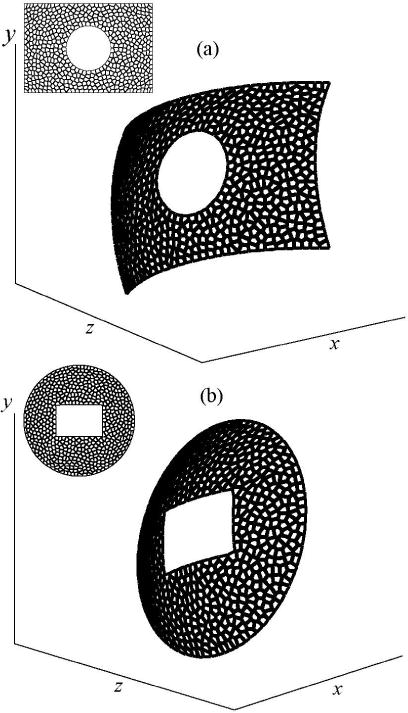
Examples of the fully populated array designs: (a) a rectangular array with a circular opening; (b) a circular array with a square opening.
In conclusion, it is important to note that fully populated arrays can be a critical factor in developing HIFU systems to implement recently developed treatments such as boiling histotripsy while focusing on brain through the intact skull. As shown theoretically in previous studies, such operations can be performed using arrays with high values of the filling factor [16], [28].
Acknowledgments
The authors are grateful to Prof. Jeffrey Hand, King’s College London for fruitful discussions and editorial comments.
The work was supported in part by Russian Science Foundation (14-12-00974), PhD student stipend from the “Basis” Foundation for the Development of Theoretical Physics, and the National Institutes of Health (EB007643).
Biographies
Pavel B. Rosnitskiy received the M.S. degree in physics from Moscow State University (MSU), Moscow, Russia, in 2016, where he is currently pursuing the Ph.D. degree with the Department of Acoustics, Physics Faculty. His current research interests include nonlinear acoustics and therapeutic applications of high intensity focused ultrasound waves with shocks. Mr. Rosnitskiy was awarded by scholarships named after R. V. Khokhlov and S. I. Vavilov, a Scholarship of the President of Russia (2014 – 2016), and by International Student stipend from the Acoustical Society of America (2016). He was also recognized for the best undergraduate student project (2013), the best M.S. thesis (2016), and as the best student of the Physics Faculty at MSU (2015).
Boris A. Vysokanov received the M.S. degree in mathematics from Moscow State University (MSU), Moscow, Russia, in 2015, and is currently pursuing the Ph.D. Degree at the Department of Higher Algebra, Faculty of Mechanics and Mathematics. Mr. Vysokanov also received an education in computer science at Yandex School of Data Analysis in 2014. His current research interests include computer science, combinatorial group theory and applications of topological methods to solve equations over groups.
Leonid R. Gavrilov graduated from the St. Petersburg Electrotechnical Institute in 1961. He received the Ph.D. degree in engineering from the Central Institute of Turbo-Machines, Sankt-Petersburg, in 1966 and D.Sc. degree from the N. N. Andreyev Acoustics Institute, Moscow, in 1982. Since 1967, he has been with the N. N. Andreyev Acoustics Institute studying the acoustical properties of gas bubbles in liquids and, since 1969, the application of focused ultrasound in medicine and physiology being a Head of the Laboratory of Medical Acoustics (1979 – 1998) and currently working as a Principal Research Scientist. He was an Honorary Senior Research Fellow in the Queen’s University of Belfast (1993 – 1994) and a Senior Research Officer in the Radiological Sciences Unit, Hammersmith Hospital, Imperial College, London (1995 – 1998), UK. He is Co-Chair of the Section on Medical Acoustics of the Russian Acoustical Society. His current research interests are in the application of focused ultrasound for stimulation of neural structures, therapeutic ultrasound applications, developing high-intensity phased arrays, biological effects and safety aspects of therapeutic ultrasound. He was awarded by the Certificate “History of Medical Ultrasound. Pioneer Award” in 1988 from the World Federation of Ultrasound in Medicine and Biology, AIUM.
Oleg A. Sapozhnikov received the M.S. degree in physics, and the Ph.D. and D.Sc. degrees in acoustics from Moscow State University (MSU), Moscow, Russia, in 1985, 1988, and 2008, respectively. After graduation, he was with MSU, where he is currently a Professor with the Department of Acoustics of the Physics Faculty. Since 1996, he has been with the Center for Industrial and Medical Ultrasound in the Applied Physics Laboratory at the University of Washington, Seattle, WA, USA. His current research interests include physical acoustics, nonlinear wave phenomena, medical ultrasound including shock wave lithotripsy, high intensity focused ultrasound, and ultrasound-based imaging. Dr. Sapozhnikov has been a member of the International Society for Therapeutic Ultrasound, since 2008; a member of the Board of International Congress on Ultrasonics, since 2009; the Head of the Physical Ultrasound Division of the Scientific Council on Acoustics of the Russian Academy of Sciences, since 2009; and a Fellow (since 2009). He was a recipient of the M.V. Lomonosov Prize in Physics in 1991, a Prize of the European Academy for Young Russian Scientists in 1994, and an Early Career Award of the International Commission for Acoustics in 2004.

Vera A. Khokhlova received the M.S. degree in physics, and the Ph.D. and D.Sc. degrees in acoustics from Moscow State University (MSU), Moscow, Russia, in 1986, 1991, and 2012, respectively. After graduation from the Ph.D. program, she was appointed by MSU where she is currently an Associate Professor with the Department of Acoustics of the Physics Faculty. Since 1995, she has been with the Center for Industrial and Medical Ultrasound of the Applied Physics Laboratory, University of Washington, Seattle, WA, USA. Her current research interests include nonlinear acoustics, therapeutic ultrasound including metrology and bioeffects of high intensity focused ultrasound fields, shock wave focusing, nonlinear wave propagation in inhomogeneous media, and nonlinear modeling. Dr. Khokhlova is a Fellow, since 2008, and was a member of the Executive Council of the Acoustical Society of America from 2012 to 2015 and a member of the Board of the International Society for Therapeutic Ultrasound (2004 – 2008 and 2011 – 2014). She has been a member of the Physical Ultrasound Division of the Scientific Council on Acoustics of the Russian Academy of Sciences since 2009 and an Associate Editor of the IEEE UFFC since 2013.
Contributor Information
Pavel B. Rosnitskiy, Physics Faculty, M. V. Lomonosov Moscow State University, Moscow, Russia
Boris A. Vysokanov, Faculty of Mechanics and Mathematics, M. V. Lomonosov Moscow State University, Moscow, Russia
Leonid R. Gavrilov, N.N. Andreyev Acoustics Institute, Moscow, Russia
Oleg A. Sapozhnikov, Physics Faculty, M. V. Lomonosov Moscow State University, Moscow, Russia Center for Industrial and Medical Ultrasound, Applied Physics Laboratory, University of Washington, Seattle, WA.
Vera A. Khokhlova, Physics Faculty, M. V. Lomonosov Moscow State University, Moscow, Russia Center for Industrial and Medical Ultrasound, Applied Physics Laboratory, University of Washington, Seattle, WA.
References
- 1.Ellens NPK, Hynenen K. High-intensity focused ultrasound for medical therapy. In: Gallego-Juarez JA, Graff KF, editors. Power Ultrasonics Applications of High-intensity Ultrasound. Vol. 166. Elsevier; Cambridge: 2015. pp. 661–693. (Woodhead Publishing Series in Electronic and Optical Materials). Chapter II. [Google Scholar]
- 2.Gavrilov LR, Hand JW. A theoretical assessment of the relative performance of spherical phased arrays for ultrasound surgery and therapy. IEEE Trans Ultrason, Ferroelect, Freq Control. 2000;47(1):125–139. doi: 10.1109/58.818755. [DOI] [PubMed] [Google Scholar]
- 3.Hynynen K, Jones RM. Image-guided ultrasound phased arrays are a disruptive technology for non-invasive therapy. Phys Med Biol. 2016;61(17):R206–R248. doi: 10.1088/0031-9155/61/17/R206. [DOI] [PMC free article] [PubMed] [Google Scholar]
- 4.Skolnik MI. Introduction to Radar Systems. New York, NY: McGraw-Hill; 1962. [Google Scholar]
- 5.Pernot M, Aubry J-F, Tanter M, Thomas J-L, Fink M. High power transcranial beam steering for ultrasonic brain therapy. Phys Med Biol. 2003;48(16):2577–2589. doi: 10.1109/TMI.2010.2076829. [DOI] [PMC free article] [PubMed] [Google Scholar]
- 6.Hand JW, Shaw A, Sadhoo N, Rajagopal S, Dickinson RJ, Gavrilov LR. A random phased array device for delivery of high intensity focused ultrasound. Phys Med Biol. 2009;54:5675–5693. doi: 10.1088/0031-9155/54/19/002. [DOI] [PubMed] [Google Scholar]
- 7.Clement GT, Sun J, Giesecke T, Hynynen K. A hemisphere array for non invasive ultrasound surgery and therapy. Phys Med Biol. 2000;45:3707–3719. doi: 10.1088/0031-9155/45/12/314. [DOI] [PubMed] [Google Scholar]
- 8.Gavrilov LR, Sapozhnikov OA, Khokhlova VA. Spiral arrangement of elements of two-dimensional ultrasonic therapeutic arrays as a way of increasing the intensity at the focus. Bulletin of the Russian Academy of Sciences Physics. 2015;79(10):1232–1237. [Google Scholar]
- 9.Raju BI, Hall CS, Seip R. Ultrasound therapy transducers with space-filling non-periodic arrays. IEEE Trans Ultrason, Ferroelect, Freq Control. 2011;58(5):944–954. doi: 10.1109/TUFFC.2011.1895. [DOI] [PubMed] [Google Scholar]
- 10.Ramaekers P, Ries M, Moonen CTW, de Greef M. Improved intercostal HIFU ablation using a phased array transducer based on Fermat’s spiral and Voronoi tessellation: A numerical evaluation. Med Phys. 2017;44(3):1071–1088. doi: 10.1002/mp.12082. [DOI] [PubMed] [Google Scholar]
- 11.Ramaekers P, de Greef M, Berriet R, Moonen CTW, Ries M. Evaluation of a novel therapeutic focused ultrasound transducer based on Fermat’s spiral. Phys Med Biol. 2017;62:5021–5045. doi: 10.1088/1361-6560/aa716c. [DOI] [PubMed] [Google Scholar]
- 12.Hoogenboom M, Eikelenboom D, den Brok MH, Heerschap A, Futterer JJ, Adema GJ. Mechanical high-intensity focused ultrasound destruction of soft tissue: working mechanisms and physiologic effects. Ultrasound Med Biol. 2015;41(6):1500–1517. doi: 10.1016/j.ultrasmedbio.2015.02.006. [DOI] [PubMed] [Google Scholar]
- 13.Khokhlova VA, Fowlkes JB, Roberts WW, Schade GR, Xu Z, Khokhlova TD, Hall TL, Maxwell AD, Wang YN, Cain CA. Histotripsy methods in mechanical disintegration of tissue: Towards clinical applications. Int J Hyperthermia. 2015;31(2):145–162. doi: 10.3109/02656736.2015.1007538. [DOI] [PMC free article] [PubMed] [Google Scholar]
- 14.Maxwell A, Sapozhnikov O, Bailey M, Crum L, Xu Z, Fowlkes B, Cain C, Khokhlova V. Disintegration of tissue using high intensity focused ultrasound: Two approaches that utilize shock waves. Acoustics Today. 2012;8(4):24–36. [Google Scholar]
- 15.Bobkova S, Gavrilov L, Khokhlova V, Shaw A, Hand J. Focusing of high-intensity ultrasound through the rib cage using a therapeutic random phased array. Ultrasound Med Biol. 2010;36(6):888–906. doi: 10.1016/j.ultrasmedbio.2010.03.007. [DOI] [PMC free article] [PubMed] [Google Scholar]
- 16.Rosnitskiy PB, Gavrilov LR, Yuldashev PB, Sapozhnikov ÎÀ, Khokhlova VÀ. On the possibility of using multi-element phased arrays for shock-wave action on deep brain structures. Acoustical Physics. 2017;63(5):531–541. [Google Scholar]
- 17.Khokhlova TD, Haider YA, Maxwell AD, Kreider W, Bailey MR, Khokhlova VA. Dependence of boiling histotripsy treatment efficiency on HIFU frequency and focal pressure levels. Ultrasound Med Biol. 2017;43(9):1975–1985. doi: 10.1016/j.ultrasmedbio.2017.04.030. [DOI] [PMC free article] [PubMed] [Google Scholar]
- 18.Cathignol D. High intensity piezoelectric sources for medical applications: technical aspects. Nonlinear Acoustics at the Beginning of the 21st Century. 2002;1:371–378. [Google Scholar]
- 19.Khokhlova VA, Yuldashev PV, Rosnitskiy PB, Maxwell AD, Kreider W, Bailey MR, Sapozhnikov OA. Design of HIFU transducers to generate specific nonlinear ultrasound fields. Physics Procedia. 2016;87:132–138. doi: 10.1016/j.phpro.2016.12.020. [DOI] [PMC free article] [PubMed] [Google Scholar]
- 20.Kim Y, Hall T, Xu Z, Cain C. Transcranial histotripsy therapy: A feasibility study. IEEE Trans Ultrason, Ferroelect, Freq Control. 2014;61(4):582–593. [Google Scholar]
- 21.Kreider W, Yuldashev PV, Sapozhnikov OA, Farr N, Partanen A, Bailey MR, Khokhlova VA. Characterization of a multi-element clinical HIFU system using acoustic holography and nonlinear modeling. IEEE Trans Ultrason, Ferroelect, Freq Contr. 2013;60(8):1683–1698. doi: 10.1109/TUFFC.2013.2750. [DOI] [PMC free article] [PubMed] [Google Scholar]
- 22.Morrison KP, Keilman GW. 2014 IEEE International Ultrasonics Symposium Proceedings. Chicago, IL, USA: 2014. Single Archimedean spiral close packed phased array HIFU; pp. 400–404. [Google Scholar]
- 23.Balzer M, Schlömer T, Deussen O. Capacity-constrained point distribution: A variant of Lloyd’s method. ACM Trans on Graphics (Proc of SIGGRAPH) 2009;28(3):1–8. Article 86. [Google Scholar]
- 24.Muller ME. A note on a method for generating points uniformly on N-dimensional spheres. Comm Assoc Comput Mach. 1959;2:19–20. [Google Scholar]
- 25.O’Neil HT. Theory of focusing radiators. J Acoust Soc Am. 1949;21(5):516–526. [Google Scholar]
- 26.Goss SA, Frizell LA, Kouzmanoff JT, Barich JM, Yang JM. Sparse random ultrasound phased array for focal surgery. IEEE Trans Ultrason Ferroelect Freq Control. 1996;43(6):1111–1121. [Google Scholar]
- 27.Ilyin SA, Yuldashev PV, Khokhlova VA, Gavrilov LR, Rosnitskiy PB, Sapozhnikov OA. Analytical method for evaluating the quality of acoustic fields radiated by a multielement therapeutic array with electronic focus steering. Acoustical Physics. 2015;61(1):52–59. [Google Scholar]
- 28.Rosnitskiy PB, Yuldashev PV, Sapozhnikov OA, Maxwell AD, Kreider W, Bailey MR, Khokhlova VA. Design of HIFU transducers for generating specified nonlinear ultrasound fields. IEEE Trans Ultrason, Ferroelect, Freq Control. 2017;64(2):374–390. doi: 10.1109/TUFFC.2016.2619913. [DOI] [PMC free article] [PubMed] [Google Scholar]


