Abstract
Purpose
In many clinical procedures such as cryoablation that involves needle insertion, accurate placement of the needle’s tip at the desired target is the major issue for optimizing the treatment and minimizing damage to the neighboring anatomy. However, due to the interaction force between the needle and tissue, considerable error in intraoperative tracking of the needle tip can be observed as needle deflects.
Methods
In this paper, measurements data from an optical sensor at the needle base and a magnetic resonance (MR) gradient field-driven electromagnetic (EM) sensor placed 10 cm from the needle tip are used within a model-integrated Kalman filter-based sensor fusion scheme. Bending model-based estimations and EM-based direct estimation are used as the measurement vectors in the Kalman filter, thus establishing an online estimation approach.
Results
Static tip bending experiments show that the fusion method can reduce the mean error of the tip position estimation from 29.23 mm of the optical sensor-based approach to 3.15 mm of the fusion-based approach and from 39.96 to 6.90 mm, at the MRI isocenter and the MRI entrance, respectively.
Conclusion
This work established a novel sensor fusion scheme that incorporates model information, which enables real-time tracking of needle deflection with MRI compatibility, in a free-hand operating setup.
Keywords: Sensor fusion, Needle deflection estimation, Kalman filter (KF), Surgical navigation
Introduction
Minimally invasive therapies such as brachytherapy, biopsy, anesthesia, radiofrequency ablation and cryoablation often involve the insertion of multiple needles into the patient [1–3]. Accurate placement of the needle tip is the primary focus in these procedures, which can result in reliable acquisition of diagnostic samples [4], effective drug delivery [5] and/or target ablation [3,6]. Currently, the insertion of needles is usually performed free-hand with the guidance of a particular image modality [6,7] or utilizing the loss-of-resistance (LOR) technique in epidural puncture [8]. However, this workflow can be time-consuming and sometimes lead to improper needle tip placement. Mala et al. [6] have shown that in 28% of the cases, cryoablation of liver metastases was inadequate due to improper placement of the needles and unfavorable tumor locations. Therefore, we plan to develop a navigation system aimed at providing real-time guidance for accurate needle placement based on a two-stage scheme using both EM and optical tracker [9]. Nevertheless, as the clinicians maneuver the needle to the target location, the needle is likely to bend due to tissue inhomogeneity, tissue–needle or hand–needle interaction, fluid flow and respiration, resulting in an error in estimating the tip position [2]. In this work, we propose to utilize a Kalman filter-based data fusion algorithm that fuses optical and EM sensor measurements, and a needle bending model to estimate the true needle tip position in the presence of a significant needle deflection. The estimated real-time needle tip position can be provided to a future navigation system for real-time needle guidance.
Many methods have been proposed to estimate the needle deflection in a wide range of medical procedures. The most popular class of estimation methods is the bending model-based deflection estimation method [10–12]. The needle can be modeled as a cantilever beam supported by a series of virtual springs, which can perform even better than finite element-based models. However, because the model-based estimation is sensitive to parameter uncertainties and the needle-tissue interaction is stochastic in nature, needle insertions within the same setup can result in varying needle deflections and insertion trajectories [13]. The second type of estimation takes advantage of the optical fiber-based sensor [14]. Park et al. designed an MRI-compatible biopsy needle instrumented with embedded optical fiber Bragg gratings (FBG) to detect the needle shape in real time [4]. However, certain needles, such as the cryoablation and radiofrequency ablation needles, have the design and functionality that do not allow for the optical fiber-based sensor to be instrumented in the lumen of the needle. The third kind of estimation strategy was proposed by Sadjadi et al. [15], in which the Kalman filter and extended Kalman filter were employed to fuse the needle tip estimation data acquired from two electromagnetic (EM) trackers together with a needle bending model to estimate the true tip position. This approach can effectively compensate for the uncertainties in quantifying the needle model parameters. With less dependency on the model parameter identification, the estimation will be more reliable considering the complex situation of the percutaneous insertion. However, due to the use of MRI-unsafe sensors, this method is not feasible in the MRI environment in which many medical procedures would possibly take place, e.g., MRI-guided cryoablation.
To tackle the problems revealed in above related work, the proposed approach is built upon our preliminary work [16]. We take advantage of an optical tracker at the needle’s base and an MRI gradient field-driven EM tracker attached to the shaft of the needle [17]. We adopt this dual-sensor approach to overcome the limitations of the individual sensors—noisy measurements of the EM sensor at the entrance of MRI scanner and line-of-sight problem of optical sensor [9]. By integrating the measurements from both sensors with either the angular springs model presented by Goksel et al. [18] or the quadratic kinematic bending model used in [15,19], the Kalman filter-based fusion model is established to estimate the needle deflection in real time. For free-hand insertion, the fusion method is more reliable than the analytical bending model-based estimation approach due to the increasing uncertainty of the model parameters [15].
Sensor coupling: a model-based sensor fusion scheme
Kalman filtering (KF) is a promising approach to optimally estimate the unknown state of a dynamic system with random perturbations and fuse data when multi-sensor measurements are available [20,21]. It was used for needle deflection estimation [22], where extended Kalman filter (EKF) estimates the model parameters of needle steering model online. Later in [15], two EM sensors were utilized to estimate the needle deflection using KF and EKF. In this paper, we will present a different way to couple two sensors and feed Kalman filter with model-based estimations.
Needle configuration
We have used a cone-tip IceRod 1.5 mm MRI Cryoablation Needle (Galil Medical, Arden Hills, MN), as shown in Fig. 1. A frame with four passive spheres is mounted on the base of the needle, and an MRI-safe EndoScout EM sensor (Robin Medical, Inc., Baltimore, MD) is attached to the needles shaft with 100-mm offset from the tip. The complete optical tracking system [23] is shown in Fig. 7. The EM tracker utilizes the instantaneous voltage in its coils induced by gradient fields in MRI to determine its pose [24]. Therefore, due to the highly nonlinear magnet field at the MRI tunnel entrance, EM sensor has less accuracy and susceptible to noise in its measurements. On the other hand, optical sensors are more accurate in tracking a rigid needle but will suffer from needle bending and line-of-sight issue. This setup will harness the benefits of both tracking modalities while estimating the needle bending robustly and accurately. Through pivot calibration [25], the optical tracking system provides the pivot point position. With manufacturing data, it can also compute the needle base position, thus the needle orientation. The EM sensor obtains the sensors position and orientation with respect to MRI gradient field.
Fig. 1.
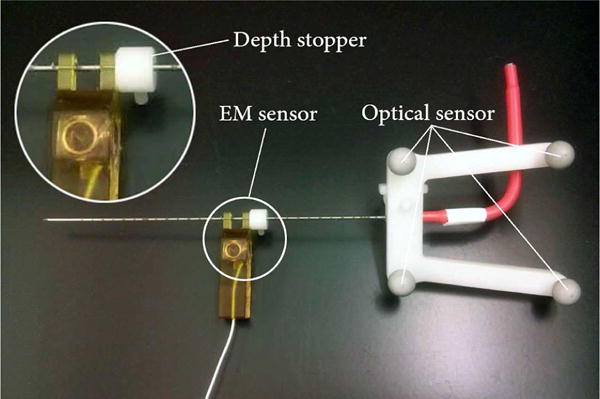
Cryoablation needle mounted with optical and EM sensor. The EM sensor is located 10cm from the needle’s tip using a depth stopper (white)
Fig. 7.
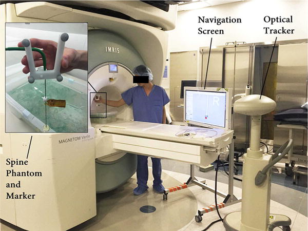
The static tip bending experimental setup at the MRI tunnel entrance
Kalman filter formulation
In many insertion procedures, including cryoablation, the insertion speed is slow enough to be considered as a constant with acceleration variations [15,26], which is often referred to as continuous white noise acceleration model [27,28]. Therefore, the state vector is set as xk = [Ptip(k), Ṗtip(k)]T, and the process model can be formulated in the form of xk = Axk−1 + wk−1 as follows:
| (1) |
where Ts, I3, 03 represent the time step, third-order identity matrix and third-order null matrix, and Ptip(k), Ṗtip(k), denote the tip position, velocity and acceleration, respectively. As we consider the insertion speed as constant, the acceleration element is taken as the process noise, denoted by , where is the process noise covariance matrix.
Four sets of data are obtained in real time during needle insertion—optical sensor-measured needle base position POpt, needle axis orientation estimated by the optical sensor OOpt, EM sensor position PEM and the needle axis orientation estimated by the EM sensor OEM. Using these data, the needle tip position can be estimated in multiple ways, as shown in Table 1.
Table 1.
Different ways to estimate tip position using given setup
| Notation | POpt | OOpt | PEM | OEM | Method |
|---|---|---|---|---|---|
| TIPOpt | ✓ | ✓ | × | × | Assuming straight |
| TIPEM | × | × | ✓ | ✓ | Assuming straight |
| TIPOptEM | ✓ | × | ✓ | × | Assuming straight |
| TIPEMOptOpt | ✓ | ✓ | ✓ | × | Using bending model |
| TIPOptEMEM | ✓ | × | ✓ | ✓ | Using bending model |
For now the bending model can be formulated as in (2) and (3), respectively:
| (2) |
| (3) |
TIPEMOptOpt and TIPOptEMEM can provide better needle tip estimation in a significant bending situation, but relies heavily on the accurate registration of the optical sensor to the EM sensor, making them less accurate in small bending situation than TIPEM. Therefore, for zk = Hxk + vk, an appropriate vector zk should take care of both situation and thus comprise TIPEM, TIPEMOptOpt and TIPOptEMEM, which can be expressed as zk = [g1 (PEM, POpt, OOpt), g2 (POpt, PEM, OEM), TIPEM]T. This fusion scheme is illustrated in Fig. 2. Besides, H is defined as in (4):
| (4) |
The measurement noise is referred to as , where is the measurement noise covariance matrix.
Fig. 2.
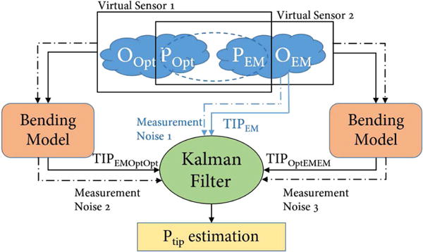
The Kalman fusion process, with 3 measurement inputs, constitutes measurement vector in the Kalman filter
Identification of noise covariance matrix and is a combination of empirical estimation and experimental quantification. We first assumed the covariance matrices only have values on their diagonal entries and estimate the process noise empirically. Then we held the needle in still, record the data from EM and optical sensor, assign variables representing the scaling factors between the process noise and measurement noise. In the end, we implemented Nelder-Mead method on the collected sensor data and identified the scaling variables that minimize the standard deviation of tip estimations [29].
This approach views each estimation method as a virtual sensor. Therefore, it provides a deeper coupling between sensors and a new way to estimate needle tip via multiple sensors. To roughly compare the effectiveness of this sensor fusion scheme with the method proposed in reference [15], we have conducted a simulation experiment assuming the bending models can perfectly represent the actual needle deflection. The sensor noise used in the simulation is obtained from the nominal noise variance of the sensors used in both methods. Statistical analysis shows no statistically significant difference between the two methods (with p value 0.4643). Therefore, while maintaining the effectiveness of estimation, the proposed sensor fusion approach provides a new way of needle deflection estimation feasible in more situations.
Two bending model options
In order to estimate the flexible needle deflection from the kinematic measurements, an efficient and robust bending model is needed. Many different models have been proposed and reviewed in [1,11,15,18]. In our work we assume the deflection is caused by orthogonal force acting on the needle tip and accordingly a planar bending. This assumption allows us to perform model-based sensor fusion with the two sensor inputs. Under this assumption, angular springs formulation is reported to outperform mechanics-based model [18]. The quadratic kinematic bending model was tested in real tissue insertion experiment with good results [15,19]. Therefore, these two models are chosen for our investigation.
Angular springs model
In this method, the needle is modeled as n rigid rods connected by angular springs with the same spring constant k. When an orthogonal force is applied on the needle tip, the needle will deflect causing the springs to extend. The insertion process is slow in real cases, so it can be considered as quasi-static. Therefore, the rods and springs are in equilibrium at each time step. Additionally, in the elastic range of deformations, each spring behaves linearly, i.e., τi = k · qi, where τi is the spring torque at each connecting joint and qi is the relative rod segment deflection angle with reference to the previous rod segment. The angular springs model with the simplification to 5 rigid rods is shown in Fig. 3, and the mechanical relation between each of the rigid rods is expressed in (5).
| (5) |
where Ftip stands for the orthogonal force acting on the needle’s tip and l stands for the length of each segment rod. Equations (5) can be written in the form of k · Φ = Ftip · J(Φ), where Φ = [q1, q2,…, qn]T, and J is the Jacobian function calculating the force-deflection relationship vector. Besides, the magnitude of deflection can be computed from sensor measurements through either of the following equations:
| (6) |
| (7) |
where dEM represents the deviation of the EM sensor from the optical sensor-measured needle orientation and dbase stands for the relative deviation of the needle base from the EM sensor-measured needle orientation, which are both illustrated in Fig. 3.
Fig. 3.
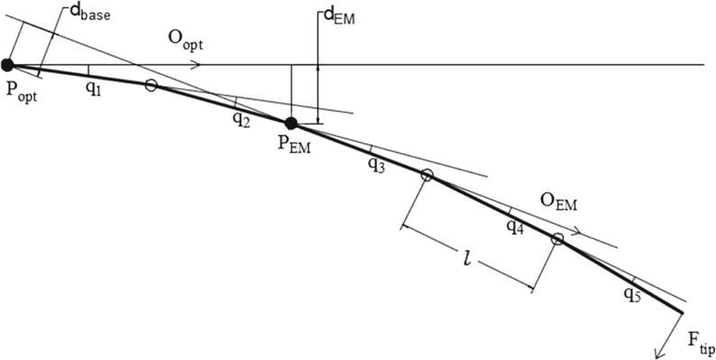
Angular springs model, using 5 rigid rods model for an example
Now we can use the set of Eqs. (5) (6) and (5) (7) to compute the tip estimation TIPEMOptOpt and TIPOptEMEM, respectively. The real system can be large when we model the needle into 26 rods. However, as proposed in [18], the nonlinear system of (5) can be solved efficiently using Picard’s method, which is expressed in (8). Given the needle configuration Φt in prior step, we can use the function J to estimate the needle posture at the next iteration.
| (8) |
However, a known tip force is required for the implementation of this Picard’s method. To identify the relationship between Ftip and dEM or dbase, simulation experiments are conducted and the results are shown in Fig. 4. This result is built upon a known angular springs constant, which is identified through force-deflection calibration experiment. The estimated spring constant is k = 6.37 × 10⁶ (N · mm/rad) for a 26-rod model. The seemingly linearity is the result of large spring constant. In order to realistically model the force–deflection function, a cubic polynomial is fitted with the recorded force–deviation data using the least squares method.
Fig. 4.
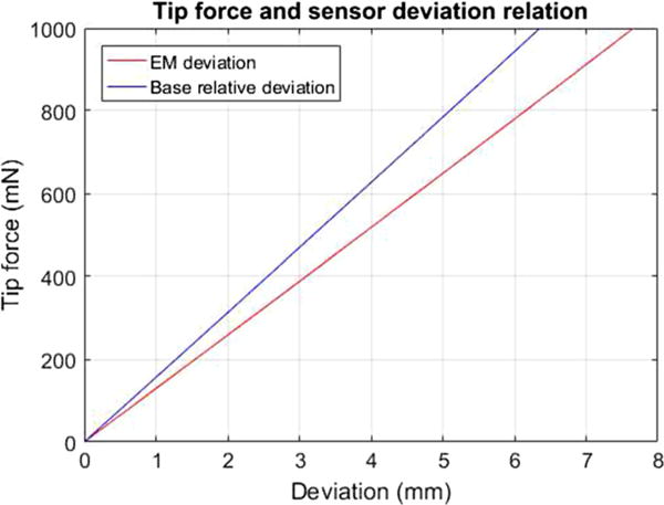
Tip force and deflection relation: Tip force is increasing from 0 to 1000 mN with 50-mN intervals
Collectively, to estimate the tip using this model, the optimal cubic polynomial is used first to estimate Ftip from the measured dEM and dbase, and then the needle configuration equations are solved iteratively using (8).
Quadratic polynomial model
A kinematic quadratic polynomial model was used to estimate the needle deflection in [15,19,30]. This model is described as in (9):
| (9) |
where a is a model parameter and k, which is different from angular spring model’s spring constant k, is a constant estimated through needle bending experiment in “Bending model validation” section.
To compute TIPEMOptOpt, the parameter a can be first obtained by solving the model equation , where x0 and y0 stand for the EM sensor position in the needle base coordinate XOY as shown in Fig. 5. Then by needle length integration, the tip position can be found in XOY coordinate.
Fig. 5.
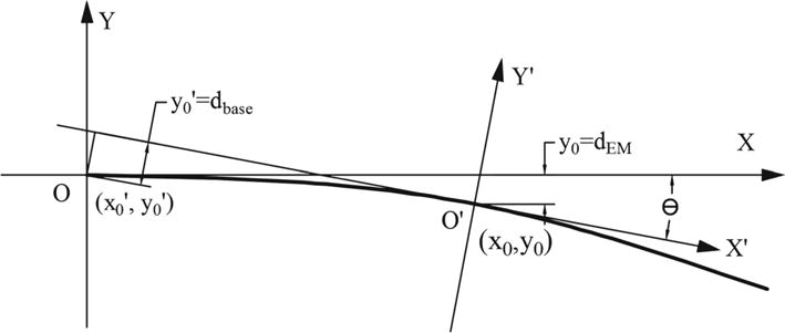
Quadratic polynomial model implementation and coordinates setup
To compute TIPOptEMEM, we also need to identify the coordinate transformation between XOY and X′O′Y′ in Fig. 5. Assuming the needle base is at the point (x0′, y0′) in coordinate X′O′Y′ (EM defined coordinates) and the EM sensor is at the point (x0, y0) in coordinate XOY (needle base optical coordinates), the included angle between XOY and X′O′Y′ is θ. Therefore, the following equations can be set up using the coordinate transformation matrix and kinematic relations:
| (10) |
| (11) |
| (12) |
Given the input value of x0′, y0′, that can be obtained from POpt, PEM, OEM, Eqs. (10), (11), (12) can be solved using trust-region-dogleg algorithm [31]. The output of this method is the model parameter a and EM position in XOY coordinate (x0, y0). The needle tip position in XOY coordinate can be obtained using needle length integration.
Experiments
Bending model validation
In order to initially validate the feasibility of our models, bending experiment was set up to obtain the gold standard needle bending profiles. The needle was coated with ink and was clamped at the base. First we printed the straight needle profile and then bent the needle by pressing the tip orthogonally. With the needle bent and held in position, the bending profile was recorded by pressing the needle on the scale paper. In the end we digitalized the bending profiles by picking discrete points and obtained a cubic polynomial curve as gold standard via least squares regression.
From each gold standard profile, we can obtain corresponding PEM, POpt, OOpt values. Using these values, model parameters can be computed and model predicted curve can be drawn. The results are shown in Fig. 6. The largest tip error is 2.42 and 1.16 mm for angular springs model and quadratic polynomial model, respectively.
Fig. 6.
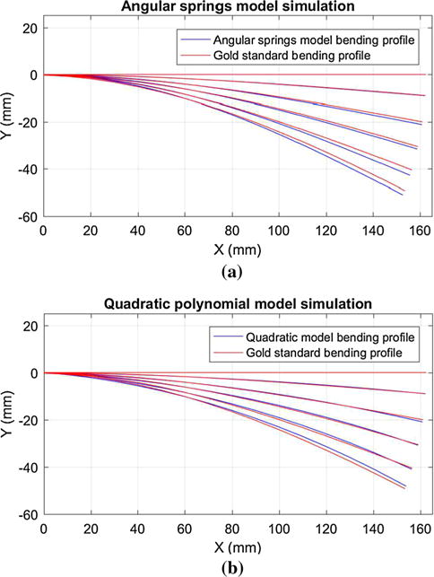
Model validation with gold standard bending profile
It is worth noting that for the quadratic polynomial model, the constant k must first be identified. Through least squares regression, the optimal coefficients for the model y = ax2 + bx are obtained to fit the discrete gold standard bending profile points. For the 5 gold standard bending profiles, the value of b/a remains almost stable, with a mean value of 51.32 and a range from 44.87 to 58.92. Therefore, we set k = 51.32 (1/mm).
Static tip estimation with needle bending
To evaluate the overall performance of our method, we designed the static tip bending experiment, which was conducted in two steps: First, the needle tip was placed at a fixed point, with optical and EM sensor recording for 10 s; second, the needles tip remained at the fixed point and needle was bent by maneuvering the needle base. Similarly, for this dynamic process, sensor measurements were collected for 20 s.
The needle tip position can be estimated from the data collected in the first step. Because EM sensor was closer to the tip and less variation (0.23 mm) was observed, we chose to use PEM and OEM to compute the average tip position as gold standard TIPgold. With the data collected in the second step, we can evaluate the performance of each estimation method. The experimental setup and illustrative result are shown in Figs. 7 and 8, respectively.
Fig. 8.
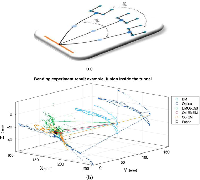
Single experimental result: Each scattered point stands for a single time step record. The left-side points are the estimated tip position using different methods, and the right-side points represent the raw EM or optical measurements. The black sphere is centered at the gold standard point and encompasses 90% of the fusion result points (black points). The lines in the figure illustrate the correlation between different methods at a single time step. They link the estimated tip position to the measured EM or needle base (optical) locations. a Diagram representation of needle bending experiment. b Numerical representation of needle bending experiment
To further evaluate our method, we conducted extensive experiments with different setups: at MRI isocenter or MRI entrance; small bending or large bending; x–y plane bending or x–z plane bending.
MRI isocenter versus MRI entrance While the needle insertion procedure is generally done at the MRI entrance due to the ergonomics, the accuracy of EM sensor is higher at the isocenter. Therefore, isocenter experiments are also conducted to help us better evaluate our method. At either entrance or isocenter, gold standard positions are also changed frequently to avoid local bias.
Small bending versus large bending Our initial insertion experiments in a homogeneous spine phantom using the cone-tip cryoablation needle demonstrated a needle bending of over 10mm. Accordingly, in the second step of this experiment, we attempt to simulate a larger bending that can be anticipated when the needle is inserted through heterogeneous tissue composition, which is a tip deviation of about 40 mm. However, an extra set of static tip estimation experiments was conducted with a relatively small needle deflection of less than 20mm to further validate our approach.
x–y plane bending versus x–z plane bending versus random bending. EM sensor accuracy is often anisotropic, which is also true for our sensor. During experiments, we bent the needle in three patterns: in the x–y plane of the MRI, in the y–z plane and in all directions.
Results analysis
First we look at the result within a single experiment, as shown in Fig. 8. TIPOpt is the most dispersed due to the lack of deflection compensation. If the estimation depends solely on EM sensor, i.e., TIPEM, it will result in a much better estimation since the EM sensor is placed closer to the needle tip and the section from the EM sensor to the needle tip has less bending as models suggested. The TIPOptEMEM (red) demonstrates the best needle tip estimation among non-fusion method, whereas the TIPEMOptOpt approach fails to give a consistent estimation because small errors in OOpt measurement will have large effects on TIPEMOptOpt. The optical-MR registration error and the nonorthogonal tip force introduced by the needle base maneuvering exacerbate the situation. However, better fusion result is observed using TIPEMOptOpt as a fusion element. This can be explained using the directional lines in Fig. 8. The green line that represents the TIPEMOptOpt approach at a particular time step deflects to the left side of the gold point (center of the black sphere), whereas the other four (TIPOptEMEM, TIPOptEM, TIPEM and TIPOpt) deflect to the right side. This relationship holds true for most time steps. Due to the opposite direction of the error vectors TIPEMOptOpt – TIPgold and TIPEM – TIPgold, the fused estimation will be closer to the gold point. Though TIPOptEM can provide certain amount of deflection compensation and exhibit smaller mean estimation error than TIPEMOptOpt, it does not preserve such directional property as TIPEMOptOpt. As a result, it is not included in our fusion approach.
Now we look at the performance variations across different experimental setups as shown in Fig. 9. At both the MRI isocenter and tunnel entrance (650-mm offset from isocenter), we have conducted 15 sets of static tip bending experiment for large bending validation and 15 sets for small bending validation. Within each 15 sets, 5 sets of the needle were bent in the x–y plane of the MRI, 5 sets in y–z plane and 5 sets with motion in all directions.
Fig. 9.
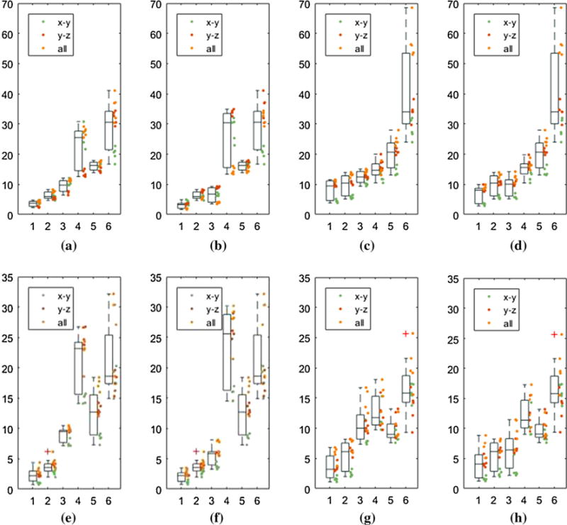
Bending experimental result: For x-axis, numbers from 1 to 6 stand for TIPfused, TIPEM, TIPOptEMEM, TIPEMOptOpt, TIPOptEM, TIPOpt, respectively. Y-axis is the distance (mm) from the estimated tip position to the gold standard tip position. Each bending experiment is represented by a colored dot, which follows three bending patterns, i.e., in the x–y plane, y–z plane and all directions. The mean error improvement is comparing the fused estimation with TIPOpt and TIPEM. a Large-iso-quad: Opt error: 29.23 mm, Fusion error: 3.64 mm, EM error: 6.29 mm. b Large-iso-angular: Opt error: 29.23 mm, Fusion error: 3.15 mm, EM error: 6.29 mm. c Large-entrance-quad: Opt error: 39.96 mm, Fusion error: 8.42 mm, EM error: 9.77 mm. d Large-entrance-angular: Opt error 39.96 mm, Fusion error: 6.90 mm, EM error: 9.77 mm. e Small-iso-quad: Opt error: 21.00 mm, Fusion error: 2.24 mm, EM error: 3.70 mm. f Small-iso-angular: Opt error: 21.00 mm, Fusion error: 2.20 mm, EM error: 3.70 mm. g Small-entrance-quad: Opt error: 16.54 mm, Fusion error: 3.62 mm, EM error: 5.41 mm. h Small-entrance-angular: Opt error: 16.54 mm, Fusion error: 4.20 mm, EM error: 5.41 mm
In general, the estimation error is larger at the 650-mm offset than at the isocenter, which is probably due to the large noise and nonlinearity of the magnetic gradient field around the site. For large bending situation, the estimation accuracy improves from 39.96 mm of the optical sensor-based approach to 6.90 mm of the fusion-based approach using angular springs model (angular) and from 39.96 to 8.42 mm using quadratic polynomial model (quad). Although the reduced error is still large, it should be noted that the large magnitude of the tracking error is due to the significant bending introduced by the needle base maneuvering. For small bending situation, which will take place more often, the error at the MRI entrance is reduced from 16.54 to 4.20 and to 3.62 mm using angular and quad model, respectively. We compare TIPfused to TIPOpt mainly because optical tracking is current standard in OR setting.
We can also observe the variation of the EM sensor accuracy with respect to the bending orientation. As shown in Fig. 9, the green dots, which stand for bending in x–y plane, exhibit much higher accuracy of the EM sensor, thus resulting in a better fusion result. For large bending in x–y plane at the entrance, the tracking error reduces from 28.22 to 3.40 mm and 4.45 mm using angular and quad model, respectively, while the TIPEM error is 5.76 mm at the same time. This result indicates that by maneuvering the needle in the x–y plane, the accuracy of needle placement can be significantly improved.
The comparison of two bending models is made in two parts: accuracy and efficiency. For accuracy, the result shows that the angular springs model can do better than the quadratic polynomial model, but the difference is not large. However, for efficiency, the angular model is far better than the quad model. For a data set of 704 time steps, the cost of angular springs model post-processing is 1.339 s, while the cost for quad model is 30.651 s. It is caused by using the trust-region algorithm to solve the analytical model equations.
Discussion and conclusion
In this paper, we have proposed a model-based multi-sensor fusion scheme to estimate the flexible needle deflection and we studied the feasibility of two needle bending models. In static tip bending experiment, compared to the optical sensor-based navigation approach, which is the current OR standard and generally more reliable in surgical navigation [32], the data fusion method largely reduced the tip estimation error under all circumstances. Besides, comparing to other methods, the approach in this work demonstrates three major advantages: robustness, device compatibility and MRI compatibility.
The bending experiments were done in very different scenarios with purely free-hand manipulation, where significant noise changes will occur. Despite using the same noise matrix, due to Kalman filter’s great capability in capturing the stochastic nature of insertion process, the estimation results tend to show consistent performance. Similar observation is also reported in [15]. This is one advantage of stochastic modeling over other methods relying on exact modeling of needle bending. Besides, the bending model used is also robust to less accurate calibration. For the angular springs model, within the same degree of magnitude of k, parameter changes will lead to needle tip deflection changes less than 0.5 mm.
Our approach does not need instrumentation inside needle lumen, such as FBG sensor or small EM sensor, which is not feasible for functional needles used in procedures like cryoablation. Furthermore, it is also suitable when nonbevel tip needles are involved. Notice that nonbevel tip needles are not “expected” to bend, but bending occurs nonetheless during free-hand operation. Our method shows a “backwards compatibility” as shown by experimental results: When no bending or small bending occurs, the estimation error using our method will be greatly reduced, thus asymptotically approaching current standard tracking scheme without fusion. Free from robotic close-loop actuation also makes our approach feasible in free-hand operation.
One important point of this study is our investigation of an MR-gradient field-driven EM sensor-based implementation. The results demonstrated the possibility to integrate an EM sensor into image-guided surgery with intraoperative MRI. Although replacing the EM sensor with another optical sensor may also allow the needle deflection estimation using our approach, but this EM sensor is crucial in our overall setup because we rely on the EM sensor to complete the final insertion inside the MRI bore when optical tracker fails due to line-of-sight issue [9].
A strong assumption of tip force-initiated needle bending is adopted during the development of this method; however, it should be justifiable especially in our application scenario. First, for cryoablation in the spine region, the insertion depth is shallow compared to the full length of the needle, which means only a small of the needle is interacted with the tissue that the force can be roughly modeled as a point force. Second, the needle used is semi-rigid that the bending profile of which is much more predictable than other soft needles. Third, we do not rely on the needle deflection estimation ability to send the needle to the target. Instead, we rely on the image guidance of a needle which is expected to be straight. Therefore, given that the needle tip force assumption is a stable assumption when no or small bending happens, it can improve the overall image-guided procedure.
This study is served as a pioneer investigation to this new kind of model-based sensor fusion. The static tip bending experiment has demonstrated that given correct bending model, the estimation result will be promising. The complexity of bending model is limited by the availability of measurement inputs; therefore, more sensors involved will enable us to do more realistic model-based estimation, which is one of our future work. Besides, we will attempt to use the new registration method, i.e., using the sensor measurements to do direct registration, instead of the current phantom marker approach which uses traditional least square registration method, to improve the alignment of the EM and the optical sensor. Since our primary objective is to develop a navigation system aimed at providing real-time guidance for accurate needle placement, this work lays the basis for tracking the flexible needle in the presence of significant needle deflection. As part of our future work, we will integrate the data fusion algorithm with our 3D Slicer-based navigation system [33].
Acknowledgments
This work was supported by the National Center for Research Resources and the National Institute of Biomedical Imaging and Bioengineering of the National Institutes of Health through Grant Nos. P41EB015898 and P41RR019703 and Chinese Scholar Council, the National Natural Science Foundation of China under Grants (No. 81201150 and 81171304). This work was also partly supported by the General Financial Grant from the China Post-doctoral Science Foundation (No. 2012M520741) and Specialized Research Fund for the Doctoral Program of Higher Education (No. 20122302120077), Fundamental Research Funds for the Central Universities (No. HIT.NSRIF. 2013106) and Self-Planned Task (No. SKLRS201407B) of State Key Laboratory of Robotics and System (HIT) and International S&T Cooperation Program of China, 2014DFA32890.
Footnotes
Compliance with ethical standards
Conflict of interest: The authors declare that they have no conflict of interest.
References
- 1.Rossa C, Tavakoli M. Issues in closed-loop needle steering. Control Eng Pract. 2017;62:55–69. [Google Scholar]
- 2.Abolhassani N, Patel R, Moallem M. Needle insertion into soft tissue: a survey. Med Eng Phys. 2007;29(4):413–431. doi: 10.1016/j.medengphy.2006.07.003. [DOI] [PubMed] [Google Scholar]
- 3.Dupuy DE, Zagoria RJ, Akerley W, Mayo-Smith WW, Kavanagh PV, Safran H. Percutaneous radiofrequency ablation of malignancies in the lung. Am J Roentgenol. 2000;174(1):57–59. doi: 10.2214/ajr.174.1.1740057. [DOI] [PubMed] [Google Scholar]
- 4.Park YL, Elayaperumal S, Daniel B, Ryu SC, Shin M, Savall J, Black RJ, Moslehi B, Cutkosky MR. Real-time estimation of 3-D needle shape and deflection for MRI-guided interventions. IEEE/ASME Trans Mechatron. 2010;15(6):906–915. doi: 10.1109/TMECH.2010.2080360. [DOI] [PMC free article] [PubMed] [Google Scholar]
- 5.Bartynski WS, Grahovac SZ, Rothfus WE. Incorrect needle position during lumbar epidural steroid administration: inaccuracy of loss of air pressure resistance and requirement of fluoroscopy and epidurography during needle insertion. Am J Neuroradiol. 2005;26(3):502–505. [PMC free article] [PubMed] [Google Scholar]
- 6.Mala T, Edwin B, Mathisen Ø, Tillung T, Fosse E, Bergan A, SØreide O, Gladhaug I. Cryoablation of colorectal liver metastases: minimally invasive tumour control. Scand J Gastroenterol. 2004;39(6):571–578. doi: 10.1080/00365520410000510. [DOI] [PubMed] [Google Scholar]
- 7.Charboneau JW, Reading CC, Welch TJ. Ct and sonographically guided needle biopsy: current techniques and new innovations. AJR Am J Roentgenol. 1990;154(1):1–10. doi: 10.2214/ajr.154.1.2104689. [DOI] [PubMed] [Google Scholar]
- 8.Tesei M, Saccomandi P, Massaroni C, Quarta R, Carassiti M, Schena E, Setola R. IEEE 38th annual international conference of the engineering in medicine and biology society (EMBC) IEEE; 2016. A cost-effective, non-invasive system for pressure monitoring during epidural needle insertion: Design, development and bench tests; pp. 194–197. [DOI] [PubMed] [Google Scholar]
- 9.Gao W, Jiang B, Kacher DF, Fetics B, Nevo E, Lee TC, Jayender J. Real-time probe tracking using EM-optical sensor for MRI-guided cryoablation. Int J Med Rob. 2017 doi: 10.1002/rcs.1871. https://doi.org/10.1002/rcs.1871. [DOI] [PMC free article] [PubMed]
- 10.Dorileo E, Zemiti N, Poignet P. International conference on advanced robotics (ICAR) IEEE; 2015. Needle deflection prediction using adaptive slope model; pp. 60–65. [Google Scholar]
- 11.Roesthuis RJ, Van Veen YR, Jahya A, Misra S. IEEE/RSJ international conference on intelligent robots and systems (IROS) IEEE; 2011. Mechanics of needle-tissue interaction; pp. 2557–2563. [Google Scholar]
- 12.Asadian A, Kermani MR, Patel RV. IEEE/RSJ international conference on intelligent robots and systems (IROS) IEEE; 2011. An analytical model for deflection of flexible needles during needle insertion; pp. 2551–2556. [Google Scholar]
- 13.Park W, Reed KB, Okamura AM, Chirikjian GS. IEEE International conference on robotics and automation (ICRA), 2010. IEEE; 2010. Estimation of model parameters for steerable needles; pp. 3703–3708. [DOI] [PMC free article] [PubMed] [Google Scholar]
- 14.Taffoni F, Formica D, Saccomandi P, Pino GD, Schena E. Optical fiber-based MR-compatible sensors for medical applications: an overview. Sensors. 2013;13(10):14105–14120. doi: 10.3390/s131014105. [DOI] [PMC free article] [PubMed] [Google Scholar]
- 15.Sadjadi H, Hashtrudi-Zaad K, Fichtinger G. Fusion of electromagnetic trackers to improve needle deflection estimation: simulation study. IEEE Trans Biomed Eng. 2013;60(10):2706–2715. doi: 10.1109/TBME.2013.2262658. [DOI] [PubMed] [Google Scholar]
- 16.Jiang B, Gao W, Kacher DF, Lee TC, Jayender J. International conference on medical image computing and computer-assisted intervention. Springer; 2016. Kalman filter based data fusion for needle deflection estimation using optical-em sensor; pp. 457–464. [Google Scholar]
- 17.Roth A, Nevo E. Method and apparatus to estimate location and orientation of objects during magnetic resonance imaging. 9,037,213 US Patent. 2015
- 18.Goksel O, Dehghan E, Salcudean SE. Modeling and simulation of flexible needles. Med Eng Phys. 2009;31(9):1069–1078. doi: 10.1016/j.medengphy.2009.07.007. [DOI] [PubMed] [Google Scholar]
- 19.Wan G, Wei Z, Gardi L, Downey DB, Fenster A. Brachytherapy needle deflection evaluation and correction. Med Phys. 2005;32(4):902–909. doi: 10.1118/1.1871372. [DOI] [PubMed] [Google Scholar]
- 20.Chui CK, Chen G. Kalman filtering: with real-time applications. Springer; Berlin: 2008. [Google Scholar]
- 21.Hall DL, Llinas J. An introduction to multisensor data fusion. Proc IEEE. 1997;85(1):6–23. [Google Scholar]
- 22.Yan KG, Podder T, Xiao D, Yu Y, Liu TI, Ling KV, Ng WS. Medical image computing and computer-assisted intervention–MICCAI 2006. Springer; 2006. Online parameter estimation for surgical needle steering model; pp. 321–329. [DOI] [PubMed] [Google Scholar]
- 23.www.symbowmed.com. Accessed 14 Mar 2016
- 24.Nevo E. Method and apparatus to estimate location and orientation of objects during magnetic resonance imaging. 6,516,213 US Patent. 2003
- 25.Yaniv Z. Which pivot calibration? SPIE medical imaging, international society for optics and photonics. 2015:941527–941527. [Google Scholar]
- 26.Crouch JR, Schneider CM, Wainer J, Okamura AM. Medical image computing and computer-assisted intervention–Miccai 2005. Springer; 2005. A velocity-dependent model for needle insertion in soft tissue; pp. 624–632. [DOI] [PubMed] [Google Scholar]
- 27.Bar-Shalom Y, Li XR, Kirubarajan T. Estimation with applications to tracking and navigation: theory algorithms and software. Wiley; Hoboken: 2004. [Google Scholar]
- 28.Cerveri P, Pedotti A, Ferrigno G. Robust recovery of human motion from video using kalman filters and virtual humans. Hum Mov Sci. 2003;22(3):377–404. doi: 10.1016/s0167-9457(03)00004-6. [DOI] [PubMed] [Google Scholar]
- 29.Lagarias JC, Reeds JA, Wright MH, Wright PE. Convergence properties of the nelder-mead simplex method in low dimensions. SIAM J Optim. 1998;9(1):112–147. [Google Scholar]
- 30.Khadem M, Rossa C, Sloboda RS, Usmani N, Tavakoli M. Ultrasound-guided model predictive control of needle steering in biological tissue. J Med Robot Res. 2016;1(01):1640007. [Google Scholar]
- 31.Coleman TF, Li Y. An interior trust region approach for nonlinear minimization subject to bounds. SIAM J Optim. 1996;6(2):418–445. [Google Scholar]
- 32.Birkfellner W, Watzinger F, Wanschitz F, Ewers R, Bergmann H. Calibration of tracking systems in a surgical environment. IEEE Trans Med Imaging. 1998;17(5):737–742. doi: 10.1109/42.736028. [DOI] [PubMed] [Google Scholar]
- 33.Jayender J, Lee TC, Ruan DT. Real-time localization of parathyroid adenoma during parathyroidectomy. N Engl J Med. 2015;373(1):96–98. doi: 10.1056/NEJMc1415448. [DOI] [PMC free article] [PubMed] [Google Scholar]


