Abstract
This paper studies the fabrication and testing of a magnet free piezoelectric energy harvester (EH) for powering biomedical devices and sensors inside the body. The design for the EH is a fan-folded structure consisting of bimorph piezoelectric beams folding on top of each other. An actual size experimental prototype is fabricated to verify the developed analytical models. The model is verified by matching the analytical results of the tip acceleration frequency response functions (FRF) and voltage FRF with the experimental results. The generated electricity is measured when the EH is excited by the heartbeat. A closed loop shaker system is utilized to reproduce the heartbeat vibrations. Achieving low fundamental natural frequency is a key factor to generate sufficient energy for pacemakers using heartbeat vibrations. It is shown that the natural frequency of the small-scale device is less than 20 Hz due to its unique fan-folded design. The experimental results show that the small-scale EH generates sufficient power for state of the art pacemakers. The 1 cm3 EH with18.4 gr tip mass generates more than16 μW of power from a normal heartbeat waveform. The robustness of the device to the heart rate is also studied by measuring the relation between the power output and the heart rate.
Keywords: piezoelectric energy harvester, pacemaker energy harvester, fan-folded structure, power generation from heartbeat, experimental vibration, frequency response function
1. Introduction
During the past decades, the number of people receiving cardiac pacemaker has been increasing in the US [1]. In the traditional pacemakers, the patient needs to do a surgery every 7–12 years to have the old pacemaker removed due to the battery depletion and receive a new pacemaker [2, 3]. The surgery is costly and has its own risks. The size of the pacemakers has been reduced significantly by introducing the leadless pacemakers. Leadless pacemakers are much smaller than the conventional pacemakers and they are attached to the inner wall of the heart. Initially, the working lifetime of leadless pacemakers was envisioned for 25 years; however, their development was unsuccessful due to challenges in reducing the size of their batteries [4].
In leadless pacemakers, the same battery issue exists. However, unlike the traditional pacemakers, the old pacemaker is not removed. The old leadless pacemaker is left in the heart and a new leadless pacemaker is implanted next to the old one. The battery life in leadless pacemakers varies between 7 and 12 years depending on the usage and other factors [2, 3]. The procedure of placing a leadless pacemaker in the heart does not involve a complicated surgery. However, this procedure is still costly and the heart space gets filled up with the old not-working pacemakers. This issue harms the young patients who might need several pacemakers during their lifetime. The mentioned issues with the battery of the pacemakers show the demand for developing a lifetime energy source, to be used in the pacemakers instead of the current batteries.
Several research groups have looked into energy harvesting for pacemakers from lung motion [5], heartbeat motion and vibration [6–10], and blood pressure [11]. Piezoelectric micro energy harvesters have shown promising results in generating electricity for pacemakers from heartbeat vibrations [8, 11–13]. Some groups have looked at other ways such as acoustic power transfer [14], magnetic energy harvesters [15], and kinetic and thermal energy harvesters [16] for generating electricity for biomedical devices. Due to some restrictions, none of these energy harvesters have been implanted inside any commercial pacemakers. The restrictions include but not limited to the size of the EH, not producing sufficient power, stitching the EH to the heart tissue, unreliability, fabrication difficulties, magnetic resonance imaging (MRI) incompatibility.
Different techniques have been utilized by several research groups for decreasing the natural frequency of a small size structure. Fan-folded configuration [17–21], elephant [22] and zig-zag [23] structures allow getting low natural frequency in small size devices. However, none of the previous studies has looked into building an MRI compatible energy harvester for leadless pacemakers.
In this article, our previously proposed magnet free fanfolded EH [18] is fabricated and experimentally tested. The results in this paper confirm our previous theoretical results [18] that a fan-folded design allows adjusting the natural frequency of the energy harvester to match the frequency region where the heartbeat wave has the highest amplitude. Two porotypes are fabricated and experimentally tested and the experimental results are compared with the theoretical results. At the end, the small-size prototype is tested with replicated heartbeat vibrations at different heart rates, showing sufficient energy to power pacemakers from the heartbeat.
2. Prototypes structure
The proposed design for our energy harvester is a fan-folded design. The design consists of two to five piezoelectric beams stacked on top of each other. When the device vibrates, the beams deflect and due to the strain in the beams, the piezoelectric layers produce electricity. The beams are connected to each other using rigid links providing clamp boundary condition. Figure 1 shows a three beam energy harvester with a tip mass. One end of the bottom beam is fixed while one end of the top beam is free to move. In order to reduce the natural frequency of the EH, a tip mass is added to the top beam. Tip mass also increases the force coefficient term, which increases the generated power of the device [18]. Since there are no magnetic materials used in our energy harvester, our device is MRI compatible, which means the patient can do MRI while having our energy harvester inside their body.
Figure 1.
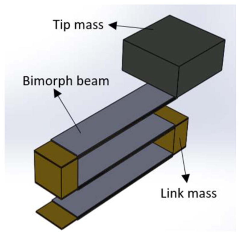
Proposed fan-folded energy harvester with a tip mass.
2.1. Design constraints and objectives
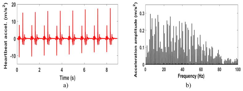
The objective of the proposed EH is to power pacemakers using heartbeat. Figure 2(a) shows a normal heartbeat wave in the time domain measured by Kanai [24]. It is observed that each beat acts as an excitation similar to an impulse. Therefore, the heartbeat waveform contains a wide range of frequencies. Which means that the high amplitude frequencies might not be the same as the frequency of the heart rate (around 1 Hz for a normal heart rate). Figure 2(b) shows the frequency domain of the measured heartbeat. Most of the high amplitude frequencies are less than 50 Hz. In order to generate sufficient power, the first natural frequency of the EH needs to be in the region where the heart wave has the highest amplitude frequencies. A volume size constraint of 1 cm3 is considered for the EH. Keeping the natural frequency lower than 50 Hz for a very small EH, is a major challenge for the final design. Moreover, there are several other criteria to be satisfied for the final design. A safety factor needs to be considered for the beams to assure that the EH does not break due to bending moments even after a high number of excitations. The links need to be high enough to avoid any collision between the beams. The materials used in the prototype need to be magnet free and the most important design factor to be satisfied is generating enough power for implantable biomedical devices inside the body. Pacemakers need less than 10 μW to operate [2, 3, 25]. In practice, a power management circuit needs to be used in the electrical circuitry to provide accurate and steady voltage output for biomedical devices. A backup battery or a super capacitor needs to be incorporated into the pacemaker as well to store the generated energy for when it is needed. Several groups have studied power management circuits (PMC), rectification circuit by using equivalent impedance approach [26–28], and super-capacitors for small energy harvester [29, 30]. Our EH harvester is designed to generate more than 10 μW to compensate for the power loss in available PMCs in the market.
Figure 2.
(a) Normal heartbeat vibrations in the time domain. (b) Fourier transform of a normal heartbeat.
To experimentally verify the theoretical results [18], two prototypes are built; a large prototype and a small one. The larger prototype was studied in [18] and the results are discussed in this paper in more details. It is more convenient to fabricate and test a large prototype than test the actual size 1 cc (cubic centimeter) prototype and that is the main reason the large-scale specimen was built and tested prior to the actual size prototype.
2.2. Prototype 1
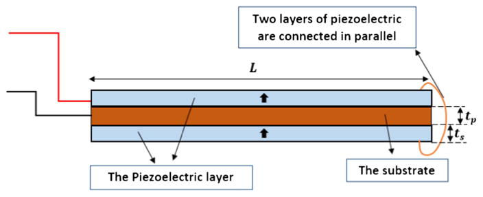
The first prototype is a large-scale prototype made of aluminum to study the principles of fan-folded energy harvesters. The length of the beams are 3.2× the actual size and the number of the beams varies from one up to four. Each beam is 72.0 mm long (L), 6.6 mm wide, and 3.3 mm thick (ts). Only one patch of piezoelectric material is attached to each beam to make unimorph beams. The piezoelectric patches are 67.3 mm long, 6.6 mm wide, and 0.26 mm thick (tp). Figure 3 shows the schematics and the wiring of each beam. Each beam is connected to the other beams using aluminum links and two bolts on each side. Each link with the connecting bolts weighs 1.6 g (0.8 g + 4 × 0.2 g) Using bolts for connecting the beams, makes it possible to add or remove the beams easily. Figure 4 shows a four-beam aluminum configuration. Since the links are made of aluminum, all the substrates of the beams are connected to each other.
Figure 3.
The schematics of a unimorph beam.
Figure 4.
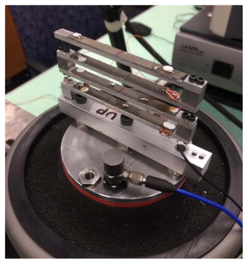
A four-beam large-scale EH mounted on the closed loop shaker.
The polarization of the piezoelectric patches is chosen based on the first mode shape [23] to maximize the output voltage. The piezoelectric patches are connected in parallel configuration electrically. For a four beam structure, there are totally five wires connected to the device. One common wire connected to all the substrates and four wires connected to the piezoelectric patch of each beam. The common wire is connected to one end of the load resistor and the other four wires are connected to the other end of the resistor.
2.3. Prototype 2
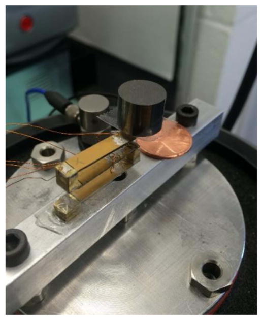
A small-scale magnet free prototype with three bimorph beams is fabricated to comply with available pacemaker size. The presented prototype is the outcome of numerous simulations to find the optimized parameters. Our proposed EH is a three beam fan-folded structure. Each beam consists of a 0.19 mm thick brass substrate and two 0.19 mm thick piezoelectric patches. PSI-5A4E PZT sheets from PIEZO SYSTEMS, INC., are used as the piezoelectric element. Each beam is 20 mm long and 5 mm wide. Links made of brass are used to connect the beams. Each link is 5 mm high. Figure 5 shows the small-scale prototype. None of the materials used in this prototype are magnetics which makes it safe for a person to do MRI while having this EH inside their pacemaker. There is a size constraint for the EH that can be implanted inside the pacemakers. The volume of the EH without the tip mass is restricted to not exceed 1 cm3. On each beam, the polarization of the piezoelectric patches is in the same direction and they are connected in parallel configuration electrically (figure 6). The solid arrows on the piezoelectric patches in figure 6 show the polarity of the patches. Conductive epoxy is used to connect the piezoelectric patches to the substrate and a non-conductive epoxy is used to connect each beam to the brass links and thus each beam is electrically isolated from the other beams. When the substrates of the beams are not connected to each other, there is no charge cancellation between the beams. Two wires are connected to each beam, one from the substrate and one from the piezoelectric patches. In the experimental tests, the power generated from each beam is measured individually. This allows us to experiment with the polarity of the patches and find the wiring connections that gives the maximum power output. In the real device that goes into the pacemaker, the wires from the beams are connected permanently. Thus, the configuration that gives the maximum power is selected as the permanent configuration for connecting the wires. In order to prove that the modeling is scalable and the same governing equations in [18] can be used for this prototype, a series of frequency sweep tests are conducted and the theoretical FRF results are compared to the experimental data. Then the device is tested for energy harvesting from the heartbeat vibrations.
Figure 5.
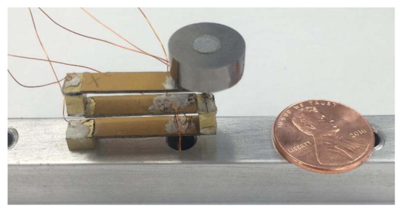
Small-scale brass energy harvester and 9.4 g tungsten tip mass.
Figure 6.
The schematics of a bimorph beam with the parallel electrical connection.
3. Theoretical modeling
The modeling of a fan-folded configuration was studied in [18]. The expression for the multi-mode power frequency response function is [31]:
| (1) |
where p is the output power, ab is the base acceleration, R is the load resistor, Cp is the overall internal capacitance for the piezoelectric layers, ωnj is the natural frequency of the jth mode, ζ is the damping, χj and γj are the coupling coefficient and the base acceleration coefficient. Please refer to the [18] to read more about the details on the governing equations, finding the mode shapes, and why the fan-folded design is chosen as the configuration of the energy harvester. Other methods in the literature, such as the transfer matrix method [19, 32] can be used for solving the governing equations of our fan-folded design too.
4. Experimental characterization
In this section, it is shown that the same governing equations of the large-scale prototype are applicable to the small-size prototype by matching the experimental results and the theoretical results for the small-scale prototype. Then, the small-size prototype is tested with replicated heartbeat vibration and the output power is measured.
4.1. Experimental setup
The prototypes are tested by mounting them on a closed loop shaker and measuring the generated voltage and the tip acceleration once while they get excited by sinusoidal inputs with different frequencies (sine sweep) to find the FRFs and once while the excitation force is the heartbeat waveform. The voltage is measured across a load resistor. The shaker is a Labworks LW140 electromagnetic shaker controlled by a B&K laser vibration closed loop controller. An accelerometer is used to measure the base acceleration and a Polytec laser vibrometer is used to measure the tip velocity and displacement of the top beam.
4.2. Characterization with sine wave
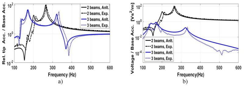
A series of sine sweep tests are performed to compare the theoretical FRF results with the experimental FRF results. Figure 7(a) shows the theoretical results and the experimental results of the relative tip acceleration for the large-scale prototype. One configuration has two beams and the other configuration consists of three beams. Figure 7(b) depicts the voltage FRFs of these two configurations. Please refer to [18] for more results of the large-scale prototype. The large-scale FRF results are used to design and optimize the small-scale prototype.
Figure 7.
Theoretical (solid lines) and experimental (dashed lines) frequency response function (FRF) of the (a) relative tip acceleration and (b) generated voltage to the base acceleration for a two-beam structure (black) and three-beam structure (blue).
The peaks in the FRF plots show the natural frequencies. The first natural frequency of the two-beam large-scale structure is 213 Hz and the first natural frequency of the three-beam large-scale structure is 133.3 Hz. It is observed that the number of beams affects the first natural frequency significantly. Khattak in his paper [17] explains the behavior of the natural frequencies and why there are repeated resonances in a fan-folded structure. One of the challenges for the 1cc (one cubic centimeter) design is to find the optimal number of beams to have a low natural frequency while not exceeding the size limit. As studied in [18], for the one-beam and two-beam configurations of the large-scale prototype, we observe a very good match between the predicted theoretical results and the experimental results. However, as the number of beams increases, we observe some discrepancy between the two results. There are a couple of reasons for that. The main reason is related to the links. In our model, the links are assumed to be completely rigid and provide a perfect clamp boundary condition, however in practice, the links are not completely rigid and they do not provide the ideal clamp condition at the ends. As the number of the beams increase, the moment of inertia of the whole structure gets larger which causes some discrepancy too. As the results show, i.e. our model predicts the amplitude and the frequency of the first natural frequency within a satisfactory range. In our application, most of the energy content of the excitation vibration, heartbeat vibrations, is in the low frequencies (figure 2(b)). Thus, it can be concluded that most of the generated electricity comes from the first natural frequency of the EH. As it is shown in the next section, the discrepancy in the high frequencies does not cause a discrepancy in the generated power from the heartbeat between the model and the experiment.
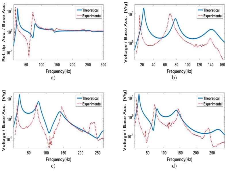
Figure 8 shows the FRF of the small brass prototype with a 9.4 g tip mass shown in figure 5. The tip acceleration of the energy harvester and the voltage of each beam to the base acceleration are plotted in the frequency domain. The voltage is measured across a 40 KΩ resistor. The beam on the bottom is called the first beam, the beam in the middle is the second beam, and the beam on the top is the third beam. Studying the generated voltage of each beam individually, lets us recognize if there is any problem with any of the beams and also helps us with finding the optimized electrical connections for our final design. There is a good match between the two results which means the assumptions for simulating the power output from the heartbeat vibrations in [18] are valid for the small-scale prototype too. The first resonance is 15.79 Hz, which shows that the design significantly reduces the natural frequency of the energy harvester. The natural frequency of the device without the tip mass is around 100 Hz.
Figure 8.
Theoretical (solid line) and experimental (dashed line) frequency response function (FRF) of the (a) relative tip acceleration to the base acceleration for a three beam small-scale prototype with nonconductive connections and 9.4 g tip mass. FRFs of the generated voltage across a 40 KΩ resistor from the (b) first, (c) second, and the (d) third beam.
4.3. Power generated from the heartbeat
In this part, we measure the average power output of the small brass energy harvester with three different tip masses while they are excited by the heartbeat waveform as the input excitation. The energy harvester is mounted on the shaker where an accelerometer measures the base accelerations and feeds it into the controller to ensure that the shaker is following the same excitation as the heartbeat pattern in figure 2(a). The power output is measured by calculating the average power as . The RMS voltage is measured across the load resistor connected to the energy harvester. The optimal electrical connections of the beams are found to match the first mode shape of the device. The piezoelectric patches of the first beam and the top beam are connected by wires to the substrate of the second beam and the piezoelectric patches of the second beam are connected to the substrates of the first and the top beam.
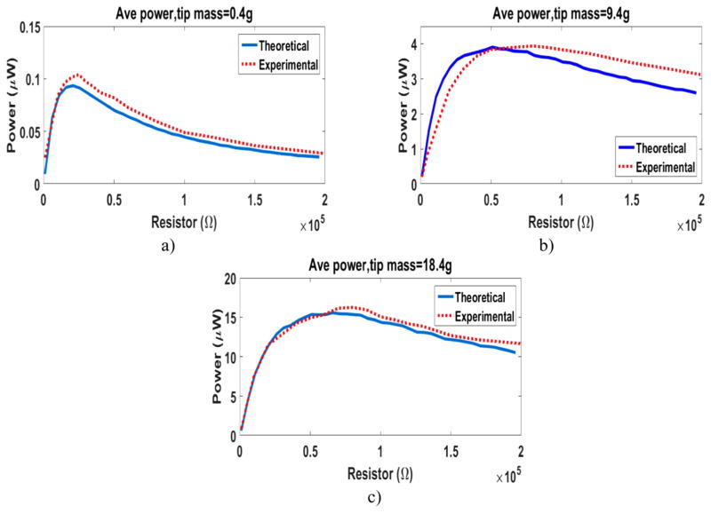
In order to find the maximum power, a resistor sweep test is performed on the energy harvester with three different tip masses. Tungsten is used for the tip mass due to its high density. We use (a) 0.4 g, (b) 9.4 g, and (c) 18.4 g (figure 9) tungsten tip masses. Figure 10 shows the power output generated from these three cases of the small-size prototype. For all the results in figure 10, the bimorph beams are connected in parallel electrically and the configuration of the wires is based on maximizing the power output. There is a good match between the predicted theoretical results using our model and the results from the experiments. The importance of the added tip mass in increasing the generated power is observed. Figure 10 shows as the tip mass increases, the optimum resistor gets larger. The optimum resistors are 25 KΩ, 60 KΩ, and 80 KΩ for the EH with 0.4 g, 9.4 g, and 18.4 g tip mass respectively. The method in [33] is used to predicts the vicinity of the optimal resistor. Based on the definition in [33], the small prototype in figure 9 is categorized under medium electromechanical coupling energy harvesters. The experimental results show that the optimal resistor is in the vicinity of the optimal resistor calculated by:
| (2) |
where is the optimal dimensionless resistor at short circuit resonance, and ke is the dimensionless electromechanical coupling factor. For the prototype in figure 9 with 18.4 g tip mass, is 8.8 and the optimal resistor calculated from equation (2) is 84 KΩ. The maximum accumulative power from all the three beams of the EH with the 18.4 g tip mass is 16.25 μW. Considering the size of the energy harvester, the generated power is satisfactory and can be used to power medical devices inside the body using heartbeat. Pacemakers are a good example of the medical devices that can benefit from this technology.
Figure 9.
Small-scale prototype with nonconductive links and 18.4 g tip mass. Made of brass substrates and bimorph beams.
Figure 10.
Resistor sweep for the generated average power from the small-scale energy harvester using heartbeat vibrations with (a) 0.4 g, (b) 9.4 g, and (c) 18.4 g tungsten tip mass.
The robustness of the device with 18.4 g tip mass to the heartbeats is studied by measuring the power output at different heart rates. The power is calculated across an 80 kΩ resistor. Figure 11 shows the theoretical results from the model and the experimental results of the test. The x-axis shows different heart rates from 7 beats to 350 beats per minute (BMP). For a wide range between 20 beats to 100 beats per minute, the EH generates more than 10 μW which is sufficient for powering a pacemaker. The average generated power for the range of 20–100 BPM is 15.2 μW and the maximum generated power is at 28 beats per minute with more than 20 μW. A backup battery or a super capacitor can be used to store the extra energy when the EH generates more energy than what the pacemaker consumes. This energy can be used when the pacemaker needs more power than what the EH generates. The effect of the heart tissue over the generated power from a piezoelectric energy harvester was studied in [34]. Based on the results in [34], if the EH is placed inside a commercial leadless pacemaker and mounted to the heart inner wall, we do not expect any decrease in the power output due to the heart tissue.
Figure 11.
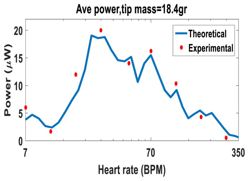
Generated power from the small-scale prototype with an 18.4 g tip mass at different heart rates.
5. Conclusion
This paper studied the experimental investigation of fan-folded piezoelectric energy harvesters for powering implantable biomedical devices from the heartbeat. It was shown that the 1 cm3 piezoelectric energy harvester generates sufficient energy from the heartbeat vibrations to power pacemakers. Two different prototypes were developed and fabricated. The MRI compatible small prototype was designed based on the size constraints of a pacemaker. It was shown that at the normal heart rate, the device generates 16.25 μW with 18.4 g tungsten tip mass, which is sufficient for powering pacemakers. The experimental results of the prototypes were compared to the theoretical results in order to verify the developed analytical model. It was experimentally shown that the power output of the small prototype is robust to the heart rate variation for a wide range of heartbeats. The proposed fan-folded configuration can be used to reduce the high natural frequency of small size devices for energy harvesting applications.
Acknowledgments
The small brass prototypes were fabricated by Johnson Matthey Piezo Products. This research was supported by Clinical and Translational Pilot Studies Program from University at Buffalo.
References
- 1.Greenspon AJ, et al. Trends in permanent pacemaker implantation in the United States from 1993 to 2009: increasing complexity of patients and procedures. J Am Coll Cardiol. 2012;60:1540–5. doi: 10.1016/j.jacc.2012.07.017. [DOI] [PubMed] [Google Scholar]
- 2.Nippoldt D, Whiting J. Micra transcatheter pacing system: FIH announcement. Medtronic Data on File 2014
- 3.Nippoldt D, Whiting J. Micra transcatheter pacing system: device volume characterization comparison. Medtronic Data on File 2014 [Google Scholar]
- 4.Bilitch M. Leadless cardiac pacer. 4,256,115 US Patent. 1981
- 5.Dagdeviren C, et al. Conformal piezoelectric energy harvesting and storage from motions of the heart, lung, and diaphragm. Proc Natl Acad Sci. 2014;111:1927–32. doi: 10.1073/pnas.1317233111. [DOI] [PMC free article] [PubMed] [Google Scholar]
- 6.Goto H, Sugiura T, Harada Y, Kazui T. Feasibility of using the automatic generating system for quartz watches as a leadless pacemaker power source. Med Biol Eng Comput. 1999;37:377–80. doi: 10.1007/BF02513315. [DOI] [PubMed] [Google Scholar]
- 7.Roberts P, Stanley G, Morgan JM. Harvesting the energy of cardiac motion to power a pacemaker. Circulation. 2008;118:679–80. [Google Scholar]
- 8.Karami MA, Inman DJ. Powering pacemakers from heartbeat vibrations using linear and nonlinear energy harvesters. Appl Phys Lett. 2012;100:042901. [Google Scholar]
- 9.Zurbuchen A, et al. Energy harvesting from the beating heart by a mass imbalance oscillation generator. Ann Biomed Eng. 2013;41:131–41. doi: 10.1007/s10439-012-0623-3. [DOI] [PubMed] [Google Scholar]
- 10.Alrashdan MH, Hamzah AA, Majlis B. Design and optimization of cantilever based piezoelectric micro power generator for cardiac pacemaker. Microsyst Technol. 2015;21:1607–17. [Google Scholar]
- 11.Deterre M. PhD Thesis. Université Paris Sud; 2013. Toward an energy harvester for leadless pacemakers. [Google Scholar]
- 12.Hwang GT, et al. Self-powered cardiac pacemaker enabled by flexible single crystalline PMN-PT piezoelectric energy harvester. Adv Mater. 2014;26:4880–7. doi: 10.1002/adma.201400562. [DOI] [PubMed] [Google Scholar]
- 13.Ansari M, Karami MA. Nonlinear thermally buckled piezoelectric energy harvester. ASME 2016 International Design Engineering Technical Conferences and Computers and Information in Engineering Conference; 2016. V006T09A065. [Google Scholar]
- 14.Basaeri H, Christensen DB, Roundy S. A review of acoustic power transfer for bio-medical implants. Smart Mater Struct. 2016;25:123001. [Google Scholar]
- 15.Kim SH, Shin J, Hashi S, Ishiyama K. A novel all-in-one magnetic pump and power harvester design for biomedical applications. Smart Mater Struct. 2011;20:035014. [Google Scholar]
- 16.Cadei A, Dionisi A, Sardini E, Serpelloni M. Kinetic and thermal energy harvesters for implantable medical devices and biomedical autonomous sensors. Meas Sci Technol. 2013;25:012003. [Google Scholar]
- 17.Khattak A, Garvey S, Popov A. Repeated resonances in folded-back beam structures. J Sound Vib. 2006;290:309–20. [Google Scholar]
- 18.Ansari MH, Karami MA. Modeling and experimental verification of a fan-folded vibration energy harvester for leadless pacemakers. J Appl Phys. 2016;119:094506. [Google Scholar]
- 19.Reissman T, Wickenheiser A, Garcia E. Generalized solutions of piezoelectric vibration-based energy harvesting structures using an electromechanical transfer matrix method. J Vib Acoust. 2016;138:041001. [Google Scholar]
- 20.Gong LJ, Pan QS, Li W, Yan GY, Liu YB, Feng ZH. Harvesting vibration energy using two modal vibrations of a folded piezoelectric device. Appl Phys Lett. 2015;107:033904. [Google Scholar]
- 21.Zhou S, Hobeck JD, Cao J, Inman DJ. Analytical and experimental investigation of flexible longitudinal zigzag structures for enhanced multi-directional energy harvesting. Smart Mater Struct. 2017;26:035008. [Google Scholar]
- 22.Sharpes N, Abdelkefi A, Priya S. Two-dimensional concentrated-stress low-frequency piezoelectric vibration energy harvesters. Appl Phys Lett. 2015;107:093901. [Google Scholar]
- 23.Karami MA, Inman DJ. Electromechanical modeling of the low-frequency zigzag micro-energy harvester. J Intell Mater Syst Struct. 2011;22:271–82. [Google Scholar]
- 24.Kanai H, Sato M, Koiwa Y, Chubachi N. Transcutaneous measurement and spectrum analysis of heart wall vibrations. IEEE Trans Ultrason Ferroelectr Freq Control. 1996;43:791–810. [Google Scholar]
- 25.OHM OJ, Danilovic D. Improvements in pacemaker energy consumption and functional capability: four decades of progress. Pacing Clin Electrophysiol. 1997;20:2–9. doi: 10.1111/j.1540-8159.1997.tb04805.x. [DOI] [PubMed] [Google Scholar]
- 26.Lien I, Shu Y. Array of piezoelectric energy harvesting by the equivalent impedance approach. Smart Mater Struct. 2012;21:082001. [Google Scholar]
- 27.Bayik B, Aghakhani A, Basdogan I, Erturk A. Equivalent circuit modeling of a piezo-patch energy harvester on a thin plate with AC–DC conversion. Smart Mater Struct. 2016;25:055015. [Google Scholar]
- 28.Aghakhani A, Basdogan I, Erturk A. Multiple piezo-patch energy harvesters integrated to a thin plate with AC-DC conversion: analytical modeling and numerical validation. Proc SPIE. 2016;9806:98060C. [Google Scholar]
- 29.Boisseau S, Gasnier P, Gallardo M, Despesse G. Self-starting power management circuits for piezoelectric and electret-based electrostatic mechanical energy harvesters. J Phys : Conf Ser. 2013;476:012080. [Google Scholar]
- 30.Kong N. PhD Thesis. Virginia Polytechnic Institute and State University; 2011. Low-power power management circuit design for small scale energy harvesting using piezoelectric cantilevers. [Google Scholar]
- 31.Ansari M, Karami MA. Heartbeat energy harvesting using the fan-folded piezoelectric beam geometry. ASME 2014 Int. Design Engineering Technical Conf. and Computers and Information in Engineering Conf; 2015. DETC2015-47698. [Google Scholar]
- 32.Reissman T, Garcia E. Electro-mechanical effect on resonances in fan-folded piezoelectric beam structures. CanSmart Int. Workshop on Smart Materials and Smart Structures; 2008. pp. 23–4. [Google Scholar]
- 33.Shu Y, Lien I. Analysis of power output for piezoelectric energy harvesting systems. Smart Mater Struct. 2006;15:1499. [Google Scholar]
- 34.Galbier AC, Karami MA. A bistable piezoelectric energy harvester with an elastic magnifier for applications in medical pacemakers. ASME 2016 Conf. on Smart Materials, Adaptive Structures and Intelligent Systems; 2016. V002T07A008. [Google Scholar]


